LIFT INCREASING MEANS
As already noted, a low-drag wing designed for high-speed flight in its flight configuration does not have good load-bearing properties at low flight speeds and therefore has very high stall speeds. A high stall speed in a flight configuration could be allowed subject to the obligatory condition of a thorough analysis of all speed reserves and aircraft operating rules, but such a speed is unacceptable because this increases the takeoff and landing distances of the aircraft. Therefore, to reduce the stall speed and associated speeds during takeoff and landing, devices that help increase lift are used. The use of these devices naturally helps reduce the takeoff and landing distance of the aircraft.
Let us turn once again to the lift force formula c ff S-V 2 pl/ 2 and remember that S is the effective wing area and With at - lift coefficient.
The principle of operation of the flaps located along the trailing edge of the wing is clear. Such flaps, with the exception of simple flaps and split flaps, provide increased lift due to:
A) an increase in the wing chord and the resulting significant
significant increase in wing area (i.e. due to increased
the factor S in the lift formula);
B) an increase in the overall curvature of the wing profile (i.e. due to
multiplier increase With at ).
Increased curvature profile from
tends the flow more intensely and thus increases
lifting force.
The flap can be very complex and is made in the form of both a two-slot and a three-slot design. The slots are designed to ensure flow stability over the top surface of the profile and thus delay flow separation to the highest possible angles of attack.
With the development of jet aircraft, the need for a good high-speed wing has become even more pressing, as it has become necessary to combine economical operation at very high cruise speeds with good takeoff and landing characteristics. However, despite further improvements in flap design, stall speeds remained high and something new had to be done. It is quite natural that the attention of the designers was attracted by the leading edge of the wing, and devices to improve the load-bearing properties of the wing began to be placed on it.
At first these were simple downward-deflecting toes, but later retractable slotted leading edges or slats appeared. They work in the same way as flaps, i.e. they: a) in most cases
8 D. DEBIS FROM

Landing configuration
cruise configuration
Rice. 4.8. Variation of lift depending on aircraft configuration
The cases slightly increase the wing area, b) further increase the overall curvature of the profile and c) increase the efficiency of the main wing profile. Slats provide good air flow around the wing up to high angles of attack, prevent flow separation and, therefore, allow higher values of maximum lift coefficients to be obtained.
In Fig. 4.8 you can see the differences between the wing sections in the cruising and landing configurations.
The described devices make it possible to transform a high-speed low-drag wing into a wing with very high load-bearing properties during takeoff and landing.
Most of what can be said about the consequences of the introduction of wing mechanization is quite elementary. However, the following four circumstances deserve special mention.
Excess lift
IN The initial moment of landing, when the aircraft transitions from the cruising configuration to the landing configuration, creates a significant excess of lift. If the angular position of the aircraft does not change, then this excess lift will lead to an increase in flight altitude. The effect of speed in this case is to a certain extent academic in nature, since excess drag shortly after the completion of the configuration change process will lead to a decrease in flight speed. The overall change in trim can be quite significant and great care must be taken to avoid increasing flight altitude in the interests of flight path accuracy.
Premature cleaning of mechanization
If, after takeoff, the mechanization is retracted at too low a flight speed, the aircraft may find itself in a very dangerous zone of speeds close to the stall speed for flight configuration.
guration, and additional complications may still arise due to the high increase in drag associated with flight at speeds below V IMD . To overcome these complications, greater engine thrust is required. If maximum thrust has already been used, then loss of altitude when returning to normal flight conditions is almost inevitable. Those familiar with the design flight characteristics of a supersonic transport aircraft will obviously consider this mode to be equivalent to flight at speeds less than zero rate of climb, in which return to normal flight is only possible with a loss of altitude. The consequences of premature retraction of the mechanization will be even more dangerous during a turning flight due to the increased stall speeds inherent in this mode.
Therefore, after takeoff, before removing the mechanization, make sure that the speed is already sufficient for the flight configuration. If flap retraction is slow, which is often the case, combine your known flap retraction speed with your expected airplane acceleration rate to achieve the desired airspeed by the time the flaps retract is completed.
Case of partial failure of mechanization
The intended purpose and reliability of the design of slats and flaps determine the frequency of a particular failure. For the vast majority of aircraft with which the author is familiar, any wing mechanization is better than none; therefore, all efficient means of wing mechanization are usually used to increase lift, but, of course, subject to their symmetrical release. These unusual configurations obviously correspond to high approach speeds and worse, but nevertheless quite safe stall characteristics of the aircraft. Flight performance remains virtually normal, except that if the flap system fails, the aircraft will have an increased pitch angle when flying on the glide path. It should be noted that onsome jet aircraft do not allow flaps to be extendedwithout releasing the slats or vice versa. Therefore, failure of any of these devices results in the need to land in flight configuration. Test yourself to make sure you are familiar with all the aspects of flying an airplane in these conditions.
Case of complete failure of mechanization
In rare cases of complete failure of all wing mechanization means, the pilot will have to carry out the aircraft's approach to land in flight configuration. Piloting the aircraft does not cause any particular difficulties. Of course, the approach speed
The landing will be quite high, but there is nothing threatening in the speed itself (see more about this below), and the landing approach is performed in exactly the same way as on a conventional aircraft with PD without flaps.
It is appropriate to note the following here:
The weight of the aircraft should be reduced as much as possible
to reduce the required approach speed and not exceed
increase the maximum permissible speed of pneumatic tires
airplane on the ground.
Difficult weather conditions should be avoided. This
one of those areas where flight speed itself becomes
very important, since for any given altitude the time
necessary for the pilot to eliminate the lateral error of the aircraft -
moment of establishing visual contact with the ground and until
grounding - decreases with increasing speed.
The required landing distance of an aircraft can be very
big. It depends on the type of aircraft and varies widely
limits. For those types of aircraft for which in such si
situations, the use of full reverse thrust is permitted not
just before touching down, required landing distance
will not be much more than normal. On aircraft with
slats and using reverse thrust only after touching,
distance from the moment the airplane crosses the leading edge of the runway
at speed V AT until the aircraft comes to a complete stop can be
with no wind about 2700 m (without any reserve).
Perform a shallow approach almost on the ground
umbrellas. On a four-engine aircraft, speed control
flight is facilitated by switching external engines to low speed
gas and when used for landing alone
internal engines (for a three-engine aircraft at
low gas is driven by the central engine). Since re
an active aircraft has low drag, has
my traction will be quite enough, and large movements growling
gov motor control will be possible without large
speed changes.
Do not lift the plane too much when landing, otherwise you may
you may hit the ground with the rear fuselage. Up close
ground after you have already reduced vertical speed
decrease by slightly deflecting the elevator upwards, simply
keep getting closer to the ground.
After touching, focus all your attention on braking
aircraft research. Immediately release the spoilers and fully
turn on reverse thrust on all engines. Keep the engines running
thrust reversal press until it becomes clear that
the plane will not roll off the runway. Allow thrust to reverse
in the first few seconds do the trick. Make sure you
the plane stands firmly on three points, and then smoothly bring
braking force to maximum and hold it for a while
Time. Modern brakes are very effective, and the amount of energy absorbed by them in this case is less than during an aborted takeoff of an aircraft at maximum take-off weight at speed Vi until stop.
In conclusion, it should be said that if, in the event of an aircraft landing in flight configuration, it is possible to go to an alternate airfield with a long runway, good approaches and good weather conditions, this opportunity should be used.
WING SWAP
Lift is created by a wing by accelerating the air flow over the upper surface of the wing to a speed greater than the flow speed under the lower surface. The greater the difference between these speeds, the greater the pressure drop and, accordingly, the greater the lift vector.
Since the local velocity of the flow above the upper surface exceeds the speed of the undisturbed flow in the presence of significant curvature of the profile by a fairly significant amount, it is obvious that above the upper surface the flow will reach the speed of sound earlier than it will happen in the undisturbed flow. At this speed, local shock waves are formed on the wing and the influence of compressibility begins to manifest itself, drag increases, buffeting can be felt, the lift force and the position of the center of pressure change, which, at a fixed stabilizer angle, leads to a change in the longitudinal moment. The number M at which the influence of compressibility begins to appear is called critical; for a straight wing it can be quite small, about 0.7.
Let us remember that with a significant sweep of the wing, the velocity vector normal to the leading edge will be less than the velocity vector of the undisturbed flow. In Fig. 4.5 vector AC less than AB. Since the wing reacts only to the velocity vector normal to the leading edge, then on a swept wing at any number M of the free-stream flow, the effective component of the velocity normal to the leading edge of the wing decreases. This means that airspeed can increase until this component of the speed reaches the speed of sound, thereby increasing the critical Mach number. This is why high-speed aircraft have swept wings. Since the relative thickness of the wing determines the degree of acceleration of the air flow over the upper surface of the wing, the thinner the wing, the less the acceleration of the flow. Therefore, with a thin wing, higher airspeeds can be achieved before the airflow over the upper surface becomes sonic. That's why high-speed planes have thin swept wings.
The use of a swept wing leads to very significant consequences. At first glance at the table of differences
Increased Decreased Rice. 4.9. Dependence of effective lengthening
projection
projections
wing deviation from yaw angle
scope of scope
N  It is clear how many properties an aircraft has that depend on its sweep. All of them are important enough to deserve dedicated subsections, and only two of them should be discussed in this subsection.
Since sweep leads to a decrease in the effective flow velocity, then, all other things being equal, a swept wing at any flight speed will create a smaller lift force than a straight wing. This loss of lift can be made up by increasing
Angle of attack, which, in particular, explains the presence of rather large pitch angles for jet aircraft during landing approaches. This does not mean at all that an aircraft with a swept wing flies at angles of attack closer to stall than an aircraft with a straight wing; both of these aircraft operate at corresponding speeds (about l.3Vs)> but the swept wing aircraft realizes the maximum values With at at higher angles of attack than a straight-wing aircraft. This is because the flow over the upper surface of a swept wing is less "energetic" than that of a straight wing, and therefore the approach to will occur at high angles of attack.
When an airplane with a straight wing yaws, it also rolls. This happens because the inner wing console slows down and lowers towards the turn, and the outer one accelerates and rises, since at unequal speeds of the wing consoles, different lift force values are obtained on each console. On an aircraft with a swept wing, this effect is further aggravated by the fact that the sweep of each wing console significantly affects the glide angle. A faster outer wing console becomes less swept in relation to the flow and creates increased lift at the same angle of attack, since the effective relative aspect ratio of the wing increases. The slower inner wing becomes even more swept and, at the same angle of attack, loses lift for the same reason. This further disrupts the equality of the components of the lift force on the wing consoles and significantly increases the tendency to roll. Rice. 4.9 shows that the outer wing has a much higher effective aspect ratio,
than the inner console, and, in addition, moves at a higher speed. Thus, applying the formula separately for each wing console c y S ^ UpV 2 , we see that the outer wing console has higher values of V 2 and With at , while the interior-console is smaller. This leads to a very significant roll of the aircraft. This large heeling moment during the yaw of an aircraft is very important for the analysis of the flight characteristics of an aircraft, and its various manifestations will be discussed in detail in the appropriate subsections of the book.
DUTCH STEP TYPE OSCILLATIONS
If you fly a carefully balanced and force-trimmed (including the use of rudder and aileron trim) aircraft with PD at cruise and then release control on all three channels at once, the aircraft will maintain steady flight due to the presence of aircraft stability in all three axes. If you now take hold of the control column and smoothly roll the plane, first, say, 15° to the left, and then 15° to the right, and repeat all this several times, what will happen is something that is felt by jet pilots as a hesitation, often called "Dutch step" Then allow the aircraft to calm down and then move the rudder first to the left and then to the right. As with aileron only, a similar motion will develop: yaw in one direction will cause the aircraft to roll in a certain direction (as explained above), then yaw in the other direction will cause the aircraft to roll in the opposite direction. Now we are very close to understanding what the Dutch jet actually is.
The “Dutch pitch” is a combined yaw and roll motion, where the yaw is not as significant as the roll, and the aircraft appears to be in a long, alternating roll motion. As long as the Dutch pitch motion is not excessively intense, pitch disturbances are not observed.
Otherwise, the “Dutch step” can be defined as the lateral oscillatory movement of the aircraft. Along with oscillatory motion there is spiral motion, a phenomenon that will be explained below, although the term itself almost explains its essence.
The characteristics of an aircraft's ground and lateral motion depend on several interrelated factors. On the one hand, this is the influence of the transverse angle V and sweep angle, on which the characteristics of the lateral movement of the aircraft mainly depend; on the other hand, this is the influence of the vertical tail and rudder, on which the characteristics of the ground motion mainly depend. From the relationship of these two groups of factors, the properties of the spiral and ring-shaped

battle movements of the aircraft, which are always in conflict. If factors acting in the transverse plane dominate, then the aircraft tends to have spiral stability and oscillatory instability; If factors acting in the yaw plane dominate, the aircraft tends to have spiral instability and oscillatory stability. The behavior of the aircraft, of course, is influenced by other factors, but, as always, the determining factor in the end is a successful compromise between the two indicated stability characteristics.
Oscillatory stability, i.e., a damped “Dutch pitch,” can now be defined as the tendency of an aircraft, when subject to disturbances in both the track and cross-channels, to damp the resulting yaw and roll oscillations and return to steady flight conditions.
Before moving on to consider the reasons that determine this behavior of the aircraft, let us remember that the swept wing has a significant tendency to roll when the aircraft yaws (this was discussed in more detail above).
When a plane yaws, it rolls. The vertical tail and rudder prevent yaw, slowing it down and stopping it, and the aircraft returns to straight flight. If the vertical tail and rudder have sufficiently large areas, then the amplitude of each subsequent yaw and roll oscillation will be less than the amplitude of each previous oscillation; the amplitude will gradually decrease until the oscillations stop completely. However, if the vertical tail and rudder are too small (note that "too small" only in the sense of providing the necessary oscillatory stability characteristics), the amplitude of each subsequent yaw and roll oscillation will be greater than the amplitude of the previous one and the aircraft will oscillate, called a "Dutch pitch" becomes divergent, i.e. unstable. And although it is the initial yaw disturbance that is the root cause that causes this unfavorable behavior of the aircraft, yet on most aircraft the movement in the roll plane will be most noticeable to the pilot. This is why the aircraft's motion in this plane is used as the basis for evaluating Dutch pitch performance.
Like other types of stability, oscillatory stability can be positive, negative, or there may be zero margin of oscillatory stability; These types of oscillatory stability correspond to damped, diverging and undamped “Dutch steps” (oscillations of constant amplitude). The characteristics of the “Dutch pitch” are determined from oscillograms of changes in the roll angle depending on time. An oscillogram of damped motion is shown in Fig. 4.10.
Rice. 4.10. Fading Dutch step
The damped oscillatory motion is safe because the aircraft, left to its own devices, will eventually return quickly or slowly to steady flight. Rice. 4.11 illustrates the nature of the undamped “Dutch step” of constant amplitude. This movement, characterizing a zero margin of oscillatory stability, is quite safe, since in itself it does not worsen the situation, but nevertheless, the absence of a margin of oscillatory stability is undesirable, since if the amplitude of oscillations is large or the oscillation frequency is low, piloting the aircraft becomes unpleasant and tiring.
In Fig. Figure 4.12 shows an oscillogram of a diverging “Dutch step” (negative oscillatory stability). Such movement is potentially dangerous because sooner or later, depending on the degree of instability, the aircraft may completely lose control or require constant attention and very high skill of the pilot to maintain the appropriate level of controllability.
Divergent oscillations should be assessed as follows: if the amplitude divergence of oscillations is large, the aircraft cannot be certified for operation, but if these oscillations diverge very slowly, then entry into service of the aircraft may be permitted. Pilots usually do not find significant differences between slowly diverging Dutch-step oscillations and constant-amplitude oscillations, since this requires a very long period of time. For this reason, over a short period of time, slightly diverging oscillations of the “Dutch step” type are perceived by pilots as oscillations with a constant amplitude. Therefore, the most convenient parameter for assessing the degree of oscillatory stability of an aircraft is the time during which the amplitude of oscillations doubles (oscillatory

instability) or, conversely,
" mouth, decreases by half -
For (oscillatory stability).
Rice. 4.11. Continuous "Dutch step" with constant amplitude

Rice. 4.12. Continuous "Dutch step" with diverging amplitude
5 10
Time, s
The requirements in this area have not yet been fully established, although a large amount of research has recently been carried out in relation to supersonic transport aircraft, and, apparently, the results of this research can be extended to subsonic aircraft. Research has established that if a doubling of the oscillation amplitude occurs in 50 seconds or more, then we can assume that the aircraft has zero margin of oscillatory stability, while a doubling of the amplitude in 15 seconds or less indicates significant oscillatory instability of the aircraft. Obviously, the time limit for oscillatory instability can be taken to double the amplitude, equal to 35-40 seconds. However, this criterion alone is not yet sufficient to assess the degree of oscillatory instability. A very important parameter is the oscillation frequency. If the period of oscillation is reduced to three seconds, then the change in roll direction will occur so quickly that it will be difficult for the pilot to counter such a movement with the help of ailerons, and there will be a danger that the pilot will even further complicate the situation.
Dutch-step propulsion characteristics vary depending on aircraft configuration, flight altitude, and lift coefficient. These characteristics deteriorate as altitude increases and as speed decreases (but not always) at constant aircraft weight, or as aircraft weight increases at constant speed.
Controlling the divergent Dutch pitch is not difficult if piloted correctly. Let's assume that the plane makes a divergent movement like a "Dutch step". The first thing to do is ■ do nothing, I repeat - Nothing. Too many pilots, rushing to the controls, only made things more difficult and put themselves in an even worse situation. Wait a few seconds - the situation will not get much worse during this time. Just observe the airplane's roll pattern and remember it. Then, when you have a good understanding of the picture and internally prepared yourself, make one firm but smooth corrective movement with the ailerons to stop the roll. Don't keep the ailerons deflected for too long - just turn the yoke and return it to its original position, otherwise you will only make the situation worse. By making just one smooth control action with the ailerons, you will eliminate most of the aircraft's roll.
You will still have a residual disturbed movement, which in due time can be eliminated by using only ailerons.
Do not attempt to correct the maneuver with the rudder; As already noted, the yaw motion is often very weak, and it can be very difficult to determine in which direction the rudder should be deflected at a given moment. Therefore, the use of the rudder leads to the fact that the likelihood of erroneous actions by the pilot, aggravating the situation, becomes very high.
Next, never try to extinguish the “Dutch step” with one corrective action, but try to extinguish only most of the disturbance at a time, and then, in the future, “deal with” the rest. When parrying a Dutch step during a turn, try to dampen the oscillations at the bank angle corresponding to the established turn. Do not try to simultaneously fight the “Dutch pitch” and bring the aircraft to level flight; first get rid of the Dutch step and then, if necessary, pull the aircraft out of the turn.
Dramatic judgments regarding the "Dutch move" of aircraft in the past arose not so much from the characteristics of the aircraft themselves, but from a lack of knowledge in this area, and perhaps also an abundance of conflicting information coming from the pilots. We can state with satisfaction that there is not a single passenger aircraft in operation now, the piloting of which would be associated with any difficulties due to the characteristics of oscillatory stability. Most aircraft have very mild instability, characterized by a diverging “Dutch pitch” (if one can occur), other aircraft are reliably protected from this phenomenon by automatic devices installed on the aircraft (these will be discussed in the next subsection on yaw and roll dampers).
The flight techniques recommended above for eliminating Dutch pitch using ailerons alone are quite suitable for all subsonic jet aircraft. It is interesting to note that, as has been learned, such piloting techniques are unlikely to be recommended for countering the Dutch pitch of supersonic jets due to the large yaw moment that occurs when the ailerons are deflected, but this problem will be solved in due course, so let it be doesn't bother you yet.
YAW AND ROLL DAMPERS
Flying an aircraft that has a significant tendency to "Dutch pitch"—that is, when the aircraft's oscillations do not die out quickly enough—is very tiring for the pilot because it requires increased attention from him.
In such conditions, the pilot needs assistance from automatic devices.
It was already said above that the main reason causing the tendency to “Dutch pitch” (of course, in addition to sweepback) is the insufficiently effective area of the vertical tail and rudder; It was also mentioned that too large an area of the vertical tail impairs the spiral stability of the aircraft. Therefore, the final choice of the vertical tail area, as always, is a compromise. And if for these purposes the tail area cannot be increased, then this should be done somehow differently.
On some early manually controlled jet aircraft, the rudder tended to align with the flow during glide, at least at low glide angles, which reduced the effectiveness of the vertical tail and worsened the oscillatory stability of the aircraft. The introduction of irreversible booster control in the rudder channel led to the fact that the rudder remained in the zero position during sliding and this significantly improved the characteristics of the “Dutch step”.
The natural next step on aircraft with booster control (and most aircraft now have such control) was to deflect the rudder in the direction opposite to the yaw of the aircraft in order to prevent the occurrence and development of slip. This is exactly what a yaw damper does.
The yaw damper is a device powered by a hydraulic system that is sensitive to changes in yaw rate. This system provides a signal to the damper actuator, which deflects the rudder to prevent the aircraft from yawing. In the presence of such a device, oscillations of the “Dutch step” type do not develop, since the yaw angle - the root cause of the appearance of these oscillations - does not develop. If Dutch pitch oscillations occur when the yaw damper is turned off, turning on the damper allows the aircraft to quickly return to normal controlled flight. During normal operation, the damper makes no mistakes: it deflects the rudder in the desired direction and by the required amount, thereby reducing the slip angle to zero and stopping any tendency of the aircraft to roll.
The required yaw damper redundancy ratio depends on the characteristics of the “Dutch pitch” of the original aircraft and on the characteristics of the booster control system. If the roll vibrations of the original aircraft (without a damper) only tire the pilot, then installing a non-redundant damper will be necessary and sufficient, since it is believed that in the event of failure
Damper in flight to continue the flight along a given route will not be too difficult for the pilot. If the “Dutch step” diverges noticeably, it is necessary to install a duplicate damper that remains operational after the first failure. In the event of a significantly divergent Dutch pitch, it is necessary to install a redundant yaw damper that remains operational after a second failure, so that complete failure of such a damper, resulting in the need to fly the original aircraft, is extremely unlikely.
It would be correct to say that the required redundancy ratio of the yaw damper reflects the degree of divergence of the “Dutch pitch”, but this is not always the case - some designers install the yaw damper with a greater degree of redundancy than required by the characteristics of the “Dutch pitch”, i.e. they do this for other reasons. For example, if an airplane is equipped with a sectioned rudder that is deflected using boosters, then, naturally, each section of the rudder must have its own damper.
There are basically two types of yaw dampers. The first designs of yaw dampers were introduced into the rudder control wiring in such a way that their action was accompanied by movement of the pedals. This action of the dampers was convenient in that it informed the pilots about their performance, but during their operation the effort on the pedals increased. In order to prevent possible complications in control in the event of engine failure during takeoff or landing with crosswinds, such dampers were turned off during takeoff and landing conditions. Because these dampers operated in parallel with the pilots, they became known as parallel dampers.
More recent designs of dampers are of the series damper type in the control wiring. They are included in the control wiring so that they act only on the rudder and do not cause pedal deflection. And since the effort on the pedals does not increase when the dampers are activated in series, they can also be used during takeoff and landing conditions.
On some aircraft, a roll damper is additionally installed; this damper does roughly the same job as the yaw damper, but only with the help of ailerons. On some aircraft, these dampers are installed not necessarily to improve the performance of the "Dutch pitch", but simply to dampen the roll vibrations of the aircraft when flying in a turbulent atmosphere, and this is done, for example, on aircraft with large moments of inertia in the roll plane. Of course, these dampers improve the aileron and Dutch pitch characteristics and can therefore be considered equivalent to a yaw damper.
This concludes our consideration of the issue of introducing yaw and roll dampers. The problem was considered in sufficient detail to show that with appropriate knowledge, practical skills and a certain degree of confidence in these devices, they do not cause any complications in piloting. The issue of trust needs to be emphasized; with a constant increase in the sweep angle and fuselage length, the characteristics of the “Dutch pitch” become worse and worse, and therefore more and more hopes have to be placed on the operation of automatic stability-increasing systems.
Since training flights are, of course, intended to obtain a correct understanding of the basic flight characteristics of a given type of aircraft, the instructor and trainee pilot may be subjected to conditions in which the aircraft exhibits significant oscillatory instability. To ensure an adequate level of safety in such flights, the excitation of the Dutch step must be done smoothly and carefully and, in addition, it is necessary that the capabilities of each damper, in the event that more than one damper is installed on the aircraft, must be reasonably well known. For one aircraft currently flying, the flight manual contains very specific procedures that include releasing the brake flaps and immediately reducing the flight altitude in the event that the dutch-pitch turns out to be too long or is accompanied by high bank angles. and slipping.
Try to get to know your plane thoroughly and get some practice in countering Dutch pitches if your plane has a significant tendency to Dutch pitch; When flying on a dark, stormy night, when you have a huge number of passengers behind you, it is already too late for you to find out who is in charge - you or the plane.
Profile at mid-span
- Relative thickness (ratio of the maximum distance between the upper and lower arch of the profile to the length of the wing chord) 0.1537
- Relative leading edge radius (ratio of radius to chord length) 0.0392
- Relative curvature (ratio of the maximum distance between the profile centerline and the chord to the length of the chord) 0.0028
- Trailing edge angle 14.2211 degrees
Profile at mid-span

Wing profile closer to the tip
- Relative thickness 0.1256
- Relative leading edge radius 0.0212
- Relative curvature 0.0075
- Trailing edge angle 13.2757 degrees
Wing profile closer to the tip

Wing end profile
- Relative thickness 0.1000
- Relative leading edge radius 0.0100
- Relative curvature 0.0145
- Trailing edge angle 11.2016 degrees
Wing end profile
- Relative thickness 0.1080
- Relative leading edge radius 0.0117
- Relative curvature 0.0158
- Trailing edge angle 11.6657 degrees
Wing parameters

- Wing area 1135 ft² or 105.44 m².
- Wingspan 94’9’’ or 28.88 m (102’5’’ or 31.22 m with winglets)
- Relative wing aspect ratio 9.16
- Root chord 7.32%
- End chord 1.62%
- Wing taper 0.24
- Sweep angle 25 degrees
Auxiliary control includes wing mechanization and an adjustable stabilizer.
The steering surfaces of the main control are deflected by hydraulic actuators, the operation of which is provided by two independent hydraulic systems A and B. Any of them ensures the normal operation of the main control. Steering actuators (hydraulic actuators) are included in the control wiring according to an irreversible scheme, i.e. aerodynamic loads from the steering surfaces are not transmitted to the controls. The forces on the steering wheel and pedals are created by loading mechanisms.
If both hydraulic systems fail, the elevator and ailerons are manually controlled by the pilots, and the rudder is controlled using the standby hydraulic system.
Lateral control
Lateral control
Lateral control is carried out by ailerons and flight spoilers.
If there is hydraulic supply to the aileron steering actuators, the lateral control operates as follows:
- the movement of the steering wheels of the steering wheels is transmitted via cable wiring to the aileron steering actuators and then to the ailerons;
- in addition to the ailerons, the aileron steering actuators move the spring rod (aileron spring cartridge), connected to the spoiler control system and thus set it in motion;
- the movement of the spring rod is transmitted to the spoiler ratio changer. Here the control effect decreases depending on the amount of deflection of the speed brake lever. The more the spoilers are deflected in the air brake mode, the lower the transfer coefficient of the steering wheel's roll movement;
- Then the movement is transmitted to the spoiler control mechanism (spoiler mixer), where it is added to the movement of the spoiler control handle. On a wing with the aileron raised, the spoilers are raised, and on the other wing they are lowered. Thus, the functions of the air brake and lateral control are performed simultaneously. Interceptors are activated when the steering wheel is turned more than 10 degrees;
- Also, along with the entire system, the cable wiring moves from the device for changing the gear ratio to the gearing device (lost motion device) of the steering wheel connection mechanism.
The engagement device connects the right steering wheel with the cable wiring for controlling the spoilers when the misalignment is more than 12 degrees (rotation of the steering wheel).
If there is no hydraulic power supply to the aileron steering drives, they will be deflected by the pilots manually, and when the steering wheel is turned at an angle of more than 12 degrees, the cable wiring of the spoiler control system will be driven. If at the same time the spoiler steering gears work, then the spoilers will work to assist the ailerons.
The same scheme allows the co-pilot to control the roll spoilers when the commander's control wheel or aileron cable wiring is jammed. In this case, he needs to apply a force of about 80-120 pounds (36-54 kg) to overcome the pre-tensioning force of the spring in the aileron transfer mechanism, deflect the steering wheel more than 12 degrees and then the spoilers will come into operation.
When the right steering wheel or spoiler cables are jammed, the commander has the opportunity to control the ailerons, overcoming the spring force in the steering wheel coupling mechanism.
The aileron steering actuator is connected by cable wiring to the left steering column through the loading mechanism (aileron feel and centering unit). This device simulates the aerodynamic load on the ailerons when the steering gear is operating, and also shifts the position of zero forces (trimming effect mechanism). The aileron trim mechanism can only be used when the autopilot is disabled, since the autopilot controls the steering gear directly and will override any movements of the loading mechanism. But when the autopilot is turned off, these forces are immediately transferred to the control wiring, which will lead to an unexpected roll of the aircraft. To reduce the likelihood of unintentional aileron trim, two switches are installed. In this case, trimming will occur only when both switches are pressed simultaneously.
To reduce the effort during manual control (manual reversion), the ailerons have kinematic servo compensators (tabs) and balancing panels (balance panel).
Servo compensators are kinematically connected to the ailerons and deflect in the direction opposite to the aileron deflection. This reduces aileron hinge moment and yoke forces.
Balancing panel
Balancing panels are panels connecting the leading edge of the aileron to the rear spar of the wing using hinged joints. When the aileron deflects, for example, downward, a zone of increased pressure appears on the lower surface of the wing in the aileron zone, and a vacuum appears on the upper surface. This pressure difference spreads into the area between the leading edge of the aileron and the wing and, acting on the trim panel, reduces the aileron hinge moment.
In the absence of hydraulic power, the steering drive operates as a rigid rod. The trimmer effect mechanism does not provide a real reduction in effort. You can trim the forces on the steering column using the rudder or, in extreme cases, by varying the thrust of the engines.
Pitch control
The longitudinal control surfaces are: the elevator, provided by a hydraulic steering drive, and the stabilizer, provided by an electric drive. The pilot's control wheels are connected to the hydraulic elevator drives using cable wiring. In addition, the autopilot and Mach trim system influence the input of the hydraulic drives.
Normal control of the stabilizer is carried out from switches on the helms or by the autopilot. Backup control of the stabilizer is mechanical using the control wheel on the central control panel.
The two halves of the elevator are mechanically connected to each other using a pipe. The elevator hydraulic actuators are powered by hydraulic systems A and B. The supply of hydraulic fluid to the actuators is controlled by switches in the cockpit (Flight Control Switches).
One working hydraulic system is enough for normal operation of the elevator. In case of failure of both hydraulic systems (manual reversion), the elevator is manually deflected from either of the control wheels. To reduce the hinge moment, the elevator is equipped with two aerodynamic servo compensators and six balancing panels.
The presence of balancing panels makes it necessary to set the stabilizer to a full dive (0 units) before de-icing. This installation prevents slush and anti-icing fluid from entering the balance panel vents (see aileron balance panels).
The hinge moment of the elevator, when the hydraulic drive is running, is not transmitted to the steering wheel, and the forces on the steering wheel are created using the spring of the trim effect mechanism (feel and centering unit), to which, in turn, forces are transferred from the hydraulic aerodynamic load simulator (elevator feel computer) .

Trimmer effect mechanism
When the steering wheel is deflected, the centering cam rotates and the spring-loaded roller comes out of its “hole” onto the side surface of the cam. Trying to return under the action of the spring, it creates a force in the control leash, preventing the steering wheel from deflecting. In addition to the spring, the actuator of the aerodynamic load simulator (elevator feel computer) acts on the roller. The higher the speed, the stronger the roller will be pressed against the cam, which will simulate an increase in speed pressure.
A special feature of the two-piston cylinder is that it applies the maximum of two command pressures to the feel and centering unit. This is easy to understand from the drawing, since there is no pressure between the pistons, and the cylinder will only be in the drawn state if the command pressures are the same. If one of the pressures becomes greater, the cylinder will shift towards higher pressure until one of the pistons hits a mechanical barrier, thus eliminating the cylinder with lower pressure from operation.

Aerodynamic load simulator
The elevator feel computer input receives the flight speed (from the air pressure receivers installed on the fin) and the position of the stabilizer.
Under the influence of the difference between total and static pressures, the membrane bends downward, displacing the command pressure spool. The greater the speed, the greater the command pressure.
The change in the position of the stabilizer is transmitted to the stabilizer cam, which acts through a spring on the command pressure spool. The more the stabilizer is deflected to pitch up, the lower the command pressure.
The safety valve is activated when there is excess command pressure.
Thus, the hydraulic pressure from hydraulic systems A and B (210 atm.) is converted into the corresponding command pressure (from 14 to 150 atm.), acting on the feel and centering unit.
If the difference in command pressures becomes more acceptable, the FEEL DIFF PRESS signal is issued to the pilots with the flaps retracted. This situation is possible if one of the hydraulic systems or one of the air pressure receiver branches fails. No action is required from the crew as the system continues to function normally.
Mach Trim System
This system is an integrated feature of the Digital Aircraft Control System (DFCS). The MACH TRIM system ensures speed stability at Mach numbers greater than 0.615. As the M number increases, the MACH TRIM ACTUATOR electromechanism shifts the neutral of the trim effect mechanism (feel and centering unit) and the elevator automatically deflects to a pitching position, compensating for the diving moment from the forward shift of the aerodynamic focus. In this case, no movements are transmitted to the steering wheel. Connecting and disconnecting the system occurs automatically as a function of the M number.
The system receives the M number from the Air Data Computer. The system is two-channel. If one channel fails, MACH TRIM FAIL is indicated when Master Caution is pressed and goes out after Reset. In case of a double failure, the system does not work and the signal is not extinguished; it is necessary to maintain the M number of no more than 0.74.
The stabilizer is controlled by electric trimming motors: manual and autopilot, as well as mechanically, using the control wheel. In case of jamming of the electric motor, a clutch is provided that disconnects the transmission from the electric motors when force is applied to the control wheel.
Stabilizer control
The manual trim motor is controlled from push switches on the pilot's controls, and when the flaps are extended, the stabilizer moves at a higher speed than when they are retracted. Pressing these switches disables the autopilot.
Speed Trim System
This system is an integrated feature of the Digital Aircraft Control System (DFCS). The system controls the stabilizer using the autopilot servo to ensure speed stability. It can be triggered shortly after takeoff or during a missed approach. Conditions favoring triggering include light weight, rear alignment and high engine operating conditions.
The speed stability enhancement system operates at speeds of 90 – 250 knots. If the computer detects a change in speed, the system automatically turns on when the autopilot is turned off, the flaps are extended (at 400/500 regardless of the flaps), and the N1 engine speed is more than 60%. In this case, more than 5 seconds must have passed since the previous manual trim and at least 10 seconds after lifting off the runway.
The principle of operation is to shift the stabilizer depending on changes in the speed of the aircraft, so that during acceleration the aircraft tends to lift its nose and vice versa. (When accelerating from 90 to 250 knots, the stabilizer automatically shifts to pitch up by 8 degrees). In addition to changes in speed, the computer takes into account engine speed, vertical speed and approach to stall.
The higher the engine mode, the faster the system will start to operate. The greater the vertical rate of climb, the more the stabilizer works to dive. When approaching stall angles, the system automatically turns off.
The system is two-channel. If one channel fails, the flight is permitted. If you are rejected twice, you cannot fly out. If a double failure occurs in flight, QRH does not require any action, but it would be logical to increase speed control during the approach and missed approach phases.
Track control
The directional control of the aircraft is provided by the rudder. There is no servo compensator on the steering wheel. Steering deflection is provided by one main steering gear and a backup steering gear. The main steering drive operates from hydraulic systems A and B, and the backup one from the third (standby) hydraulic system. The operation of any of the three hydraulic systems fully ensures directional control.
The rudder is trimmed using the knob on the center console by shifting the neutral of the trim mechanism.
On aircraft of the 300-500 series, a modification of the rudder control circuit (RSEP modification) was carried out. RSEP –Rudder System Enhancement Program.
An external sign of this modification is the additional “STBY RUD ON” display in the upper left corner of the FLIGHT CONTROL panel.
Directional control is carried out by pedals. Their movement is transmitted by cable wiring to the pipe, which, rotating, moves the control rods of the main and reserve steering drives. A trimmer effect mechanism is attached to the same pipe.
Wing mechanization
Wing mechanization and control surfaces

Engine transient
The figure shows the nature of the transient processes of the engine with the RMS turned off and running.
Thus, when the RMS is operating, the throttle position is determined by the given N1. Therefore, during takeoff and climb, the engine thrust will remain constant, with the throttle position unchanged.
Features of motor control when the PMC is turned off
When the RMS is turned off, the MEC maintains the specified N2 speed, and as the speed increases during takeoff, the N1 speed will increase. Depending on conditions, the increase in N1 can be up to 7%. Pilots are not required to reduce throttle during takeoff unless engine limits are exceeded.
When selecting the engine mode on takeoff, with the RMS turned off, you cannot use the technology for simulating the outside air temperature (assumed temperature).
During the climb after takeoff, it is necessary to monitor the N1 speed and promptly correct its increase by tidying the throttle.
Automatic traction
Autothrottle is a computer-controlled electromechanical system that controls engine thrust. The machine moves the throttles so as to maintain the given speed N1 or the given flight speed throughout the entire flight from take-off to touching down on the runway. It is designed to work in conjunction with the autopilot and navigation computer (FMS, Flight Management System).
The autothrottle has the following operating modes: takeoff (TAKEOFF); climb (CLIMB); occupying a given altitude (ALT ACQ); cruise flight (CRUISE); decrease (DESCENT); approach (APPROACH); missed approach (GO-AROUND).
The FMC transmits to the autothrottle information about the required operating mode, specified N1 speed, maximum continuous engine speed, maximum speed for climb, cruising and missed approach, as well as other information.
Features of automatic traction control in case of FMC failure
In case of FMC failure, the autothrottle computer calculates its own limit speed N1 and displays the “A/T LIM” signal to the pilots. If the autothrottle is operating in takeoff mode at this moment, it will automatically turn off with an “A/T” failure indication.
The automatically calculated N1 revolutions can be within (+0% -1%) of the FMC climb N1 limits.
In the go-around mode, the automatically calculated N1 revolutions provide a smoother transition from approach to climb and are calculated based on the conditions for ensuring a positive climb gradient.
Features of the automatic traction control when the RMS is not working
When the RMS is not working, the position of the throttle no longer corresponds to the specified speed N1 and, in order to prevent overspeeding, the automatic traction reduces the forward limit of throttle deviation from 60 to 55 degrees.
Flight speed
Speed nomenclature used in Boeing manuals:
- Indicated airspeed (Indicated or IAS) - airspeed indicator reading without corrections.
- Indicated ground speed (Calibrated or CAS). The indicated ground speed is equal to the indicated speed, to which aerodynamic and instrumental corrections have been made.
- Indicated speed (Equivalent or EAS). The indicator speed is equal to the earth's indicator speed, which is corrected for air compressibility.
- True speed (True or TAS). The true speed is equal to the indicated speed, corrected for air density.
Let's start explaining speeds in reverse order. The true speed of an airplane is its speed relative to the air. Airspeed is measured on an airplane using air pressure receivers (APRs). They measure the total pressure of the stagnant flow p* (pitot) and static pressure p(static). Let us assume that the air pressure on an airplane is ideal and does not introduce any errors and that the air is incompressible. Then the device that measures the difference in the resulting pressures will measure the air velocity pressure p * − p = ρ * V 2 / 2 . The velocity head depends on both the true speed V, and on air density ρ. Since the instrument scale is calibrated under terrestrial conditions at standard density, under these conditions the instrument will show the true speed. In all other cases, the device will show an abstract value called indicator speed.
Indicated speed V i plays an important role not only as a quantity necessary for determining airspeed. In horizontal steady flight for a given aircraft mass, it uniquely determines its angle of attack and lift coefficient.
Considering that at flight speeds of more than 100 km/h, air compressibility begins to appear, the real pressure difference measured by the device will be somewhat greater. This value will be called the earth's indicator speed V i 3 (calibrated). Difference V i − V i 3 called the compressibility correction and increases as altitude and flight speed increase.
A flying plane distorts the static pressure around it. Depending on the installation point of the pressure receiver, the device will measure slightly different static pressures. The total pressure is practically not distorted. The correction for the location of the static pressure measurement point is called aerodynamic (correction for static source position). An instrumental correction for the difference between this device and the standard is also possible (for Boeing it is assumed to be zero). Thus, the value shown by a real device connected to a real PVD is called instrument speed (indicated).
The combined speed and M number indicators display the ground indicator (calibrated) speed from the Air data computer. The combined speed and altitude indicator displays the indicated speed, obtained from pressures taken directly from the air pressure pump.
Let's look at typical faults associated with air pressure pumps. Typically, the crew recognizes problems during takeoff or shortly after leaving the ground. In most cases, these are problems associated with freezing of water in pipelines.
If the pitot probes are clogged, the speed indicator will not indicate an increase in speed during the takeoff roll. However, after liftoff, the speed will begin to increase as the static pressure decreases. The altimeters will work almost correctly. With further acceleration, the speed will increase through the correct value and then exceed the limit with a corresponding alarm (overspeed warning). The difficulty of this failure is that for some time the instruments will show almost normal readings, which can create the illusion that normal operation of the system has been restored.
If the static ports are clogged during the takeoff run, the system will operate normally, but during the climb it will show a sharp decrease in speed down to zero. The altimeter readings will remain at the airfield altitude. If pilots try to maintain the required airspeed by reducing pitch while climbing, they usually end up exceeding the maximum speed limit.
In addition to cases of complete blockage, partial blockage or depressurization of pipelines is possible. In this case, recognizing a failure can be much more difficult. The key is to identify systems and instruments that are not affected by the failure and terminate the flight with their help. If there is an angle of attack indication, fly inside the green sector; if not, set the pitch and speed of the N1 engines in accordance with the flight mode according to the Unrelaible airspeed tables in QRH. Get out of the clouds if possible. Ask traffic control for assistance, bearing in mind that they may have incorrect information about your altitude. Do not trust devices whose readings were suspect, but at the moment seem to be working correctly.
As a rule, reliable information in this case: inertial system (position in space and ground speed), engine speed, radio altimeter, stick shaker activation (approaching stall), EGPWS activation (dangerous approach to the ground).
The graph shows the required engine thrust (aircraft drag) in level flight at sea level in a standard atmosphere. Thrust is in thousands of pounds and speed is in knots.
Takeoff
The takeoff trajectory extends from the launch point until the climb reaches 1,500 feet, or the end of flap retraction and airspeed. V FTO (final takeoff speed), which of these points is higher.
The maximum take-off weight of the aircraft is limited by the following conditions:
- The maximum permissible energy absorbed by the brakes in the event of an aborted takeoff.
- Minimum permissible climb gradient.
- The maximum permissible operating time of the engine in take-off mode (5 minutes), in the case of a continued take-off to gain the required altitude and acceleration to remove the mechanization.
- Available take-off distance.
- Maximum permissible certified take-off weight.
- Minimum permissible height of flight over obstacles.
- Maximum permissible ground speed for lift-off from the runway (based on the strength of the tires). Typically 225 knots, but 195 knots possible. This speed is written directly on the tires.
- Minimum evolutionary take-off speed; V MCG (minimum control speed on the ground)
Minimum permissible climb gradient
In accordance with airworthiness standards FAR 25 (Federal Aviation Regulations), the gradient is normalized in three segments:
- With the landing gear extended and the flaps in the takeoff position, the gradient should be greater than zero.
- After retracting the landing gear, the flaps are in the takeoff position - a minimum gradient of 2.4%. Take-off weight is limited, as a rule, by meeting this requirement.
- In cruising configuration, the minimum gradient is 1.2%.
Takeoff distance
The available takeoff field length includes the operating length of the runway, taking into account the stopway and clearway.
The available take-off distance cannot be less than any of the three distances:
- Continued takeoff distances from the start of movement to a screen height of 35 feet and a safe speed V 2 when engine fails at decision speed V 1 .
- Distances of rejected takeoff, in case of engine failure at V EF. Where V EF(engine failure) - the speed at the moment of engine failure, it is assumed that the pilot will recognize the failure and take the first action to abort takeoff at decision speed V 1 . On a dry runway, the effect of reversing a running engine is not taken into account.
- Take-off distances with normally operating engines from the start of movement to the climb of a conventional obstacle of 35 feet, multiplied by a factor of 1.15.
The available take-off distance includes the working length of the runway and the length of the end safety strip (Stopway).
The length of the Clearway may be added to the available take-off distance, but not more than half of the airborne portion of the take-off path from the take-off point to a climb of 35 feet and a safe speed.
If we add the length of the landing gear to the length of the runway, we can increase the takeoff weight, and the decision speed will increase, to achieve a climb of 35 feet above the end of the landing gear.
If we use a clearway, we can also increase the take-off weight, but the speed of decision-making will decrease since we need to ensure that the aircraft stops in the event of a rejected takeoff with the increased weight within the operating length of the runway. In the case of a continued takeoff in this case, the aircraft will climb to 35 feet off the runway but over a clearway.
Minimum permissible height of flight over obstacles
The minimum permissible clearance over obstacles on a net takeoff trajectory is 35 feet.
“Clean” is a takeoff trajectory whose climb gradient is reduced by 0.8% compared to the actual gradient for the given conditions.
When constructing a standard exit from the airfield area after takeoff (SID), a minimum gradient of the “clean” trajectory of 2.5% is laid down. Thus, to complete the exit procedure, the aircraft's maximum takeoff weight must provide a climb gradient of 2.5 +0.8 = 3.3%. Some egress patterns may require a higher gradient, necessitating a reduction in take-off weight.
Minimum take-off speed
This is the ground indicator speed during the take-off roll at which, in the event of sudden failure of a critical engine, it is possible to maintain control of the airplane using only the rudder (without the use of nose wheel steering) and maintain enough lateral control to keep the wing in a near-horizontal position. to ensure safe continuation of takeoff. V MCG does not depend on the state of the runway, since its determination does not take into account the reaction of the runway to the aircraft.
The table shows V MCG in take-off units with engines with 22K thrust. Where Actual OAT is the outside air temperature, and Press ALT is the airfield elevation in feet. The note below concerns takeoff with engine bleeds turned off (no engine bleeds takeoff), since engine thrust increases, so does V MCG .
| Actual OAT | Press ALT | ||||
| C | 0 | 2000 | 4000 | 6000 | 8000 |
| 40 | 111 | 107 | 103 | 99 | 94 |
| 30 | 116 | 111 | 107 | 103 | 99 |
| 20 | 116 | 113 | 111 | 107 | 102 |
| 10 | 116 | 113 | 111 | 108 | 104 |
For A/C OFF increase V1(MCG) by 2 knots.
A takeoff with a failed engine can only be continued if the engine failure occurs at a speed of at least V MCG .
Takeoff from a wet runway
When calculating the maximum permissible take-off weight, in the case of a continued take-off, a reduced screen height of 15 feet is used, instead of 35 feet for a dry runway. In this regard, it is impossible to include a strip free of obstacles (Clearway) in calculating the take-off distance.
In manual control mode, the pilot observes the yaw of the aircraft according to the directional system indicator and acts on the pedals when vibrations occur in such a way that the deflection of the rudder would counteract these vibrations. To free the pilot from solving this problem, yaw dampers are used.
Yaw damper (YD) is an automatic control device that provides damping of aircraft yaw vibrations by deflecting the rudder when yaw angular velocity occurs.
The simplest yaw damper implements the following rudder control law: .
D52р = к„ууу, (6.83)
where D 8 ^ is the automatic deviation of the rudder from the balancing position by the yaw damper; kr is the yaw rate transfer coefficient, showing by what angle the rudder should deviate when the yaw rate changes by 1°/s (1 rad/s).
In other words, the rudder deflection by the yaw damper is proportional to the yaw rate.
Yaw dampers are used on aircraft with a booster or fly-by-wire control system, if the own track control
The aircraft's performance is unsatisfactory. The actuators of the yaw damper servo drives and steering units are included in the mechanical control wiring according to a sequential circuit. Therefore, the total deflection of the rudder from the balancing position A6H is equal to the sum of the manual deflection of the rudder by the pilot using the A5E pedals and the automatic deflection of the rudder by the yaw damper:
A5H = D5E + A5£r. (6.84)
 |
 |
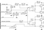
The functional diagram of the analog yaw damper is similar to the functional diagrams of the pitch and roll dampers (Fig. 6.9). The rudder deflection D5E is created by the pilot by moving the pedals Pn by the amount Dxn from the balancing position. Using a differential rocker, this signal is summed with the control signal of the yaw damper A5EP. The steering actuator of the rudder РПьП forms the deflection of the rudder.
Rice. 6.10. Transient processes in the yaw rate contour when the pilot deflects the rudder:
a-free plane; 5-with yaw damper turned on 194
When yaw angular velocity c occurs, the DUS sensor generates an electrical signal ish, proportional to this speed. Calculator B generates a control signal u according to the control law (6.83) to the input of the adder C of the rudder servo drive SPII. The servo drive converts this signal into movement of the rudder steering unit rod D8£р.
The influence of yaw dampers on directional stability and controllability.
Let us show that with the help of a yaw damper the degree of travel is improved.
static stability of the aircraft m When the rudder is deflected by the damper, an increment in the yaw moment coefficient appears
Amy = my"A5;|p = my, k0)coy. (6.85)
Let us take the partial derivative of expression (6.85) with respect to the angular velocity су:
Therefore, with the yaw damper turned on:
i.e., the degree of directional static stability of an aircraft with a yaw damper is higher than the degree of the aircraft’s own directional static stability.
We will show that using a yaw damper improves the dynamic stability of lateral movement. In Fig. 6.10, a presents the transient processes that arise as a result of the pilot’s stepwise deflection of the rudder by an angle D5R. As can be seen from the graphs in Fig. 6.10, b, the yaw damper reduces the oscillation of transient processes in angular velocity and yaw angle - the period of short-period oscillations and the damping time are reduced. Since the rudder deflection by the D6DR damper is subtracted from the rudder deflection by the L8E pilot, the total rudder deflection of the L5N becomes smaller. This leads to a decrease in the steady-state value of the yaw rate of the murst compared to control without a damper, i.e., the efficiency of rudder control from the pedals decreases.
Features of the control laws of yaw dampers. Varieties of yaw dampers are dampers that implement the following control laws:
D5DR = Qyuu =kyuryuu, (6.89)
D5DR = ky—————— soy. (6.90)

In the control law (6.89), the control parameter is the yaw angular acceleration yuy, obtained by differentiating the signal yuy in the DOS. The isodromic filter T^p/(T^p + 1) of the control law (6.90) is implemented in the damper block computer, for example, using a KS chain.
The yaw damper control laws (6.89) and (6.90) make it possible to reduce the adverse effect of the yaw damper on directional control. This is achieved by returning the steering unit rod to the neutral position when yuy = 0, i.e. A5“p = 0 with sorust = const. Therefore, the damper’s resistance to the pilot stops and the rate of pedal movement to create angular velocity does not change. In this case, naturally, the stability characteristics deteriorate.
 |
In addition to reducing the adverse effect on directional control, yaw dampers with control laws (6.89) and (6.90) eliminate the negative consequences of the relationship between yaw and roll movements. Thus, in a steady turn with a roll, the yaw damper with the control law (6.83) counteracts the turn by deflecting the rudder when the angular velocity cov occurs. Constant filtering
component of this speed, the control laws (6.89) and (6.90) allow you to keep the rudder in neutral when making a turn and react only to the oscillation of the angular movement relative to the constant component of the turn speed.
For additional damping of the aircraft during landing, when the speed of the aircraft is low and the effectiveness of the rudder decreases, an additional damping signal proportional to the yaw rate is included in the control law (6.52),
AS?1 = K, ^ w, + F™. K®, (6.91)
where Fa3n takes a value equal to 1 when the automatic approach mode (ALA) is turned on and 0 in all other modes.
The block diagram of the yaw damper implementing the control law (6.91) is shown in Fig. 6.11. In this way, yaw vibrations are damped using the ABSU-154 system.
At low flight speeds, additional yaw damping is required when the aircraft enters a roll and when the ailerons are deflected. Then the control law (6.90) includes additional signals proportional to the roll angle and aileron deflection angle, passed through isodromic filters with time constants Tf and T
A5? = kj———- ^—— ray + F3ai[ C 1————— y+k5z—————- , (6-92)
Tr+ 1 1 T, p+1 TS(p+ 1 ‘
where F, aK takes a value equal to 1 when the flaps are extended at an angle of 30° and 0 when the flaps are retracted.
The GV gyrovertical serves as a signal sensor proportional to the roll angle. The autopilot steering feedback sensor serves as a signal sensor proportional to the aileron deflection angle. The flap extension sensor is a KV8Sh limit switch.
The block diagram of the yaw damper implementing the control law (6.92) is shown in Fig. 6.12. In this way, yaw vibrations are damped using the ASSU-86 system.
The main characteristic of the lateral stability of an aircraft is the degree of static directional stability along the slip angle φ. To increase it and dampen the lateral vibrations of the aircraft in the yaw damper, it is necessary to use a signal proportional to the angular sliding velocity p. However, creating sensors for such a signal is difficult, so the following simplified dependence of the angular sliding velocity p on the angular velocities of yaw and roll in horizontal flight with a constant angle of attack a0 is used:
p = roycosa0 + caxsma0. (6.93)
Consequently, to effectively dampen aircraft oscillations along the sideslip angle, it is necessary to introduce into the yaw damper, in addition to a signal proportional to the yaw angular velocity, a signal proportional to the roll angular velocity. Then the control law takes the following form: ‘
D82р = C——— - “y + k*, ®, (6.94)
The transfer coefficient kffl is adjusted according to the position of the flaps (it takes on a greater value when the flaps are extended and decreases when they are retracted).
The block diagram of the yaw damper implementing the control law (6.95) is shown in Fig. 6.13. This is how yaw vibrations are damped using the yaw damper DR-62.
Yaw damper- an electro-hydraulic device designed to improve the aircraft’s own damping properties in the yaw path channel. Includes yaw rate sensors and a processor that sends a signal to an actuator connected to the steering wheel.
When the aircraft rotates relative to the normal axis, the keel receives an additional speed of movement directed perpendicular to the aircraft's speed vector. Thanks to this additional speed, the direction of the air flow flowing onto the keel changes and an additional lateral force arises, creating a moment that counteracts the rotation that has begun. This moment is called damping, because it appears only when the aircraft is rotating. Damping- the property of a moving body to counteract the resulting rotation. The main reason for installing a yaw damper on an aircraft is to prevent lateral oscillations such as "Dutch roll". This type of lateral movement of an aircraft is characterized by interconnected oscillations in roll and slide. Moreover, sliding oscillations lag behind the roll oscillations in phase, which is associated with weak track and excessive lateral stability. The roll of the aircraft is the cause of the aircraft sliding, the elimination of which occurs with a delay due to weak directional stability. The resulting slip provokes a vigorous roll of the aircraft in the opposite direction due to increased lateral stability, and the process is repeated. When flying at high altitude and low speed, the damping of these vibrations can be greatly degraded. On heavy aircraft, yaw dampers are used to dampen vibrations.
Some aircraft have automatic damping on all three channels (yaw, pitch and roll dampers).
Aeroelastic vibration damper
Aeroelastic oscillation damper is an independent on-board electronic system or subsystem as part of an automatic flight control system (ACS), designed to automatically dampen short-period oscillations of the aircraft that inevitably arise during changes in flight conditions and, most importantly, to prevent involuntary swinging of the aircraft by the pilot, which can lead to to significant overloads and structural failure. In technical terms, it consists of a group of gyroscopic sensors that control the angular movements of the aircraft in space, an electronic circuit for processing and amplifying damping signals and actuators connected in series to the mechanical control wiring, or these signals are mixed with other ACS control signals.
see also
Write a review about the article "Yaw damper"
Links
- . aviacom.ucoz.ru
|
||||||||||||||||||||||||||||||||||
Excerpt describing the Yaw Damper
Of course, it wasn’t written on my face, but I would give a lot to find out how she always knew everything so confidently when it came to me?A few minutes later we were already stomping together towards the forest, enthusiastically chatting about the most diverse and incredible stories, which she, naturally, knew much more than I did, and this was one of the reasons why I loved walking with her so much.
It was just the two of us, and there was no need to be afraid that someone would overhear and someone might not like what we were talking about.
Grandmother very easily accepted all my oddities and was never afraid of anything; and sometimes, if she saw that I was completely “lost” in something, she gave me advice to help me get out of this or that undesirable situation, but most often she simply observed how I reacted to life’s difficulties, which had already become permanent, without finally came across on my “spiked” path. Lately it has begun to seem to me that my grandmother is just waiting for something new to come along, in order to see if I have matured at least a heel, or if I am still “stuck away” in my “happy childhood”, not wanting to get out of my short childhood shirts. But even for her “cruel” behavior, I loved her very much and tried to take advantage of every convenient moment to spend time with her as often as possible.
The forest greeted us with the welcoming rustle of golden autumn leaves. The weather was magnificent, and one could hope that my new friend, by “luck,” would also be there.
I picked a small bouquet of some modest autumn flowers that still remained, and a few minutes later we were already next to the cemetery, at the gate of which... in the same place sat the same miniature sweet old lady...
- And I already thought I couldn’t wait for you! – she greeted joyfully.
My jaw literally dropped from such surprise, and at that moment I apparently looked quite stupid, because the old woman, laughing cheerfully, came up to us and affectionately patted me on the cheek.
- Well, you go, honey, Stella has already been waiting for you. And we'll sit here for a while...
I didn’t even have time to ask how I would get to the same Stella, when everything disappeared again somewhere, and I found myself in the already familiar world of Stella’s wild fantasy, sparkling and shimmering with all the colors of the rainbow, and, without having time to take a better look around, I immediately I heard an enthusiastic voice:
- Oh, how good it is that you came! And I waited and waited!..
The girl flew up to me like a whirlwind and plopped a little red “dragon” right into my arms... I recoiled in surprise, but immediately laughed cheerfully, because it was the funniest and funniest creature in the world!..
“The little dragon,” if you can call him that, bulged his delicate pink belly and hissed at me threateningly, apparently hoping very much to scare me in this way. But when he saw that no one was going to be scared here, he calmly settled down on my lap and began to snore peacefully, showing how good he is and how much he should be loved...