Preheater Teplostar 14t-10 makes it easier to start the engine, increase the resource of the power plant and significantly increase operating comfort in winter. This model is the most common in Russia. This is due to the fact that Teplostar 14ts-10 is supplied to the assembly lines of large enterprises, such as the auto giant OJSC KamAZ. During its existence, Teplostar 14ts-10 has undergone many changes aimed at improving and improving the quality of the heater.
The full set of heater properties includes the following functions:
- Ensuring reliable engine starting at low air temperatures down to -45 o C;
- Additional heating of the engine and interior when the engine is running in severe frost conditions;
- Heated interior and windshield (to remove icing) when the engine is not running;
- Possibility of starting the preheater manually for 3 or 8 hours;
- Timer - optional, remote timer required.
Equipment Teplostar 14TS-10:
- Heater, fuel pump, control panel, installation kit, wiring harnesses, electric circulation pump, 13 l fuel tank.
Operating principle of Teplostar 14TS-10
The operating principle of the Teplostar heater is based on heating the liquid, which is forcibly pumped through the heat exchange system of the heater. To heat the liquid, combustion products of the fuel-air mixture in the combustion chamber are used as a heat source. The heat is transferred through the walls of the heat exchanger to the coolant, which is pumped through the car's engine cooling system.
Universal kit (power – 12-15 kW) with a remote control for automotive vehicles with a diesel engine. Supply voltage 12 V, 24 V.
Diesel heater
14TS-10 is designed for pre-launch heating with a liquid cooling system and heating of the passenger compartment at ambient temperatures down to minus 45°C.
The heater operates independently of the car engine. The heater is powered by electricity from the vehicle.
The heater can be supplied with fuel from the vehicle's fuel tank or from the fuel tank included with the heater.

Operating principle
The operating principle of the heater is based on heating the liquid, which is forcibly pumped through the heat exchange system of the heater.
To heat the liquid, gases from
combustion of the fuel mixture in the combustion chamber. The heat is transferred through the walls of the heat exchanger to the coolant, which is pumped through the car's engine cooling system.
When the heater is turned on, the performance of the heater elements is tested and monitored: flame indicator, sensors
Temperature and overheating, pumps, blower motor, spark plugs,
fuel pump and their electrical circuits. If it is in good condition, the ignition process begins. At the same time, the circulation pump (pump) is turned on.
The heater can operate in one of two programs: “economical” or “pre-start”. The economical program has lower consumption
power.

Control block
a) turning the heater on and off by command from the control panel;
b) initial diagnostics (serviceability check) of the heater components during startup;
c) diagnostics of heater components during the entire operation;
d) start-up and automatic operation according to the “pre-start” or “economy” programs (transition to various modes depending on the temperature of the engine coolant);
e) turning off the heater:
At the end of the specified cycle (cycle 3 hours or 8 hours);
When parameters go beyond acceptable limits (temperature, voltage and flame failure in the combustion chamber).

Remote Control
The control panel (hereinafter referred to as the remote control) is designed for manual control of the heater. The remote control is intended for: - starting and stopping the heater in manual mode; - selection of operating mode; - control of the cabin heater fan; displaying the status of the heater (working, not working, or not working due to a malfunction).
- starting and stopping the heater in manual mode; - selection of operating mode; - control of the cabin heater fan; displaying the status of the heater (working, not working, or not working due to a malfunction).
- control of the cabin heater fan; displaying the status of the heater (working, not working, or not working due to a malfunction).
displaying the status of the heater (working, not working, or not working due to a malfunction).

On the front panel of the remote control there are two key switches, an LED and a thermostat knob. Switches are designed to execute the following commands:
1. to start (position “I”) and turn off the heater (position “O”);
2. to select the pre-start “3” or economical “8” operating mode.
The “pre-start” operating mode is intended to warm up and maintain the engine warm for 3 hours.
The “economy” operating mode is designed to keep the engine and driver’s cabin warm when the engine is not running; the maximum operating time in this mode is 8 hours.

The thermostat knob is used to control the cabin heater fan (provided that the coolant temperature is more than 55°C and the cabin heater switch on the panel in the cabin is in the position
"OFF", vehicle weight on) as follows:
a) when the thermostat knob is set to the extreme left position, the cabin heater fan will be turned off;
b) when the thermostat knob is set to the extreme right position, the cabin heater fan will operate continuously;
c) when installing the thermostat knob between the extreme positions
the fan will turn on cyclically. Cycle duration is 10 minutes.
For example, if the knob is set to a position in which the heater fan will work for 4 minutes, and only after 6 minutes it will turn on again for 4 minutes, etc. Thus, it will work until the position of the thermostat knob is changed or until the heater is turned off. After each change in the position of the thermostat knob (between the extreme positions), the next switching on of the cabin heater fan will occur in the interval from 2 to 8 minutes.

Control panel design and operation
- does not light - when the heater is not working.
- does not light - when the heater is not working.


Diesel pre-heaters 20TS and 20TS-D38
Universal kit (power - 20 kW) with a remote control for automotive vehicles and buses with a diesel engine. Supply voltage 24 V.

Diesel heater 20TS-D38 is designed for pre-heating of a diesel engine with a liquid cooling system and heating the passenger compartment at ambient temperatures down to minus 45°C.
The full set of heater properties includes the following functions:
1 Ensuring reliable engine starting at low air temperatures;
2 Additional engine reheating and interior heating when the engine is running in severe frost conditions;
3 Heating of the interior and windshield (to remove icing) when the engine is not running;
4 Pump operation when the heater is not working

Purpose and scope
When the heater is turned on, testing and control is carried out
the operability of the heater elements: flame indicator, temperature and overheating sensors, pump, air blower electric motor, spark plug, fuel pump and their electrical circuits. If it is in good condition, the ignition process begins. At the same time, the circulation pump (pump) is turned on.
According to a given program, the chamber is pre-purged
combustion and heating the glow plug to the required temperature. Then fuel and air begin to flow. The combustion process begins in the combustion chamber. The combustion of the fuel mixture in the combustion chamber is controlled by a flame indicator. All processes during the operation of the heater are controlled by the control unit.
The control unit controls the coolant temperature
liquid, and depending on its size sets the appropriate
combustion power. The higher the liquid temperature, the lower the combustion power. The temperature of the coolant at the outlet of the heater is set in the range from 30 to 80 °C using the thermostat knob, which
located on the control panel. When the liquid is heated above 85°C, the heater switches to the “cooling” mode, the combustion process stops, and the pump continues to operate to ensure liquid circulation in the vehicle’s interior heating system. When cooling the liquid
15°C below the set temperature (using the PU knob), the heater automatically starts working.

Heater control
Heater control unit (CU)
The control unit provides control of the heater together with the control panel.
The control unit performs the following functions:
a) initial diagnostics (serviceability check) of the heater components when
b) diagnostics of heater components during the entire operation;
c) startup and automatic operation depending on the temperature of the coolant at the outlet of the heater;
d) turning off the heater:
At the end of the specified cycle (8 hours);
If one of the monitored nodes fails;
When parameters go beyond acceptable limits (coolant temperature, voltage);
When the flame fails in the combustion chamber.

Control panel design and operation
On the front panel of the remote control there are two key switches, a thermostat and an LED.
Switches are designed to execute the following commands:
To start (position “ | “) and shutdown
heater (position “O”);
To turn on the pump (position “P”) and
turning off the pump (position “O”) when the heater is not working.
The thermostat knob is used to set the temperature of the coolant at the outlet of the heater in the range from 30 to 80 °C.
The LED shows the status of the heater:
Lights up - when the heater is operating;
Flashing - in case of a malfunction (accident). The number of flashes after a pause corresponds to the fault code.
Does not light - when the heater is not working


Gas pre-heater Teplostar 15TSG
Gas pre-heater 15TSG, designed for heating
engine with a liquid cooling system running on compressed
natural gas at ambient temperatures down to minus 45°C.
![]()
The full set of heater properties includes the following functions: 1 Ensuring reliable engine starting at low air temperatures. 2 Additional heating of the engine and interior when the engine is running in severe frost conditions. 3 Heating of the interior and windshield (to remove icing) when the engine is not running. 4 Possibility of starting in manual mode for 3 or 8 hours of operation with simultaneous installation of the “economical” or “normal” operating program on the control panel.
Compressed natural gas has fire and explosive properties.
Persons who have undergone appropriate training, passed an exam on the technical minimum and safety rules, and received a certificate of the established form are allowed to drive cars equipped with gas cylinder equipment (LPG) and a gas heater.
A driver who takes part in the maintenance and repair of gas-cylinder vehicles must undergo preliminary safety training for workers when servicing and repairing gas equipment and 15TSG.
The driver is the responsible person for compliance with safety rules by all persons in the car and is obliged to require them to comply with these rules.
Those found guilty of violating these instructions will be held accountable.

Description of the heater operation
The heater operates independently of the car engine.
The heater is supplied with compressed gas from gas cylinder equipment (LPG) installed on the vehicle. Electricity is supplied from the vehicle.
The heater is an autonomous heating device that contains:
- heater;
- the low pressure unit serves to supply gas at a certain flow rate to the combustion chamber. The block is installed on the heater body;
- filter for gas purification (built into the low pressure unit);
- circulation pump (pump) for forced pumping of working fluid
cooling systems (antifreeze) through the heat exchange system of the heater; - a control unit that controls the above-listed devices according to one of the specified programs “normal” or “economical”;
- the control panel together with the control unit provides control of the heater;
- wiring harness for connecting the elements of the heater, gas equipment and vehicle battery.
- a control unit that controls the above-listed devices according to one of the specified programs “normal” or “economical”;
- the control panel together with the control unit provides control of the heater;
- wiring harness for connecting the elements of the heater, gas equipment and vehicle battery.

Description of the heater operation
In the “small” mode, the coolant heats up to 80°C (both
The control unit monitors the coolant temperature and, depending on the coolant temperature, sets the heater operating modes: “full”, “small” or “cooling”. In the “full” mode, according to the “normal” program, the coolant is heated to 70°C, in the “economy” program to 60°C, and when heated above 70°C or 60°C, respectively, it switches to the “small” mode.
programs), and when heated above 80°C, it switches to the “cooling” mode, which stops the combustion process, the pump continues to operate and heat the car interior. When the liquid is cooled below 55°C according to the “normal” and “economy” programs, the heater automatically turns on again to the “full” mode. The duration of a full operating cycle is 3 hours or 8 hours depending on the position of the switch on the control panel. In addition, it is possible to turn off the heater at any time during the cycle.
When a command is given to turn off the heater manually or automatically according to the program, the gas supply is stopped and the combustion chamber is purged with air

Main parameters and characteristics
Main technical characteristics of heaters, technical characteristics are given with a tolerance of ±10%, obtained at a temperature of 20°C and rated voltage.

Malfunctions of the pre-heater 14TS-10, which can be eliminated on your own.
Preheater 14TS-10 does not start after switching on, you must:
- Check the presence of fuel in the tank;
- Check fuses:
- 5A - the heater does not start, the LED on the remote control does not light up;
- 25A - the heater does not start, the LED on the remote control does not light up.
All other heater malfunctions that occur are automatically indicated by a blinking LED on the remote control.
In case of any malfunctions that arise during operation, except for those specified in clause 7.1, you must contact a repair shop.
Malfunctions of heater control system elements
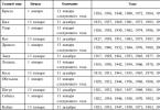
Troubleshooting must begin by checking the contacts of the connectors of the circuits being tested (see. table 1 And ).
Table 1
All other heater malfunctions that have occurred are shown in Table 2.
table 2
|
Quantity |
Description of the malfunction |
A comment. |
|
Overheat Possible identified |
The overheating sensor or temperature sensor produces a temperature above 102°C. Difference in temperature values measured by the overheating sensor and the sensor |
|
|
Launch attempts |
If the allowed number of startup attempts has been used - |
|
|
Interrupt |
Check the quantity and supply of fuel. |
|
|
Malfunction Motor malfunction |
Check glow plug, replace if necessary Check the electrical wiring of the air blower motor, |
|
|
Malfunction |
Check the ohmic resistance between the contacts of the indicator connector. |
|
|
Sensor malfunction Sensor malfunction |
Check connecting wires. |
|
|
Malfunction Malfunction |
Check the electrical wires of the circulation pump for shorts Check the fuel pump electrical wires for shorts |
|
|
Relay fault |
Check the electrical wires of the relay, eliminate the short circuit, |
|
|
No connection between |
Check connecting wires, connectors |
|
|
Disconnection, |
Check the battery, regulator and electrical supply wiring. |
|
|
Disconnection, |
Check the battery, regulator and electrical supply wiring. |
|
|
Time exceeded |
|
CODE-01 Overheating Possible detected
overheat. The temperature difference between the overheating sensor and the temperature sensor is too large
Trouble-shooting
The overheating sensor or temperature sensor reports a temperature above 102°C. Check the complete fluid circuit and the operation of the circulation pump.
The difference in temperature values measured by the overheating sensor and the temperature sensor is more than 20°C (the temperature value from the overheating sensor is more than 85°C or the temperature sensor is more than 70°C). Check the overheating sensor and temperature sensor and replace if necessary.
Check the operation of the circulation pump..
CODE-02 Attempts to start the system scoops
Trouble-shooting
If the permissible number of starting attempts has been used, check the quantity and supply of fuel. Check the combustion air supply system and the exhaust pipe.
CODE-03 Flame interruption
Trouble-shooting
Check the quantity and supply of fuel. Check the combustion air supply system and the exhaust pipe. If the heater starts, check the flame indicator and replace if necessary. Check the fine fuel filter for clogging
CODE-04 Glow plug malfunction
Blower motor malfunction
Trouble-shooting
Check the glow plug and replace if necessary.
Check the electrical wiring of the air blower motor, if necessary, replace the air blower
CODE-05 Flame indicator fault
Trouble-shooting
Check connecting wires. Check the ohmic resistance between the contacts of the indicator connector. If there is a break, the ohmic resistance is more than 90 ohms. If broken, replace the flame indicator.
Check the ohmic resistance between the contacts of the indicator connector. During a short circuit, the ohmic resistance is less than 10 ohms. If there is a short circuit, replace the flame indicator.
CODE-06 Overheat sensor malfunction
Temperature sensor malfunction
Trouble-shooting
Check connecting wires. The output signal and voltage are linearly dependent on temperature (0°C corresponds to 2.73 V and with an increase in temperature by 1°C, the output signal correspondingly increases by 10 mV). Check the sensor and replace if necessary.
CODE-07 Circulation pump malfunction
Fuel pump malfunction
Trouble-shooting
Check the electrical wires of the circulation pump for short circuits, check the circulation pump and replace if necessary.
Check the fuel pump electrical wires for short circuits, check the fuel pump for performance and replace if necessary.
CODE-09 Shutdown, overvoltage
Shutdown, undervoltage
Trouble-shooting
Check the battery, regulator and electrical supply wiring. The voltage between pins 4 and 7 of the XS1 connector should be no higher than 30 V.
Check the battery, regulator and electrical supply wiring. The voltage between pins 4 and 7 of the XS1 connector must be at least 20 V
CODE-10 Ventilation time exceeded
Trouble-shooting
During purging, the heater is not cooled sufficiently.
Check the combustion air supply and exhaust pipe. Check the flame indicator and replace if necessary. 
A biological sewage treatment plant is a sewage system that purifies wastewater up to 98%. Advantages of stations...
Today, to warm up a car engine in winter, mainly two solutions are used - alarms with auto start and pre-heaters. Which of these solutions is better? Read about the advantages and disadvantages of different approaches to warming up the engine and what to choose.
The main advantage is that the engine is always heated, but at the same time it is not subjected to stress due to frequent starting, which prolongs its service life. However, the heater is quite expensive, and besides, it constantly discharges the battery, and if you do not start the engine after heating, the battery may be completely discharged, and this will not lead to anything good. Another advantage of the heater is efficiency. Its use significantly saves fuel, which also leads to some reduction in financial costs. Features and advantages of alarms with auto-start Alarms with auto-start are a more affordable and simpler solution that both protects the car and warms up the engine during long-term parking. Such systems can operate either in automatic mode, starting the engine by a timer or by an outside air temperature sensor, or in manual mode, starting the engine upon command from the key fob. An alarm system with auto start has an undoubted advantage - it isEngine pre-heaters and air heaters "Advers"
In this article we would like to introduce you to the products of the Advers company, which manufactures engine pre-heaters and air heaters.
The action of the pre-heater is as follows: first of all, it is a heat exchanger, inside of which the combustion chamber is located; air is supplied to the chamber using a blower under pressure; fuel also gets there using a metering pump. In order to ensure constant intensive circulation of liquid through the heat exchanger body or the vehicle’s liquid circuit, an additional pump is installed on the pre-heater. The control unit is responsible for the operation of the preheater. The control unit contains all the information about what modes and how long the pre-heater worked. The processes of its operation are controlled by the control unit. It sets the operating modes of the preheater. The preheater can operate in three modes. As mentioned above, “Advers” pre-heaters are divided into those that are supplied directly to vans, buses, trucks, special equipment, and those that provide engine heatingAutonomous liquid preheater for trucks Teplostar 14TS-10-BCH 12V
TEPLOSTAR 14TS-10, 20TS, 15TSG are new models of pre-starting autonomous liquid heaters with a power of 12-20 kW, intended for buses and trucks that run on diesel fuel or compressed natural gas. Such heaters provide warming up of the vehicle engine and interior during the cold season.
The main advantages of cars with the TEPLOSTAR heater installed:
Guaranteed starting of the vehicle engine at low temperatures (up to -45°C);
When the engine is not running, it is possible to heat the car interior;
Elimination of cold starting of the vehicle engine, which, in turn, extends the engine life;
When the engine is warm, fuel is saved;
The joint operation of the car engine and the pre-heater increases the efficiency of the vehicle heating system.
Brief job description
Heater diagram Teplostar 14TS-10
The autonomous liquid heater Teplostar 14TS-10 is designed for preheating engine coolant in the cold season. The installed heater is connected to the vehicle’s fuel and cooling systems and to the on-board power supply. The engine heater is started manually using a control device. When started, the heater pump supplies fuel to the combustion chamber, where a fuel-air mixture is formed, ignited by the glow pin. The resulting thermal energy through the heat exchanger heats the coolant, which passes through the small engine circuit due to the operation of the heater fluid pump. When the coolant heats up to 85 degrees, the heater goes into low power mode. Your car is warmed up and ready to go!
Teplostar can be used with a running engine while driving. In this case, the heater heats the engine coolant to operating temperature.
Kit contents
The kit includes: auxiliary heater, 13L fuel tank, control panel, fuel pump, liquid pump, installation kit (fasteners, electrical wiring kit, hoses, connectors, fuel line, air intake, exhaust kit), documentation, warranty card.
Principle of operation
Autonomous engine pre-heater Teplostar 14TS-10 12 is designed to warm up a cold engine before starting. The operating principle of the Teplostar 14TS-10 12 heater is based on heating the liquid in the engine cooling system, which is forcibly pumped through the heat exchange system of the heater. The heat released during combustion of the fuel mixture in the combustion chamber, transmitted through the walls of the heat exchanger, warms up the coolant, which circulates in the vehicle’s cooling system. The Teplostar 14TS-10 12 engine heater can operate in economy mode or in pre-start mode. In Eco mode, power consumption is reduced.
According to a given program, the combustion chamber is pre-purged and the glow plug is heated to the required temperature. The candle turns on for 90 seconds. Then fuel and air are supplied. The combustion process begins in the combustion chamber. The flame indicator monitors the combustion process of the fuel mixture in the combustion chamber. All processes during the operation of the heater are coordinated and controlled by the control unit.
The Teplostar 14TS-10 12 control unit controls the coolant temperature and, depending on its temperature, selects the heater operating modes: “full”, “medium” or “small”. In the “full” mode, according to the “pre-start” program, the coolant is heated to 70°C, according to the “economy” program - up to 55°C, and when heated above 70°C or 55°C, respectively, it switches to the “medium” mode. In the “medium” mode, according to the “pre-start” or “economy” programs, the coolant is heated to a temperature of 75°C, and when heated above 75°C, the Teplostar 14TS-10 switches to the “small” mode. In the “small” mode, the coolant heats up to 80°C (in both programs), and when heated above 80°C it goes into cooling mode, the combustion process stops, the pump continues to operate and the car interior is heated. When the liquid is cooled below 55°C under the “pre-start” program, the heater automatically turns on again to the “full” mode, and under the “economy” program - to the “medium” mode.
The duration of a full cycle of operation of Teplostar 14TS-10 12 under the “pre-start” program is 3 hours, under the “economical” program 8 hours. You can turn off the engine liquid heater at any time during the cycle if desired.
Characteristic Meaning
Heating capacity 15.5 kW - max., 9 kW - medium, 4 kW - small.
Voltage 12V
Fuel Diesel
Fuel consumption max. 2.0, min. 0.54l/h
Heater power consumption 86W (max), 31W (min)
Coolant Antifreeze, antifreeze
Control Manual
Dimensions LxHxW 440x259x175
Set weight 16 kg