Once upon a time, audio amplifiers (ULF) were large, with a bunch of tubes, huge radiators for transistors, and heavy transformers in the power supply. But life does not stand still. Now compact microcircuits with digital ULF have replaced tube and transistor dinosaurs in almost all consumer devices. You can easily design a compact amplifier, for example on the PAM8610 chip. The power supply from the review was used for power supply.
The ULF on the PAM8610 exists in several versions and is quite inexpensive. For example, you can buy it here -. It was decided to use a ready-made board with a volume control and soldered connectors. There is also an ultra-budget option. It was reviewed here on the website -. Why this particular amplifier - price and very good impressions from the younger models PAM8403/PAM8406: , .
Let's see how the older amplifier model performs.
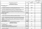
Module characteristics:
Power supply 7-15V, recommended 12V
Power up to 10 W per channel at 8 ohm load resistance
Protection against short circuit, overheating
Amplifier efficiency up to 90%
Judging by the description, excellent characteristics for such a baby.
Photo: 


The flux is a little not completely washed off.
The speaker connections are not indicated in any way. It was found out empirically and using a similar slightly different board: 
Power plug - center "+", around - "-"
The microcircuit under the radiator of this amplifier version is good. Jumpers on the board - one temporarily turns off the sound (mute), the second I don’t know.
To power the structure, it was decided to use the power supply from the link at the beginning of the review. This power supply has been reviewed in great detail. The power supply works well in extreme conditions, is compact and inexpensive. Theoretically, you can get a total power of about 12 watts per two channels with this power supply. Or real about 5 watts per channel. I was satisfied with this power supply and the ULF power. For greater amplification of the microcircuit when using a signal source in the form of a cell phone or DAC, it is necessary to use preliminary amplification in front of the microcircuit, which I did not want to do. And 5 watts of power per channel is enough for my purposes. But we will still test the ULF and PSU microcircuits in different modes and on loads of different resistances.
Power unit: 

To test the load we use powerful resistors 4 Ohm, 6 Ohm, 8 Ohm per 100 Watt: 
You can buy them here
We connect all modules and resistors. 
We take measurements.
The amplifier supply voltage is 12 V, a 1000 Hz signal from a sound generator is supplied to the input. Power is calculated by the square of the voltage at the output of one channel of the amplifier (measured with an AC voltmeter) with a connected load divided by the load resistance
First group of tests
Normal source (phone or DAC). Uin = 0.15 V. Testing was carried out on the power supply from the review, without preliminary amplification. In all cases, the overheating protection on the microcircuit and the current protection on the power supply did not work. 
I have speakers with a resistance of 4 Ohms - the first line is my mode of using the amplifier.
Second group of tests
Disabling the power supply from the current protection review. We increase Uin until the protection on the power supply is triggered. This mode is possible when using a pre-amplifier (for example,) before the amplifier from the review 
Third group of tests
Limit mode. A laboratory power supply is used. The tests are completed if the amplifier chip turns off due to overheating (the temperature of the chip in this case is more than 100 degrees Celsius). In reality, to implement this mode, you need a more powerful power supply (12 V 2 A for example) and preliminary signal amplification. 
I think more power than stated was achieved using a radiator on a ULF chip.
The tests may be useful if you are going to use this ULF chip for your amplifier or make a powerful portable speaker with a preamp and a powerful battery.
Chip heatsink temperature. The radiator here is good. But there are versions of this board without a radiator. 
Temperature at resistors: 
If there is such a temperature here at 9 Watts, then what will happen when testing a 100 Watt amplifier?
Sine wave test. We apply a 1000 Hz sinusoid to the input and use an oscilloscope to see what we have at the output of the amplifier.
18+ Readers with unstable mental health should not watch
Amplifier input: 
Output at very low volume: 
Average volume level: 
Sine wave at maximum. The ULF chip is on the verge of shutting down due to overheating. 
I was surprised by the results - the younger PAM8403/PAM8406 output with a sine wave is ok. Maybe I mixed something up when measuring. I went online and found a video review of a similar microcircuit - . True, your friend there did not connect a load to the output and carried out tests without a preamplifier (he did not bring the microcircuit to its maximum modes).
After completing the tests, I decided to refine everything. Components for assembly:

The router is used as a . I asked for it in the same way as the review. A toggle switch was also made for a regular linear input.
The case was purchased offline for 400 rubles - the cheapest in terms of price-size-quality ratio.

It turned out like this:


Initially, a 12->5 V DC converter based on a PWM controller was installed. But I had to install a second 5V power supply for two reasons:
1. Interference. I removed the ground loops, but some interference (possibly from the converter) remained.
2. In case of overload, the power supply is switched off by protection - the router is overloaded and this is not good - it takes a long time to overload.
Result: 


My mini hi-fi system: 
For my tasks (sounding the bathroom and corridor), the power of the power supply and the sound quality from the ULF are quite enough.
The product was provided for writing a review by the store. The review was published in accordance with clause 18 of the Site Rules.
I'm planning to buy +35 Add to favorites I liked the review +25 +59If your car doesn't have room for a powerful audio system and your car amplifier is out of use, don't give it away or throw it away. It can be used indoors or outdoors; you can use the power supply from your computer to connect it.
WHAT IS THE ARTICLE ABOUT?
Actions
1. Find the power on pin
- The package with the power supply (when purchasing a new one) should contain a pinout diagram. Look for a pin that is labeled like “Power on,” “PS OK,” or other keywords indicating a signal. It will be on the largest connector.
- On new power supplies, 99% of the time this will be a green wire, but for older models (“10+ years”) the wire may be yellow or purple. If your power supply doesn't come with a pinout diagram, check the manufacturer's website for a pinout diagram.

2. Cut the power-on wire from the connector and strip the insulation from the edge

3. Cut the ground wire from the connector and also strip the edge of the insulation

- Refer to the pin diagram to find out what color the ground wire is. 99.9% it will be a black wire.
4. Connect both stripped ends and insulate

5. Connect all 12v wires

stripping their ends together, having previously cut them off from the connector.
- Refer to the pinout diagram to see what color the 12v wires are. In 99.9% of cases these will be yellow wires.
6. Connect all negative wires together, cutting them off from the connector and stripping the ends

- Refer to the pinout diagram to see which color is negative. In 99.9% of cases these will be black wires.
7. Take the twisted yellow 12v wires and attach them to the “+” terminal of the amplifier

- Some amplifiers may simply label "12v" instead of "+".
8. Take the twisted black wires and attach them to the “-” terminal of the amplifier

9. To connect “+” or “12v” to the “REM” or “REMOTE” source on the amplifier, use a discarded piece of wire

10. Connect the signal source, speakers and our power supply to the amplifier
- Now you can plug in the power supply and enjoy the music!

- You can add a switch in step 4. Simply connect both ends of the wire to the switch. This will give you the ability to turn off the power with a button instead of having to unplug and plug in the power source.
Connoisseurs of high-quality and loud sound in the car will certainly be faced with the need to install a car amplifier. Every car enthusiast knows that the power of a car's electrical network is 12 Volts, which is critically low to produce a truly powerful sound with a resistance of 4 Ohms, because some massive speakers are designed to power several thousand watts. In such cases, a power amplifier is additionally installed in the car in order to convert the voltage. If desired, the power amplifier can be made by hand; its circuitry is quite simple. The only difficulty may be to make a power supply for a car amplifier.
Power supply structure
The power supply is the most complex part in the amplifier, which consists of:
- pulse generator;
- field effect transistors IRFZ44N;
- diode VD1,
- ferrite ring with a diameter of at least 2 centimeters;
- throttle L1;
More often than not, it is precisely because of the laboriousness of assembling the unit that many lovers of high-quality sound refuse to assemble a car amplifier themselves. In fact, everything is not as difficult as it might seem initially. It is enough to have minimal knowledge or follow the instructions.
The heart of the converter is conventionally called an electric pulse generator. The simplest formula for its creation is based on the TL494 circuit. The generation frequency can be increased or decreased by changing the rated power of resistor R3.
The power supply muscles for the amplifier are piecemeal transistors of the IRFZ44N type. Resistors of any type can be used in the circuit (with the exception of R4, R9, R10). The power supply can include resistors of any rated power, including 0.125 W, 0.25 W, and including 1 W and even 0.5 W. LED VD1 is mounted in the circuit in order to prevent secondary connection of positive channels.
Making a power supply for an amplifier
The hydraulic choke L1 needs to be screwed onto a ferrite ring with a diameter of 2 cm. It can be borrowed from a computer power supply or simply bought. For a ferrite ring with a diameter of 2 cm, it is necessary to make 12 turns of doubled wire with a cut equal to 0.7 millimeters, which should be evenly distributed along the entire perimeter of the ring. This hydraulic choke is also suitable for winding onto a ferrite rod with a diameter of 8-10 millimeters and a length of 2-3 centimeters. Definitely, the most difficult moment in the manufacture of a voltage converter is the correct molding of the transformer, since the performance of the entire power supply depends on the transformer. The optimal solution would be to make it using a 2000NM ferrite ring with a volume of 40 * 25 * 11.
Perhaps the most difficult part of amplifier design is powering the subwoofer channel from the on-board 12 volt network. There are a lot of reviews about it in various forums, but it is very difficult to make a really good converter using the advice of experts, see for yourself when it comes to this part of the design. To do this, I decided to focus on assembling a voltage converter; perhaps this will be the most detailed description, since it outlines two weeks of work, as people say - from<<А>>to<<Я>>.
There are a lot of voltage converter circuits, but as a rule, after assembly, defects, malfunctions, and incomprehensible overheating of individual parts and parts of the circuit appear. Assembling the converter took me two weeks, since a number of changes were made to the main circuit; in the end, I can safely say that the result was a powerful and reliable converter.
The main task was to build a 300-350 watt converter to power the amplifier according to the Lanzar scheme, everything turned out beautifully and neatly, everything except the board, we have a big shortage of chemicals for etching boards, so we had to use a breadboard, but I don’t advise repeating my torment, soldering Wiring for each track, tinning each hole and contact is not an easy job, this can be judged by looking at the back of the board. For a beautiful appearance, wide green tape was glued to the board.
PULSE TRANSFORMER
The main change in the circuit is the pulse transformer. In almost all articles on homemade subwoofer installations, the transformer is made on ferrite rings, but the rings are sometimes not available (as in my case). The only thing that was there was an Alsifer ring from a high-frequency choke, but the operating frequency of this ring did not allow it to be used as a transformer in a voltage converter.

Here I was lucky, I received a couple of computer power supplies almost for nothing; fortunately, both units had completely identical transformers.

As a result, it was decided to use two transformers as one, although one such transformer can provide the desired power, but when winding the windings simply would not fit, so it was decided to remake both transformers.

First, you need to remove the heart; in fact, the work is quite simple. Using a lighter, we heat the ferrite stick, which closes the main heart, and after 30 seconds of heating, the glue melts and the ferrite stick falls out. The properties of the stick may change due to overheating, but this is not so important, since we will not use sticks in the main transformer.

We do the same with the second transformer, then we remove all the standard windings, clean the transformer terminals and cut off one of the side walls of both transformers, it is advisable to cut down the wall free from contacts.

The next part of the work is gluing the frames. You can simply wrap the fastening area (seam) with electrical tape or tape; I do not recommend using various adhesives, as this may interfere with the insertion of the core.

I had experience in assembling voltage converters, but nevertheless this converter cost me all the juice and money, since during the work 8 field workers were killed and the transformer was to blame for everything.
Experiments with the number of turns, winding technology and wire cross-sections led to pleasing results.
So the hardest part is winding. Many forums advise winding a thick primary, but experience has shown that you don’t need much to get the specified power. The primary winding consists of two completely identical windings, each of them is wound with 5 strands of 0.8 mm wire, stretched along the entire length of the frame, but we won’t rush. To begin with, we take a wire with a diameter of 0.8 mm, the wire is preferably new and smooth, without bends (although I used a wire from the network winding of the same transformers from power supplies).

Next, we wind 5 turns along one wire along the entire length of the transformer frame (you can also wind all the wires together with a bundle). After winding the first core, it needs to be strengthened by simply winding it onto the side terminals of the transformer. Afterwards we wind the rest of the wires, evenly and neatly. After winding is completed, you need to get rid of the varnish coating on the ends of the winding; this can be done in several ways - heat the wires with a powerful soldering iron or remove the varnish individually from each wire with a mounting knife or razor. After this, you need to tin the ends of the wires, weave them into a pigtail (it’s convenient to use pliers) and cover them with a thick layer of tin.
After this, we move on to the second half of the primary winding. It is completely identical to the first one; before winding it, we cover the first part of the winding with electrical tape. The second half of the primary winding is also stretched across the entire frame and wound in the same direction as the first; we wind it according to the same principle, one core at a time.

After winding is completed, the windings need to be phased. We should get one winding, which consists of 10 turns and has a tap from the middle. It is important to remember one important detail here - the end of the first half should join with the beginning of the second half or vice versa, so that there are no difficulties with phasing, it is better to do everything from photographs.
After a lot of hard work, the primary winding is finally ready! (you can drink beer).
The secondary winding also requires a lot of attention, since it is this that will power the amplifier. It is wound according to the same principle as the primary, only each half consists of 12 turns, which completely ensures a bipolar output voltage of 50-55 volts.

The winding consists of two halves, each is wound with 3 strands of 0.8 mm wire, the wires are stretched throughout the frame. After winding the first half, we insulate the winding and wind the second half on top in the same direction as the first. As a result, we get two identical halves, which are phased in the same way as the primary. Afterwards, the leads are cleaned, intertwined and sealed to each other.

One important point - if you decide to use other types of transformers, then make sure that the halves of the heart do not have a gap; as a result of experiments, it was found that even the slightest gap of 0.1 mm sharply disrupts the operation of the circuit, the current consumption increases by 3-4 times , the field-effect transistors begin to overheat so that the cooler does not have time to cool them.

The finished transformer can be shielded with copper foil, but this does not play a particularly big role.

The result is a compact transformer that can easily deliver the required power.
The circuit diagram of the device is not simple; I do not advise novice radio amateurs to contact it. The basis, as always, is a pulse generator built on the TL494 integrated circuit. The additional output amplifier is built on a pair of low-power transistors of the BC 557 series, almost a complete analogue of the BC556; from the domestic interior, you can use the KT3107. Two pairs of powerful field-effect transistors of the IRF3205 series are used as power switches, 2 field-effect transistors per arm.

The transistors are installed on small heat sinks from computer power supplies and are pre-insulated from the heat sink with a special gasket.
The 51 ohm resistor is the only part of the circuit that overheats, so a 2-watt resistor is needed (although I only have 1 watt), but overheating is not terrible, it does not affect the operation of the circuit in any way.
Installation, especially on a breadboard, is a very tedious process, so it’s better to do everything on a printed circuit board. We make the plus and minus tracks wider, then cover them with thick layers of tin, since a considerable current will flow through them, the same with the field drains.
We set 22 ohm resistors at 0.5-1 watt, they are designed to remove overload from the microcircuit.

The field gate current limiting resistors and the microcircuit supply current limiting resistor (10 ohm) are preferably half a watt, all other resistors can be 0.125 watt.

The frequency of the converter is set using a 1.2nf capacitor and a 15k resistor; by decreasing the capacitance of the capacitor and increasing the resistance of the resistor, you can increase the frequency or vice versa, but it is advisable not to play with the frequency, since the operation of the entire circuit may be disrupted.
The rectifier diodes were used in the KD213A series; they did the best job, because due to the operating frequency (100 kHz) they felt excellent, although you can use any high-speed diodes with a current of at least 10 amperes; it is also possible to use Schottky diode assemblies, which can be found in the same computer power supplies, in one case there are 2 diodes that have a common cathode, so for a diode bridge you will need 3 such diode assemblies. Another diode is installed to power the circuit; this diode serves as protection against power overload.

Unfortunately, I have capacitors with a voltage of 35 volts of 3300 microfarads, but it is better to select a voltage from 50 to 63 volts. There are two such capacitors per arm.
The circuit uses 3 chokes, the first to power the converter circuit. This inductor can be wound on standard yellow rings from power supplies. We wind 10 turns evenly around the entire ring, the wire is divided into two 1 mm wires.


Chokes for filtering RF interference after the transformer also contain 10 turns, wire with a diameter of 1-1.5 mm, wound on the same rings or on ferrite rods of any brand (the diameter of the rods is not critical, length 2-4 cm).
The converter is powered when the Remote Control (REM) wire is connected to the power supply positive, this closes the relay and the converter starts working. I used two relays connected in parallel at 25 amps each.

The coolers are soldered onto the converter block and turn on immediately after the REM wire is turned on. One of them is designed to cool the converter, the other is for the amplifier, you can also install one of the coolers in the opposite direction so that the latter removes warm air from the common case.
RESULTS AND COSTS
Well, what can I say, the converter justified all hopes and costs, it works like a clock. As a result of the experiments, he was able to deliver an honest 500 watts and would have been able to do more if the diode bridge of the unit that powered the converter had not died.
Total spent on the converter (prices shown are for the total number of parts, not for one)
IRF3205 4pcs - 5$
TL494 1pc -0.5$
BC557 3pcs - 1$
KD213A 4pcs - 4$
Capacitors 35V 3300uF 4pcs - $3
Resistor 51 ohm 1 piece - $0.1
Resistor 22 ohm 2 pcs -0.15$
Development board - $1


From this list, I got the diodes and capacitors for free, I think except for the field workers and the microcircuit, everything can be found in the attic, asked from friends or in workshops, so the price of the converter does not exceed $10. You can buy a ready-made Chinese amplifier for a subwoofer with all the amenities for $80-100, and products from well-known companies cost a lot, from $300 to $1000. In return, you can assemble an amplifier of identical quality for only $50-60, even less if you know where to get the parts from , I hope I was able to answer many questions.