Error codes for KamAZ Euro-4 are information about problems in the operation of the vehicle.
How to diagnose
Diagnostics includes collecting signs of problems in the system, scanning the electronic control system, resetting and checking all mechanisms and systems for faults in the electronic unit, inspecting all sensors that are responsible for the uninterrupted operation of the power unit.
During diagnostics of KamAZ-5490, 54115, 5308 and other models with an engine manufactured according to the international environmental standards Euro-3 and 4, the pressure level in the fuel system is measured, the performance of the generator set is tested and exhaust gases are analyzed using special equipment. They also check the winding of the electromagnetic regulator of the fuel supply system and the short circuit in the inductive sensor coils.
Equipment and programs for diagnostics
There are several scanners for detecting problems in vehicle mechanisms, for example:
- Autoscanner DK-5. This equipment helps detect problems in the electronic unit by reading and adjusting control system indicators using a computer. This autoscanner can be used at temperatures up to +30°C and relative humidity no more than 80%.
- Scanner EDS-24. This is a software and hardware complex designed for computer diagnostics of a cargo vehicle. It includes a USB adapter with galvanic isolation, which makes it possible to test systems in low voltage conditions.
Diagnostic programs:
- Euroscan;
- Scanmatik-2;
- AVTOAS-CARGO.

Decoding errors
The decoding of KamAZ error codes is presented in the instructions for the program, which is used for diagnostics. Examples of errors:
- 213 - malfunction of the power unit control device;
- 296 - oil pressure has dropped;
- 2973 - failures in the air pressure control system in the intake manifold;
- 214 - overheating of the oil fluid;
- 235 - insufficient amount of coolant in the system;
- 425 - high oil temperature;
- 3617 - there is no signal from the multi-stage switch;
- error 4335 - problems with air supply;
- 275 - fuel injection pump is not working correctly;
- 429 - high voltage in the fuel indicator circuit;
- 351 - malfunction of the injectors;
- 415 - low level of working fluid;
- 261 - fuel overheating.
See » All about the repair and installation of a brake valve for KamAZ

Sensor failures
Fault codes for KamAZ-34334, 6308 and other models with Euro-4 engines:
- 221 - a breakdown in the pedal position sensor, which is responsible for the supply of working fluid;
- 232 - malfunction of the sensor measuring atmospheric pressure;
- 335 - defects in the wiring of the lamp control output stage;
- 231 - malfunction of the boost pressure sensor on the electrical control unit;
- 124 — fixing an incorrect voltage indicator;
- 345 - incorrect operation of signal transmission from the exhaust gas pressure indicator;
- 113 - problems with camshaft speed;
- 112 - incorrect indicators supplied to the control unit from the crankshaft;
- 246 - malfunction of the temperature sensor;
- 00550 - malfunction of the fuel injection pump plug.

ICE malfunctions
List of internal combustion engine breakdowns on KamAZ:
- 726 FMI 2 - malfunction of the position indicator of the device responsible for liquid distribution;
- SPN 526313 FMI 6 - defective device that controls the pressure level in the ramp mechanism;
- SPN 520211 FMI 12 - no message from the ABS system;
- SPN 791 FMI 4 - low charge level;
- 523470-2 - there is no voltage in the circuit of the mechanism responsible for resetting the pressure indicators;
- SPN 523613 FMI 16 - working fluid filters are worn out;
- 77 FMI 0 - high engine speed;
- 190-3 - malfunction;
- 110-0 — high level of motor temperature;
- 132-4 - failure in air flow distribution;
- 653-0 - damage to the injector power supply system.

Other breakdowns
Code table:
| System error codes | Cause of failure |
| SPN 977 FMI 4 | Malfunctions in the operation of the air conditioner chain mechanism |
| 98-1 | The number of crankshaft revolutions has been exceeded |
| 523601-4 | Low fuel and oil level |
| 3514-31 | The power supply has failed |
| 675-4 | Injectors are closed |
| 13688-4 | Fuel pump relay shorted to ground |
| 91-4 | Fuzzy signal from the sensor responsible for the position of the brake mechanism |
| 171-3 | This error stands for a malfunction of the thermometer |
| 1072-4 | The valve was shorted to ground |
| 111-3 | Strong signal from the antifreeze level indicator |
| 1188-5 | There is no connection with the air flow heating relay |
| 110-2 | The sensor monitoring the antifreeze temperature is not working correctly |
| 1188-4 | There is a short to ground in the pressure valve control circuit. |
In accordance with Euro 4 environmental standards, new engines began to be installed on cars of the Kama Automobile Plant in 2013. Compliance with such stringent standards was achieved thanks to the introduction of an electronic engine control system into the power units. This made it possible to carry out early diagnosis of faults, which are now displayed on the instrument panel as KamAZ Euro 4 error codes.
[Hide]
Car diagnostics
Before the advent of electronic engine control units (ECUs), Kama truck drivers had to determine problems with their vehicles based on their own experience. The number of errors during such “diagnosis” was very large until the introduction of ECUs in KamAZ engines. This makes troubleshooting much easier.
If the car has some kind of malfunction, even if it is not visible visually, then a check light lights up on the instrument panel.
What ECU models are equipped with KAMAZ trucks?
Every KamAZ 6520 Euro 4 driver needs to know that engines of this brand use only two ECU models:
- Bosch MS6.1;
- ISB CM 2150.
The Bosch MS6.1 control unit is installed on the following motors:
- 740.64-420;
- 740.63-400;
- 740.60-360;
- 740.61-320;
- 740.62-280;
- 740.65-240;
- 820.73-300;
- 820.72-240;
- 820.74-300;
- 820.60-260.
The ISB CM 2150 control unit is used on a larger number of powertrain models;
- 740.64-420;
- 740.63-400;
- 740.60-360;
- 740.61-320;
- 740.62-280;
- 740.65-240;
- 740.75-440;
- 740.74-420;
- 740.73-400;
- 740.72-360;
- 740.71-320;
- 740.70-280.
How to diagnose yourself?
Many drivers are afraid to diagnose KamAZ 43253 Euro 4 with their own hands. There is nothing complicated in this procedure and it is carried out quite simply.
Each electronic unit model uses its own error marking. It is necessary to perform self-diagnosis on KamAZ 65115 Cummins Euro-4 and obtain error codes for each ECU for further decoding.
On vehicles with a Bosch ECU, self-diagnosis of KamAZ 43118 Euro-4 occurs as follows:
- When you start the engine, the “Check” should light up for three seconds and go out, along with the oil pressure and battery charging lights. This means that the system is working.
- If the signal icon does not go out, it means that the system has detected a malfunction.
- It remains to find out what is wrong with your KamAZ. For this, the truck has a special button, it is located either on the left under the steering wheel or next to the fuse box.
Location of the "Check" button
You don’t need anything else to independently diagnose a car, but at specialized service stations, a special scanner is used to speed up diagnostics.
Equipment and programs for diagnostics of KamAZ Euro 4
At truck service stations, the AVTOAS-CARGO diagnostic scanner is used to diagnose trucks.
On KamAZ vehicles, using this scanner you can diagnose the following engines:
- Cummins 4ISBe, 6ISBe, CM2150C (Euro-3);
- Cummins 4ISBe, 6ISBe, CM2150E (Euro-4);
- KamAZ 740 E3, BOSCH MS 6.1;
- KamAZ 740 E4, BOSCH EDC7UC31;
- YaMZ 656 E3, Elara 50.3763;
- YaMZ 656 E3, M230. E3.
To connect the scanner with a personal computer, an element such as the “ECU-Link 3” adapter is used.
The software required to work with the AUTOAS-CARGO scanner is included with the scanner on a CD. The program can be downloaded to tablets and smartphones from the official website of the manufacturer.
Error codes for engines with BOSCH ECUs
You can get the error code using the button:
- under the steering wheel;
- on the fuse panel.
If you use the button under the steering wheel, then it has an up and down position, while the button itself is in a neutral and middle position.
To obtain a fault code, you must:
- For 2 seconds, hold down the button, either in the lower or upper position.
- By blinking the “Check” icon on the instrument panel, determine the malfunction, which is expressed by a code.
- The number of glares with long intervals shows the first digit of the code, the number of glares with short intervals shows the second.

KAMAZ Euro 4 error code recognition scheme. In this case, the code is 24
- 11 – the gas pedal is faulty, with this fault the engine does not develop more than 1900 rpm;
- 12, 13 – atmospheric pressure sensor is faulty;
- 14 – clutch malfunction, with this malfunction the engine does not develop more than 1900 rpm;
- 15 – incorrect operation of the crankshaft; with this malfunction, the engine does not develop more than 1600 rpm;
- 16, 17 – incorrect operation of frequency rotation sensors; with this malfunction, the engine does not develop more than 1800 rpm;
- 18 – incorrect operation of the camshaft; with this malfunction, the engine does not develop more than 1800 rpm;
- 19 – main relay malfunction;
- 21, 22, 24–26 – malfunction of the high pressure fuel pump, with this malfunction the engine does not start;
- 23 – incorrect position of the gas and brake pedals;
- 27 – steering rack malfunction, with this malfunction the car will also not start;
- 28 – brake malfunction;
- 29, 51–53, 81–86, 99 – incorrect operation of the electronic control unit, in this case you will also not be able to start your truck;
- 31, 32 – incorrect operation of the air temperature sensor;
- 33, 34 – incorrect operation of the air pressure sensor;
- 35 – malfunction of cruise control;
- 36, 37 – the machine either overheats, or vice versa, does not reach operating temperature;
- 38, 39 – fuel does not reach operating temperature;
- 41 – the signal from the multi-stage input does not correspond to the reference one;
- 42 – permissible engine speed exceeded;
- 43 – incorrect operation of the speedometer;
- 54 – increased voltage in the on-board network;
- 55 – incorrect operation of the control unit;
- 61–67 – incorrect operation of the CAN controller network; it is this system that is responsible for the correct operation of the anti-lock braking system (ABS).
Error codes for engines with ECU ISB CM2150
This is a newer control unit than BOSCH MS 6.1; it is the ISB CM2150 system that is installed on new car engines from Naberezhnye Chelny. These cars are equipped with two “Check” indicators - yellow and red. If the error light is yellow, this means that you can drive the car, but if the light turns red, then your problem does not allow you to drive independently.
This system has three-digit or four-digit error codes. But they are obtained in the same way as in the previous case.
- 111 – incorrect operation of the engine control module;
- 115 – incorrect operation of the engine speed sensor;
- 143 – oil pressure has decreased;
- 146 – coolant overheating;
- 151 – the coolant does not reach operating temperature;
- 197 – insufficient coolant;
- 214 – oil overheating;
- 233 – coolant pressure is reduced, the pump is faulty;
- 234 – high engine speed;
- 235 – insufficient coolant;
- 245 – voltage in the fan control circuit is reduced;
- 261 – increased fuel temperature;
- 275 – the fuel pump is not working correctly;
- 281 – the high pressure valve is not working correctly;
- 351 – error in the operation of the injector power supply;
- 415 – insufficient oil pressure;
- 422 – insufficient coolant;
- 425 – oil temperature exceeded;
- 428 – incorrect;
- 429 – increased voltage in the fuel sensor circuit;
- 431 – error in the idle circuit;
- 432 – does not work correctly;
- 433 – insufficient fuel pressure;
- 434 – network power disappeared after turning off the engine;
- 435 – insufficient oil pressure;
- 441 – insufficient battery charging;
- 442 – battery recharge;
- 449 – increased fuel pressure;
- 595 – turbocharging speed exceeded;
- 596 – incorrect operation of the generator, high voltage;
- 598 – insufficient voltage in the generator circuit;
- 687 – low turbocharger speed
- 689 – error in the operation of the engine speed sensor;
- 1139 – incorrect operation of injector No. 1;
- 1141 – incorrect operation of injector No. 2;
- 1142 – incorrect operation of injector No. 3;
- 1143 – incorrect operation of injector No. 4;
- 1144 – incorrect operation of injector No. 5;
- 1145 – incorrect operation of injector No. 6;
- 2265 – the starting pump is not working correctly, the voltage is higher than normal;
- 2266 – the starting pump is not working correctly, the voltage is below normal;
- 2292 – the fuel metering device does not work correctly;
- 2293 – the fuel metering device does not work correctly;
- 2377 – the voltage in the fan control circuit is exceeded;
- 2555 – in the incoming air heating system the voltage is higher than normal;
- 2556 – in the incoming air heating system, the voltage is below normal;
- 2558 – voltage below normal in the auxiliary starting device circuit;
- 2973 – incorrect operation of the pressure sensor in the intake manifold.
The above-described method of receiving errors is called the method using blink codes (taking data from blinking “Check” indicators). More detailed data can be obtained using computer equipment. There, error codes are displayed on the screen in the format “SPN number, FMI number”.
A list of errors and malfunctions in this format, there are many more of them than when diagnosing using blink codes:
- SPN 94 FMI 1 – insufficient pressure in the low pressure fuel circuit;
- SPN 94 FMI 0 – excessive pressure in the low pressure fuel circuit;
- SPN 106 FMI 4 – insufficient signal from the air pressure sensor in the manifold;
- SPN 106 FMI 3 – signal from the manifold air pressure sensor is too strong;
- SPN 132 FMI 4 – the signal from the air flow sensor is too weak;
- SPN 132 FMI 3 – the signal from the air flow sensor is too strong;
- SPN 190 FMI 4 – weak signal with ;
- SPN 723 FMI 4 – weak signal from the camshaft sensor;
- SPN 105 FMI 4 – weak signal from the air temperature sensor in the manifold;
- SPN 105 FMI 3 – signal from the manifold air temperature sensor is too strong;
- SPN 629 FMI 12 – malfunction in the control unit;
- SPN 523613 FMI 7 – malfunction of the rail pressure control valve;
- SPN 108 FMI 4 – weak signal from the atmospheric pressure sensor;
- SPN 108 FMI 3 – signal from the atmospheric pressure sensor is too strong;
- SPN 523470 FMI 11 – malfunction of the pressure relief valve in the rail;
- SPN 174 FMI 16 – fuel temperature is too high;
- SPN 110 FMI 4 – weak signal from the antifreeze temperature sensor;
- SPN 110 FMI 3 – the signal from the antifreeze temperature sensor is too strong;
- SPN 110 FMI 18 – power unit temperature is too high;
- SPN 520224 FMI 12 – error in the control unit;
- SPN 520223 FMI 11 – control unit reset error;
- SPN 3050 FMI 1 – poor performance of the exhaust gas converter;
- SPN 3050 FMI 19 – no signal is received from the SCR system;
- SPN 190 FMI 8 – crankshaft position sensor is not synchronized;
- SPN 190 FMI 5 – failure of the crankshaft position sensor;
- SPN 723 FMI 8 – incorrect operation of the camshaft position sensor;
- SPN 723 FMI 2 – incorrect operation of the camshaft position sensor;
- SPN 723 FMI 5 – no signal is received from the camshaft position sensor;
- SPN 84 FMI 11 – speed sensor is faulty;
- SPN 110 FMI 0 – excessive engine temperature;
- SPN 172 FMI 0 – excessive air temperature in the intake manifold;
- SPN 74 FMI 0 – excessively high engine speed;
- SPN 2634 FMI 5 – no current in the main relay circuit;
- SPN 2634 FMI 4 – short circuit to ground of the main relay circuit;
- SPN 2634 FMI 3 – short to power in the main relay circuit;
- SPN 1351 FMI 5 – lack of current in the air conditioner relay circuit;
- SPN 1351 FMI 4 – air conditioner relay circuit short to ground;
- SPN 1351 FMI 3 – short to power in the air conditioner relay circuit;
- SPN 1213 FMI 5 – no current in the “CHECK ENGINE” circuit;
- SPN 1213 FMI 4 – short to ground in the “CHECK ENGINE” circuit;
- SPN 1213 FMI 3 – short to power in the “CHECK ENGINE” circuit;
- SPN 94 FMI 4 – weak signal from the low pressure fuel sensor;
- SPN 94 FMI 3 – signal from the low pressure fuel sensor is too strong;
- SPN 91 FMI 13 – incorrect signal from track 1 of the gas pedal position sensor;
- SPN 29 FMI 13 – incorrect signal from track 2 of the gas pedal position sensor;
- SPN 158 FMI 1 – insufficient voltage in the on-board circuit;
- SPN 158 FMI 0 – excessive voltage in the on-board circuit;
- SPN 651 FMI 5 – failure of the injector of cylinder 1;
- SPN 651 FMI 4 – ground fault of injector 1 cylinder;
- SPN 651 FMI 3 – Short to power supply to injector 1 cylinder;
- SPN 652 FMI 5 – failure of the injector of cylinder 2;
- SPN 652 FMI 4 – cylinder 2 injector short circuit to ground;
- SPN 652 FMI 3 – Short to power supply to injector 2 of cylinder;
- SPN 653 FMI 5 – failure of cylinder 3 injector;
- SPN 653 FMI 4 – cylinder 3 injector short circuit to ground;
- SPN 653 FMI 3 – short to power supply to injector 3 of cylinder;
- SPN 654 FMI 5 – failure of the 4th cylinder injector;
- SPN 654 FMI 4 – cylinder 4 injector short circuit to ground;
- SPN 654 FMI 3 – short to power supply to the injector of cylinder 4;
- SPN 2791 FMI 5 – no voltage in the EGR valve circuit;
- SPN 2791 FMI 4 – short to ground in the EGR valve circuit;
- SPN 2791 FMI 3 – short to ground in the EGR valve circuit;
- SPN 523470 FMI 5 – no voltage in the pressure relief valve circuit;
- SPN 523470 FMI 4 – short to ground in the pressure relief valve circuit;
- SPN 523470 FMI 3 – short to ground in the pressure relief valve circuit;
- SPN 630 FMI 12 – malfunction of the RAM control unit;
- SPN 628 FMI 12 – malfunction of the ROM control unit;
- SPN 1188 FMI 5 – there is no voltage in the turbocharger pressure valve regulator circuit;
- SPN 1188 FMI 4 – short to ground in the turbocharger pressure valve regulator circuit;
- SPN 1188 FMI 3 – short to ground in the turbocharger pressure valve regulator circuit;
- SPN 523613 FMI 5 – there is no voltage in the circuit leading to the ramp regulator valve;
- SPN 523613 FMI 4 – short to ground in the circuit leading to the ramp regulator valve;
- SPN 523613 FMI 3 – short to ground in the circuit leading to the ramp regulator valve;
- SPN 977 FMI 5 – no voltage in the fan relay circuit;
- SPN 977 FMI 4 – short to ground in the fan relay circuit;
- SPN 977 FMI 3 – short to ground in the fan relay;
- SPN 645 FMI 5 – there is no voltage in the tachometer circuit;
- SPN 645 FMI 4 – short to ground in the tachometer circuit;
- SPN 645 FMI 3 – short to ground in the tachometer circuit;
- SPN 107 FMI 16 – air filter needs to be replaced;
- SPN 98 FMI 4 – poor signal from the oil pressure sensor;
- SPN 98 FMI 3 – signal from the oil pressure sensor is too strong;
- SPN 157 FMI 4 – poor signal from the fuel pressure sensor in the rail;
- SPN 157 FMI 3 – signal from the fuel pressure sensor in the rail is too strong;
- SPN 157 FMI 1 – insufficient fuel pressure in the rail;
- SPN 157 FMI 0 – excessive fuel pressure in the rail;
- SPN 639 FMI 19 – the automatic transmission controller circuit is broken;
- SPN 91 FMI 2 – gear sensor tracks are incorrectly located;
- SPN 1136 FMI 12 – the temperature sensor in the controller is faulty;
- SPN 523601 FMI 4 – weak signal from the refrigerant pressure sensor;
- SPN 523601 FMI 3 – signal from the refrigerant pressure sensor is too strong;
- SPN 1321 FMI 5 – no connection with the starter interlock relay;
- SPN 1321 FMI 4 – starter interlock relay is shorted to ground;
- SPN 1321 FMI 3 – starter interlock relay is shorted to power;
- SPN 3509 FMI 31 – 5V failure in the power supply of sensors 1
- SPN 3510 FMI 31 – 5V failure in the power supply of sensors 2
- SPN 3511 FMI 31 – 5V failure in the power supply of sensors 3
- SPN 3512 FMI 31 – 5V failure in the power supply of sensors 4
- SPN 3513 FMI 31 – 5V failure in the power supply of sensors 5
- SPN 3514 FMI 31 – the 12 V sensor power supply is faulty;
- SPN 106 FMI 2 – air pressure sensor does not work correctly;
- SPN 110 FMI 2 – antifreeze temperature sensor does not work correctly;
- SPN 173 FMI 0 – excessive antifreeze temperature;
- SPN 175 FMI 0 – excessive oil temperature;
- SPN 174 FMI 0 – excessive fuel temperature;
- SPN 174 FMI 4 – weak signal from the fuel temperature sensor;
- SPN 174 FMI 3 – signal from the fuel temperature sensor is too strong;
- SPN 596 FMI 4 – weak signal from the CC control knob;
- SPN 596 FMI 3 – signal from the CC control knob is too strong;
- SPN 655 FMI 5 – failure of the cylinder 5 injector;
- SPN 655 FMI 4 – injector of cylinder 5 is shorted to ground;
- SPN 655 FMI 3 – injector of cylinder 5 is short-circuited to power;
- SPN 656 FMI 5 – failure of the 6th cylinder injector;
- SPN 656 FMI 4 – injector of cylinder 6 is shorted to ground;
- SPN 656 FMI 3 – injector of cylinder 6 is shorted to power;
- SPN 657 FMI 5 – failure of the cylinder 7 injector;
- SPN 657 FMI 4 – injector of cylinder 7 is shorted to ground;
- SPN 657 FMI 3 – injector of cylinder 7 is shorted to power;
- SPN 658 FMI 5 – failure of the 8th cylinder injector;
- SPN 658 FMI 4 – injector of cylinder 8 is shorted to ground;
- SPN 658 FMI 3 – injector of cylinder 8 is shorted to power;
- SPN 1347 FMI 5 – no connection with the fuel pump relay;
- SPN 1347 FMI 4 – fuel pump relay is shorted to ground;
- SPN 1347 FMI 3 – fuel pump relay is shorted to power;
- SPN 3050 FMI 15 – exhaust gas converter is faulty;
- SPN 3050 FMI 0 – exhaust gas converter is faulty;
- SPN 729 FMI 5 – no connection with the air heating relay;
- SPN 729 FMI 4 – air heating relay is shorted to ground;
- SPN 729 FMI 3 – air heating relay is shorted to power;
- SPN 1188 FMI 5 – no connection with exhaust gas bypass valve-1;
- SPN 1188 FMI 4 – exhaust gas bypass valve-1 is shorted to ground;
- SPN 1188 FMI 3 – exhaust gas bypass valve-1 is shorted to power;
- SPN 1189 FMI 5 – no connection with exhaust gas bypass valve-2;
- SPN 1189 FMI 4 – exhaust gas bypass valve-2 is shorted to ground;
- SPN 1189 FMI 3 – exhaust gas bypass valve-2 is shorted to power;
- SPN 91 FMI 4 – poor signal from the pedal position sensor;
- SPN 1137 FMI 15 – overheating via TOG channel No. 1;
- SPN 1138 FMI 15 – overheating via TOG channel No. 2;
- SPN 190 FMI 12 – high resistance of DPKV;
- SPN 723 FMI 12 – high resistance DPRV;
- SPN 1137 FMI 4 – weak signal from TOG sensor No. 1;
- SPN 1137 FMI 3 – strong signal from TOG sensor No. 1;
- SPN 1138 FMI 4 – weak signal from TOG sensor No. 2;
- SPN 1138 FMI 3 – strong signal from TOG sensor No. 2;
- SPN 171 FMI 4 – weak signal from the ambient temperature sensor;
- SPN 171 FMI 3 – strong signal from the ambient temperature sensor;
- SPN 29 FMI 4 – weak signal from pedal position sensor 2;
- SPN 29 FMI 3 – strong signal from pedal position sensor 2;
- SPN 29 FMI 5 – failure of pedal position sensor 1;
- SPN 91 FMI 5 – failure of pedal position sensor 2;
- SPN 1318 FMI 14 – inconsistent operation of TOG sensors No. 1 and TOG No. 2;
- SPN 175 FMI 16 – the oil temperature in the power unit is too high;
- SPN 175 FMI 4 – weak signal from the power unit;
- SPN 175 FMI 3 – signal from the oil temperature sensor in the power unit is too strong;
- SPN 100 FMI 1 – low oil pressure;
- SPN 1072 FMI 5 – no connection with the engine brake valve;
- SPN 1072 FMI 4 – engine brake valve is shorted to ground;
- SPN 1072 FMI 3 – engine brake valve is shorted to power;
- SPN 84 FMI 0 – the vehicle has exceeded the technically permissible speed;
- SPN 102 FMI 0 – turbocharger pressure too high;
- SPN 100 FMI 4 – weak signal from the oil pressure sensor;
- SPN 100 FMI 3 – signal from the oil pressure sensor is too strong;
- SPN 110 FMI 5 – no connection with;
- SPN 172 FMI 5 – failure of the air temperature sensor in the manifold;
- SPN 174 FMI 5 – failure of the fuel temperature sensor;
- SPN 175 FMI 5 – failure of the oil temperature sensor;
- SPN 111 FMI 4 – weak signal from the antifreeze level sensor;
- SPN 111 FMI 3 – signal from the antifreeze level sensor is too strong;
- SPN 723 FMI 3 – strong signal from the camshaft position sensor.
Sometimes on forums you can come across a question about what kind of error is SPN 791, SPN 520211 or SPN 4335. In the list of errors for KamAZ 65117, or KamAZ Euro 4 Cummins 4336, and other models, there are no such codes. The reason for their appearance may lie in the fact that drivers incorrectly removed data from the ECU or the truck has some kind of non-serial electronic system.
How to reset errors on KamAZ Euro 4
Quite often, a situation occurs when, during diagnostics, you consider that the breakdown is insignificant and no repairs are required yet, since it does not affect the operation. However, its presence imposes some restrictions on the operation of the car: it may not start, or the engine speed may be limited.
ENGINE CONTROL SYSTEMS
Engines use fuel control systems with mechanical or electronic regulators (see Table 1).
The mechanical regulators of in-line injection pumps from BOSCH used in Euro-2 engines are built into the pump; their controls are shown in Figure 39.
ELECTRONIC CONTROL SYSTEM
KAMAZ engines of Euro-3 level are equipped with electronic engine control systems (ECM), where instead of traditional fuel injection pumps with a mechanical regulator, the following are used:
BOSCH fuel injection pump type 7100 with electronic regulator;
Fuel injection pump of JSC "YAZDA" type 337-23 with an electronic regulator.
The ECM is designed to control the cyclic fuel supply of the engine depending on the operating modes of the engine, its temperature state, control characteristics and environmental parameters. The system provides the following functions:
Normalization of starting fuel supply;
Correction of cyclic supply depending on charge air pressure;
Limiting the cyclic fuel supply when the maximum coolant temperature is reached;
Starter interlock relay control;
Shutting off the fuel supply in the “mountain brake” mode;
Cruise control function;
Limiting the maximum speed of the vehicle;
Providing emergency engine stop;
Implementation of diagnostic functions and transmission of diagnostic information through the diagnostic connector via K-line and CAN;
Indication of ECM malfunction by the “Check Engine” warning lamp;
Ensuring interaction with other vehicle control systems;
Providing emergency warning and protection, etc.
The full list of functions performed by the ECM is determined when designing the product on which the engine is used.
The ECM includes:
Electronic control unit (ECU);
Wire harnesses complete with sensors, switches and connectors for connecting system diagnostic devices under operating conditions;
Actuators (injection pump rack drive, engine emergency stop valve).
ECM elements and their purpose on KAMAZ engines with fuel injection pump type R7100.
The placement of system elements and the routing of the engine wiring harness are shown in Figure 44.
The system uses the following elements:
Engine speed sensors (main and auxiliary)0 281 002 898 f. "Bosch" induction, used to measure the speed of rotation of the crankshaft and camshaft of the engine. The crankshaft speed measurement sensor is installed in a hole made in the front cover. To generate sensor signals, a special front counterweight of the crankshaft with eight slots is used as an inductor.
The camshaft speed sensor is installed in a special hole made in the flywheel housing. To generate sensor signals, a special wheel with sixteen slots is used as an inductor.
0 281 002 209 Bosch f. is used to determine the temperature state of the engine. Installed in the hole in the engine cooling system thermostat box. The sensor signal is used in the function of limiting the cyclic supply when the permissible engine temperature is exceeded, issuing a warning to the diagnostic lamp and adjusting the starting fuel supply depending on the temperature state of the engine.
Fuel temperature sensor0 281 002 209 f. “Bosch” is used to determine the fuel temperature, mounted in a special valve body installed at the inlet of the injection pump. Depending on its signal, the volume of cyclic fuel supply is adjusted.
Charge air pressure and temperature sensor0 281 002 576 "Bosch", installed in the connecting pipe, determines the temperature and air pressure in the engine intake manifolds. Temperature and air pressure values are necessary to determine the air mass flow.
Electronic control unitMS6.1 from Bosch provides reception and processing of signals from sensors and switches, information transmitted via the CAN bus. The ECU analyzes all incoming information about operating parameters, the state of the engine and the vehicle, processes it in accordance with specified algorithms and controls the fuel injection pump rack, while ensuring the injection of strictly metered portions of fuel. Via the CAN bus, signals can be exchanged with other vehicle systems, and system diagnostics are carried out via K-line.
The electronic control unit is installed in the vehicle cabin.
The actuators of the system are the fuel injection pump rack movement electromagnet and the 24V retractor solenoid of the engine emergency stop valve.
Injection pump rack electromagnetwith a position sensor are used to set the fuel injection pump rack to a position corresponding to the specified engine operating mode. The design and characteristics of the electromagnet provide high accuracy and speed, providing control of the motor depending on operating conditions.
Retractor electromagnet24V of the engine emergency stop valve is used to stop the supply of fuel to the injection pump in the event of emergency situations (for example, jamming of the injection pump rack, excessive crankshaft speed, etc.). Installed in a special valve body together with a fuel temperature sensor.
Fuel pedalThe "TeleAexMorse" function is installed in the cabin of the product and serves to select the required engine operating mode by the driver. The output voltage signal is transmitted to the electronic control unit, where it is converted into a cyclic fuel supply value.
Diagnostic indicator lampengine (“Check Engine” lamp), installed on the instrument panel in the vehicle’s cabin, serves to monitor engine operation and issue fault codes - blink codes.
After turning on the ignition, the engine diagnostic lamp is tested, during which it lights up for three seconds. If the diagnostic lamp remains on or it lights up when the engine is running, this means that a malfunction has occurred in the ECM and to fix it you need to contact a service center. Fault information is stored in the ECU and can be read either using a diagnostic tool or a diagnostic lamp. After the fault is eliminated, the diagnostic lamp goes out.
Rice. 44 - Installing the wiring harness:
1 - crankshaft speed sensor (main), 2 - camshaft speed sensor (auxiliary), 3 - coolant temperature sensor, 4 - fuel temperature sensor, 5 - charge air pressure and temperature sensor, 6 - engine control system harness , 7 - fuel injection pump rack electromagnet, 8 - 24V retractor solenoid of the emergency stop valve
Engine diagnostics.
The diagnostic mode switch installed in the cabin of the product has three positions - middle (fixed), upper and lower (non-fixed). In the up and down positions, the electronic engine control unit is in diagnostic mode.
Engine diagnostics are carried out by pressing and holding the switch in the upper or lower pressed position for more than 2 seconds. After releasing the switch, the diagnostic lamp flashes the engine malfunction blink code in the form of several long flashes (the first character of the blink code) and several short flashes (the second character of the blink code).
The next time you press the switch, the lamp will flash the blink code of the next fault. In this way, all faults stored in the electronic unit are displayed. After displaying the last stored fault, the unit begins to display the first fault again.
To erase the blink codes of faults displayed by the diagnostic lamp from the memory of the control unit, with the diagnostic mode switch pressed, turn on the ignition and then hold the diagnostic mode switch for about 5 seconds.
Example- if there is a physical error in the charge air temperature sensor (blink code 32), the diagnostic lamp will flash 3 long flashes, a pause, 2 short flashes.

The list of possible errors and malfunctions, their pancake codes and recommended actions is given in Table 4
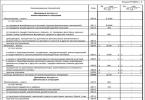
Table 4 - Possible malfunctions, their codes and solutions
|
Description of the error |
Blink code |
How to resolve the error |
|
|
Gas pedal malfunction |
n max =1900min -1 |
Check the gas pedal connection. Contact the service center |
|
|
Atmospheric pressure sensor malfunction |
N max =300 hp |
||
|
Physical error of the atmospheric pressure sensor |
|||
|
Clutch sensor malfunction |
n max=1900min -1 |
Check the clutch sensor. You can continue moving. Do not use the cruise control function. Contact the service center. |
|
|
Malfunction of the main engine speed sensor (crankshaft) |
n max=1600min -1 |
Check the condition and connection of the relevant engine speed sensors |
Continuation of table 4
|
Description of the error |
Blink code |
Limitations set by the ECM |
Method for eliminating the error. |
|
Incorrect polarity or reversal of speed sensors |
n max=1800min -1 n max=1900min -1 |
You can continue moving. Contact the service center |
|
|
Malfunction of auxiliary engine speed sensor (camshaft) |
18 |
n max=1800min -1 |
|
|
Main relay fault |
19 |
No |
Check the main relay and its connection. You can continue moving. Contact the service center. |
|
Fuel injection pump malfunction |
21,22,24-26 |
The engine may not start |
Check the contact of the injection pump plug. Contact the service center immediately! |
|
Description of the error |
Blink code |
Limitations set by the ECM |
How to resolve the error |
|
Inconsistency between the position of the gas pedal and the brake pedal |
23 |
N max =200 hp |
Check the gas pedal, it may be stuck, |
|
Poor contact of the rack position sensor |
27 |
Check the contact of the injection pump plug. Contact the service center immediately |
|
|
Brake pedal sensor malfunction |
28 |
N max =200 hp |
Check the brake pedal sensor and brake relay. You can continue moving. Contact the service center |
|
Malfunction of the electronic control unit (hardware) |
29,51-53,81-86,99 |
The engine may not start. |
Contact the service center immediately |
|
Charge air temperature sensor malfunction |
31 |
N max =300 hp |
Check charge air temperature sensor. You can continue moving. Contact the service center |
|
Charge air temperature sensor physical error |
32 | ||
|
Charge air pressure sensor malfunction |
33 |
N max =250 hp |
Check the charge air pressure sensor.You can continue moving. Contact the service center |
|
Charge air pressure sensor physical error |
34 | ||
|
Cruise control module malfunction |
35 |
No |
Check the connection of the cruise control lever. You can continue moving. Contact the service center. This error also appears due to the simultaneous pressing of several control elements of the cruise control lever |
Continuation of table 4
|
Description of the error |
Blink code |
Limitations set by the ECM |
How to resolve the error |
|
Coolant temperature sensor malfunction |
N max =300 hp n max=1900min -1 |
Check the coolant temperature sensor. You can continue moving. Contact the service center |
|
|
Physical error of the coolant temperature sensor |
|||
|
Fuel temperature sensor malfunction |
n max=1900min -1 |
Check the fuel temperature sensor.You can continue moving. Contact the service center |
|
|
Physical error of the fuel temperature sensor |
|||
|
Description of the error |
Blink code |
Limitations set by the ECM |
How to resolve the error |
|
Incorrect signal from multi-stage input |
No |
You can continue moving. Contact the service center. |
|
|
Vehicle speed signal error |
n max=1550min -1 |
Check the connection of the tachograph to the electronic control unit. You can continue moving. Contact the service center |
|
|
Exceeding on-board voltage |
No |
Check battery charging. |
|
|
Exceeding the maximum permissible engine speed |
After a complete stop of the engine, a new start is possible |
If the excess occurs due to incorrect gear shifting from high to low: check the engine tel; If the engine is in order, you can start the engine and continue driving. If the engine spontaneously increases speed, do not start the engine.Contact the service center immediately |
|
|
Incorrectly completed work cycle of the electronic control unit |
No |
This error appears due to the mass being turned off earlier than 5 seconds after the ignition is turned off or the power supply to the electronic control unit is interrupted. You can continue moving. Contact the service center |
|
|
CAN line fault |
61-76 |
No |
Check the connection of the CAN line to other CAN devices (ABS, automatic transmission, etc.). You can continue moving. Contact the service center |
ECM elements of KAMAZ engines with V-shaped injection pump.
Sensors installed on the engine:
Two crankshaft speed sensors;
Coolant temperature;
Fuel temperatures;
Charge air temperatures;
Charge air pressure.
Engine speed sensor406.3847060-01 (JSC Pegasus) - induction, used to measure the engine crankshaft speed. Installed in special holes in the flywheel housing. To generate crankshaft rotation speed signals, the teeth of the flywheel rim are used as an inductor. To ensure engine operation when one of the sensors fails, two rotation speed sensors are used.
Coolant temperature sensor192.3828 (JSC Avtoelektronika, Kaluga) is used and installed similarly to an ECM with a BOSCH in-line pump.
Fuel temperature sensor192.3828 (JSC Avtoelektronika, Kaluga) installed in the fuel channel of the injection pump, used to determine the fuel temperature. Depending on its signal, the volume of cyclic fuel supply is adjusted.
Charge air temperature sensor192.3828 (JSC Avtoelektronika, Kaluga), installed in the connecting pipe, determines the air temperature in the engine intake manifolds.
Charge air pressure sensor23.3855 (JSC Avtoelektronika, Kaluga) is mounted using a bracket on the connecting pipe of the engine air manifolds and is connected to the intake manifold using a rubber hose.
The values of temperature and air pressure are necessary to determine the mass air flow and, accordingly, the composition of the working mixture.
Electronic control unit50.3763 (JSC ChNPPP Elara, Cheboksary) is installed in the car cabin.
The ECU analyzes all incoming information about operating parameters, the state of the engine and the vehicle, processes it in accordance with specified algorithms and controls the fuel injection pump rack, while ensuring the injection of strictly metered portions of fuel. Via the CAN bus, signals can be exchanged with other vehicle systems, and system diagnostics are carried out via K-line.
Rotary electromagnet for moving fuel injection pump racks(LLC "Rodina Association", Yoshkar-Ola) 18 (Figure 38) with position sensor 17 are used to install the fuel injection pump rails in a position corresponding to the specified engine operating mode. The actuator is bolted to the top cover of the injection pump from the oil cavity side. An actuator position sensor is installed on the outside of the cover. The upper cover of the injection pump is bolted to the pump body through a gasket and ensures the tightness of the oil cavity of the pump. The design and characteristics of the electromagnet determine high accuracy and speed, ensuring regulation of the diesel engine depending on operating conditions.
Fuel shut-off valve,designed to stop the engine by stopping the supply of fuel to the injection pump in the event of emergency situations (for example, exceeding the crankshaft speed), installed in the fuel system at the inlet to the injection pump.
Pedal moduleKDBA 453621.003 (JSC Avtokomlekt, Arzamas) is necessary for the driver to select the required engine operating mode. The output voltage signal is transmitted to the electronic control unit, where it is converted into the required cyclic fuel supply value.
The placement of system elements and the routing of the motor wire bundle on the engine are shown in Figure 45.
Engine diagnostic warning lamp(Check Engine lamp), as in other systems, serves to monitor engine operation and issue fault codes - blink codes.
Diagnosis and management of ECM system errors.
System diagnostics are carried out using a scanner tester or a personal computer. In this case, the OBD II error codes shown in Table 5 are generated.
Some errors can be diagnosed even in the absence of a scanner-tester, for which you need to briefly press the “Diagnostics/Error Reset” button on the product control panel once. If there are errors in the system, the first error code will be displayed using a light bulb (Check Engine light). To determine the next error code, after finishing displaying the current error, press the “Diagnostics/Reset Errors” button on the control panel again, etc.
Each code consists of eight consecutive flashes of varying durations of the light bulb. A short blink (about 0.2 seconds) corresponds to “0”, a long blink (0.6 seconds) corresponds to “1”. Supported codes are listed in the “Blink” field of Table 5. The first blink corresponds to the right digit of the numbers given.
Table 5 - Possible faults and their codes
|
Description of the error |
Blink code |
|
|
OBDII |
Blink |
|
|
Engine speed sensor failure |
P0725 |
00000 000 |
|
Speed sensor signal high |
P0726 |
00000 001 |
|
Failure of the fuel injection pump speed sensor |
P0720 |
00001 000 |
|
High signal level of the fuel injection pump speed sensor |
P0721 |
00001 001 |
|
Low signal level of rack position sensor A |
P1222 |
00011 000 |
|
High signal level of rack position sensor A |
P1223 |
00011 001 |
|
Rack position sensor signal failure A |
P1220 |
00011 010 |
|
Low signal level of rack position sensor B |
P1227 |
00010 000 |
|
High signal level of rack position sensor B |
P1228 |
00010 001 |
|
Rack B position sensor signal failure |
P1225 |
00100 010 |
|
Low signal level of pedal position sensor A |
P0222 |
00110 000 |
|
High signal level of pedal position sensor A |
P0223 |
00110 001 |
|
Pedal Position Sensor A Signal Failure |
P0220 |
00110010 |
|
Low signal level of pedal position sensor B |
P0227 |
00111 000 |
|
Pedal position sensor B signal high |
P0228 |
00111 001 |
|
Pedal Position Sensor B Signal Failure |
P0225 |
00111 010 |
|
High boost pressure sensor signal level |
P0108 |
01000 001 |
|
Boost pressure sensor signal failure |
P0105 |
01000 010 |
|
Charge air temperature sensor signal low |
P0112 |
01010 000 |
|
Charge air temperature sensor signal high |
P0113 |
01010 001 |
|
P0110 |
01010010 |
|
|
Low signal level of the fuel temperature sensor |
P0182 |
01011 000 |
|
High level of fuel temperature sensor signal |
P0183 |
01011 001 |
|
Charge air temperature sensor signal failure |
P0180 |
01011 010 |
|
Coolant temperature sensor signal low |
P0117 |
01100 000 |
|
High signal level of the coolant temperature sensor |
P0118 |
01100 001 |
|
Coolant temperature sensor signal failure |
P0115 |
01100 010 |
|
Low signal level of the supply voltage sensor |
P0562 |
01110 000 |
|
High signal level of the supply voltage sensor |
P0563 |
01110001 |
|
Power supply voltage sensor signal failure |
P0560 |
01110010 |
|
Low voltage level in the sensor power circuit |
P1252 |
10001 000 |
|
High voltage level in the sensor power circuit |
P1253 |
10001 001 |
|
Exceeding emergency speed |
P0219 |
10010 000 |
Continuation of table 5
|
Initial data initialization error |
P0603 |
10010 001 |
|
Initial system testing error |
P1902 |
10010 010 |
|
EEPROM read error |
P1800 |
10011 000 |
|
EEPROM write error |
P1801 |
10011 001 |
|
EEPROM data error |
P1802 |
10011 010 |
|
EEPROM data version mismatch |
P1803 |
10011 011 |
|
The rack control key is not responding |
P1810 |
10100 000 |
|
Exceeding the temperature of the rack control key |
P1811 |
10100 001 |
|
No supply voltage on the rack control key |
P1812 |
10100010 |
|
Output shorted / no load on rack control key |
P1813 |
10100011 |
Table 6 provides detailed descriptions of the main errors, their types, possible causes and methods of elimination.
Error types:
Warning - information error, does not entail any
changes in software operating algorithms;Critical - an error in which the continuation of normal
operation of the system is impossible, leading to forced engine shutdown.Table 6 - Possible malfunctions and methods for eliminating them
|
Cause of occurrence |
Elimination method |
Error type |
|
Error “Frequency sensor signal failure” - no signal |
||
|
Check sensor connection |
warning |
|
|
Sensor is faulty |
Replace sensor |
|
|
Error “High level of frequency sensor signal” - exceeding the permissible value |
||
|
Change sensor setting |
warning |
|
|
Incorrect sensor installation |
Check sensor installation (gap, rotation angle) |
|
|
Sensor is faulty |
Replace sensor |
|
|
Error "Low or high signal level of the ADC sensor"position sensors for racks, pedals, pressure and temperature, supply voltage) |
||
|
Incorrect sensor setting |
Change sensor setup or calibration |
warning |
|
Incorrect sensor installation |
Check the connection and installation of the sensor |
|
|
Sensor is faulty |
Replace sensor |
|
|
Error “ADC sensor signal failure” - no signal (dposition sensors for racks, pedals, pressure and temperature, supply voltage) |
||
|
No sensor |
Install sensor |
Warning, rack position sensor - critical |
|
Shorting the sensor contacts to ground or to power |
Fix the problem |
|
|
Sensor is faulty |
Replace sensor |
|
|
Error “Low voltage level in the sensor power supply circuit” - power failure |
||
|
Low supply voltage |
Check voltage |
critical |
|
Sensor is faulty |
Replace sensor |
|
Continuation of the table. 6
|
Cause of occurrence |
Elimination method |
Error type |
|
Error “High voltage level in the sensor power circuit” - power failure |
||
|
High supply voltage |
Check voltage |
critical |
|
Sensor is faulty |
Replace sensor |
|
|
Error “Emergency crankshaft speed exceeded” |
||
|
Incorrect setting |
Check settings: Emergency speed; Speed controller algorithms; Speed sensors, position of the fuel injection pump actuator |
critical |
|
Error "Initial data initialization failed" |
||
|
Mismatch between the current program version and EEPROM data |
critical |
|
|
Error: "Initial system testing failed" |
||
|
There is a signal from the crankshaft speed sensor |
Stop the engine before turning on the ESU |
critical |
|
Necessary sensors are disabled in the settings |
Check the settings of the rotation speed sensors, the position of the fuel injection pump actuator, and the pedal position |
|
|
There are no signals from the necessary sensors |
Check the rotation speed sensors for the position of the injection pump actuator and the pedal position. Replace sensors if necessary |
|
|
Incorrect setting |
Check the settings of the position sensor of the injection pump actuator, position regulator, control signal |
|
|
Error "EEPROM write error - when saving data Error "EEPROM read error - while reading data |
||
|
ESU unit is faulty |
Replace block |
warning |
|
Error: EEPROM data error Error "Data version mismatch in EEPROM - when reading data |
||
|
EEPROM data error |
Update data in EEPROM |
warning |
|
ESU unit is faulty |
Replace block |
|
|
Error “The rack control key does not respond” - the rack drive solenoid control key does not work Error “No supply voltage on rack control key” |
||
|
No supply voltage |
Check power |
critical |
|
Key is faulty |
Replace block |
|
|
Error “Rack control key temperature exceeded” - the temperature of the rack drive solenoid control key has been exceeded |
||
|
Prolonged exposure to high current |
Check settings: Algorithms for the position regulator of the fuel injection pump actuator; Control signal |
critical |
|
Key is faulty |
Replace block |
|
|
Error “Output shorted / No load on rack control key” |
||
|
The injection pump actuator is not connected to ground or power |
Eliminate |
critical |
|
Key is faulty |
Replace block |
|

Figure 45 - Installing the wiring harness: 1 - actuator with position sensor; 2 - charge air pressure sensor 23.3855; 3 - coolant temperature sensor 192.3828; 4 - fuel temperature sensor; 192.3"828; 5 - charge air temperature sensor 192.3828; 6 - crankshaft speed sensor 406.3847060-01; 7 - external engine control system harness 6460-4071031-62; 8 - fuel shut-off valve.
ECU SERVICE
ECM elements are maintenance-free products and do not require adjustments, adjustments or maintenance during operation.
The service life of the ECM is not less than the service life of the engine.
Repair of the electronic control unit must be carried out at the manufacturer or at specialized enterprises authorized by the manufacturer.
IT IS NOT ALLOWED TO SHORT CIRCUIT THE OUTPUT OF THE CONTACT CONNECTOR OF THE CONTROL UNIT TO THE MASS OR POSITIVE POLE OF THE POWER SOURCE.
CHANGING THE POLARITY OF THE POWER SOURCE IS NOT ALLOWED.
IT IS NOT ALLOWED TO OPEN - CLOSING THE CONTACT CONNECTOR OF THE ELECTRONIC CONTROL UNIT WHEN THE POWER SUPPLY IS ON.
Many of us have encountered such a problem as turning on the engine icon (Check engine...), the appearance of which frightens car drivers. We offer you the 5 most common reasons why the check engine light comes on on the dashboard.
The engine warning light usually appears without warning. The reason for the appearance of the Check engine cannot be immediately understood. Even if the car has auto diagnostics (for example, in cars such as ,), which scans all car systems for errors and, if any, displays a decryption on the information panel, the reasons for the appearance of the check engine light will not be decrypted.
For most drivers, the appearance of this warning icon on the dashboard means the need to urgently go to an auto repair shop to diagnose and eliminate the reason why the "Check Engine" warning sign appeared. But in fact, in most cases, when the “Check” indication appears, it is possible, and in some cases, perhaps, to eliminate the cause yourself without a trip to a car service center, which will save you money.
1. Replace the oxygen sensor (lambda probe)
The oxygen sensor in your car is part of the exhaust system that monitors how much oxygen is not burned in the engine's combustion chamber. This sensor helps control the vehicle's fuel consumption. A malfunctioning oxygen sensor (lambda probe) means that the car computer is receiving incorrect data, which can significantly increase fuel consumption and reduce engine power. Most cars have 2 to 4 oxygen sensors. If you have a home car error scanner, then by connecting it to the car, you can easily find out which sensor needs to be replaced.
For what reason does the oxygen sensor in a car become unusable? Over time, the sensor becomes covered with a layer of used engine oil (oil soot), which reduces the accuracy of reading sensor readings for regulating the gasoline mixture and optimal distribution. A malfunction of the oxygen sensor in a car leads not only to, but also to an increased content of harmful CO2 substances in the exhaust.
What to do: If you do not replace a faulty car oxygen sensor, this can lead to failure of your car's catalyst (it may burst), which will result in expensive repairs. The cost of new catalysts is very high due to the precious alloys they contain. On some cars, there are several catalysts, the cost of which can reach up to 90,000 rubles. So don't delay replacing the sensor. Although replacing the sensor and its cost is not very small, it is not commensurate with the cost of the exhaust gas catalyst system. You can also save on replacement costs by doing it yourself. Many car manuals have detailed instructions on how to replace the oxygen sensor yourself. If you know where the oxygen sensor is located, then it will not be difficult for you to disconnect the faulty lambda probe and replace it with a new one. Remember that you cannot delay replacing this important element!
2. Check the fuel filler cap

Many drivers, in most cases, when the “check engine” indication appears, will think about serious problems in the car’s engine, but will not even think to check the tightness of the fuel system, which may be compromised due to a defect or an insufficiently tightened fuel tank cap. This is a very common reason for the appearance of the "Check" engine icon.
Reason for the error: Leakage of the fuel system due to the passage of air through the fuel tank filler cap will increase the vehicle's fuel consumption, to which the vehicle's diagnostic system will generate an engine error by turning on the "Check engine" indication on the vehicle's instrument panel.
What to do: If, when the “Check” indication appears, your car has not lost power, and there are no audible signs of engine damage (engine knocking, humming, creaking, etc.), then first check the gas tank for leaks. Your gas cap may be cracked or not tightened enough. If the cap was not tightened enough, then after tightening it all the way, continue driving the car for a while to see if the engine error disappears. To prevent a check engine light from appearing for this reason, check your fuel filler cap regularly. Remember that the cover must be replaced with a new one periodically!
3. Car exhaust catalyst

An automobile catalyst helps a car make engine exhaust gases more environmentally friendly. It converts carbon monoxide and other harmful substances into harmless compounds. If your exhaust catalyst has become unusable, you will notice it not only when the engine icon (check) appears, but also long before that, when the car’s power drops by half. For example, when you press the gas pedal, the car will not have good acceleration dynamics as before.
What can cause a car catalyst to fail: If you regularly service your car in accordance with the car company's maintenance regulations, then the catalyst should not fail. The main reason for catalyst failure is untimely replacement of a faulty oxygen sensor, as well as non-regular replacement of spark plugs when their expiration date expires. When the oxygen sensor or spark plugs are faulty, the conversion of carbon monoxide in the catalyst into harmless chemical elements stops, which leads to overheating of the catalyst, which can therefore fail.
What to do: If your catalyst has become unusable, then you cannot drive a car, since the engine will not work correctly, warning about this by an indication on the dashboard with an engine icon (check). Also, your fuel consumption will be greatly increased, and there will be no engine thrust. Although replacing a catalyst is a very expensive repair, there is no escape from repairs. Although there is an alternative to replacing the catalyst with a flame arrester, this is not a 100 percent option. Unfortunately, if you are not an experienced auto mechanic, you will not be able to replace a faulty exhaust gas catalyst yourself. In any case, you will have to contact a car repair shop. Remember that timely replacement of oxygen sensors and spark plugs protects your catalyst from damage!
4. Replace the mass air flow sensor

The mass air flow sensor regulates how much air needs to be added to the gasoline mixture for optimal ignition of the fuel. The sensor constantly reports data to the car's computer about the amount of oxygen supplied. A faulty mass air flow sensor increases fuel consumption, increases CO2 levels in the exhaust gas, and reduces engine power and smoothness. Also, if the sensor is faulty, poor acceleration dynamics are observed. In cold weather, a car with a faulty sensor has difficulty starting.
What are the reasons for the failure of the mass air flow sensor: Most sensor failures occur due to improper installation of the air filter during its scheduled replacement. Also, if you do not regularly change the air filter, as required by the vehicle maintenance regulations recommended by the manufacturer, the mass air flow sensor may fail.
What to do: Theoretically, you can drive for a long time with a broken mass air flow sensor (several weeks or months). But you will notice that the longer you drive, the more your fuel consumption increases. Replacing the sensor in a car service is not that expensive, since the work itself does not take much time and is quite simple. The main costs are related to the cost of the sensor, which for some car models can be 11,000-14,000 rubles if it is an original sensor or up to 6,000 rubles if it is an analogue substitute. Replacing the sensor yourself is very simple. But due to the low cost of replacing the sensor, you can entrust this work to a mechanic at a car service center. Remember that you need to regularly change the air filter, observing the vehicle maintenance regulations!
5. Replacement of spark plugs and high-voltage wires

Spark plugs in a car are the main components for igniting the fuel mixture. If the spark plugs are faulty, the spark will not be supplied correctly to ignite the gasoline mixture. Faulty spark plugs often result in a lack of spark or an incorrect spark interval, which results in the engine not running properly. If the spark plugs do not work properly during acceleration, especially from a standstill, you may feel slight jolts.
What are the reasons for spark plug failure: Most spark plugs in vehicles built before 1996 need to be replaced every 25,000-30,000 kilometers. In newer cars, spark plugs last more than 150,000 km. However, these scheduled spark plug replacement intervals may be reduced by various factors related to fuel quality and driving style.
What to do: If your spark plugs have not been changed for a long time, or you feel failures in the engine operation associated with ignition, then you must immediately replace them with new ones without delay. Do not try to save money by untimely replacement of spark plugs, since the cost of spark plugs is not very expensive, as well as the work of replacing them. By replacing old spark plugs, you will improve engine performance and reduce your vehicle's fuel consumption. Changing spark plugs yourself is quite easy. Basically, they are easily accessible under the hood of the car. You need a regular spark plug wrench to remove the spark plugs from the engine. It is also advisable to monitor the condition of high-voltage wires, since over time they can become unusable and allow electricity to pass through, which is transferred to the spark plugs, which will reduce the strength of the spark. Remember that regularly replacing spark plugs, in accordance with your car’s maintenance schedule, protects your exhaust catalyst from breakdowns and also improves engine performance!

Is a serious vehicle exhibiting inappropriate behavior? The vagaries of your truck can ruin business deals and lead to long periods of downtime, draining your wallet. In this article, we will tell you how to diagnose problems at an early stage in order to begin troubleshooting problems in a timely manner.
[Hide]
Electronic control systems KAMAZ
Recently, engines from the Kama Automobile Plant began to be classified according to their belonging to one or another environmental class (from Euro-0 to Euro-4). The technical implementation of the Euro-3 class, and then Euro-4, adopted in 2013, turned out to be impossible without the use of electronic engine control systems (ECM). This is exactly what led to the opportunity to produce using universal ones.

Various configurations of KAMAZ trucks began to be equipped with engines with electronic control units (ECU). And if now the driver is concerned about unhealthy behavior during the operation of famous trucks, symptoms appear in the form of floating speed, loss of traction, unusual noises, increased diesel fuel consumption, self-diagnosis comes to the rescue.
Using information output from the ECU in the form of an error code, it is possible to indicate an accurate electrical diagnosis for KAMAZ. The process of diagnosing and deciphering codes depends on the type of electronic system installed on the truck. Before starting diagnostics, it is suggested to determine the type of ECU based on the installed engine model.

Self-Diagnostics No matter what company your V8 is made by, Cummins Inc. (Cummins) or KAMAZ LLC, it is equipped with fuel supply systems from Common Rail and exhaust gas recirculation (EGR) or neutralization systems (SCR), diagnostics will be carried out in accordance with these two types.
The process of self-diagnosis of KAMAZ electronic systems in Euro-3, -4 engines differs slightly from a similar procedure in other vehicles. After pressing a certain button, one of the signaling devices will begin to blink at different intervals; the number of flashes of the lamp at one interval determines the digit of the code.
Engine with ECU BOSCH MS 6.1
So, let’s get comfortable in the cabin of our KAMAZ, then turn on the ignition with the usual turn of the key. Along with many other indicators, the diagnostic indicator light or “Check Engin”, commonly known as a submarine, lights up. The lamp lights up for 3 seconds and goes out, thereby demonstrating its functionality and the serviceability of the ECM. If the lamp does not go out or lights up while the engine is running, a malfunction has been found in the electronic system!

Let's pay attention to the diagnostic mode rocker button (often mounted on the instrument panel on the left, under the steering wheel) or the button for this mode (often located next to the fuse box, under the panel opposite the passenger seat). The “rocker” has two extreme positions for holding and a central fixed position.
Lower the rocker to its highest or lowest position and hold it there for more than two seconds. Just press the button and do not release it for the above-mentioned time. After the rocker or button returns back, the diagnostic lamp will flash first in long intervals and then in short ones. The number of long flashes determines the first digit of the error code, the number of short flashes determines the second digit.

The diagram shows an example of obtaining code 24. We compare the error code (otherwise blink code, from the English blink - blink) with the table below.
| Error codes for the BOSCH MS6.1 ECU of Euro-3 eco-class engines |
||
| Error code | Description of the malfunction | Operating restrictions set by the ECU |
| 11 | gas pedal | engine speed is limited 1900 rpm |
| 12, 13 | atmospheric pressure sensor | not limited |
| 14 | clutch sensor | engine speed is limited 1900 rpm |
| 15 | frequency crankshaft rotation sensor | engine speed is limited 1600 rpm |
| 16, 17 | Incorrect polarity of frequency rotation sensors sensors are not installed correctly | engine speed is limited 1800 rpm |
| 18 | frequency camshaft rotation sensor | engine speed is limited 1800 rpm |
| 19 | main relay | not limited |
| 21, 22, 24-26 | high pressure fuel pump | engine start failure |
| 23 | inappropriate position of the gas and brake pedals | not limited |
| 27 | poor contact of rack position sensor | engine start failure |
| 28 | brake pedal sensor | not limited |
| 29, 51-53, 81-86, 99 | electronic control unit | engine start failure |
| 31, 32 | air temperature sensor | not limited |
| 33, 34 | air pressure sensor | not limited |
| 35 | cruise control module | not limited |
| 36, 37 | liquid cooling temperature sensor | engine speed is limited 1900 rpm |
| 38, 39 | fuel temperature sensor | engine speed is limited 1900 rpm |
| 41 | the signal from the multi-stage input does not correspond to the reference | not limited |
| 42 | maximum engine speed exceeded | The wrong gear may have been selected. Reset error when starting the engine again |
| 43 | speed signal error | engine speed is limited 1500 rpm |
| 54 | excess on-board voltage | not limited |
| 55 | The control unit operation cycle is not completed correctly | not limited |
| 61-67 | CAN line | not limited |
There are often cases when the ECU has recorded several errors; to view the following code, repeat the above steps with the button or rocker. Error codes will be played cyclically. No more than five faults are recorded in the ECU memory. To delete all errors from the control unit’s memory, you must turn on the ignition and hold the “rocker” for five seconds. Thus, you can briefly rid your car of disturbing symptoms in the form of electronic restrictions.
Engine with ECU ISB CM2150
This type of ECU was installed on later KAMAZ models and the diagnostics in this case will differ from the above diagram. After turning on the ignition, the currently active fault is recorded in the memory of the electronic unit; in addition, the fault can be signaled by a red or yellow diagnostic control lamp.

After pressing the “rocker” in any extreme position for more than two seconds, a fault code will be displayed with a half-second interval between flashes of one of the two lamps. The error code digits are separated by a 2-second pause. Unlike the previous type of ECU, the resulting code will be three or four digits!
We compare the error code with the table below. The color of the rows in the table is correlated with the color of the diagnostic control lamp. The red color of the indication indicates the impossibility of starting or continuing driving with this malfunction; the yellow color indicates the need to eliminate the malfunction after finishing driving the vehicle.
| Error codes for ECU ISB CM2150 of Euro-3 eco-class engines | |||||
| 111 | Critical failure inside the engine control module - the intelligent programmable or its component does not work correctly | 422 | Coolant Level - Errors Coming | 689 | Error in the primary engine speed sensor - errors are coming |
| 115 | In the engine speed (position) sensor circuit, loss of a pair of signals from the electromagnetic sensor - errors are received | 425 | Engine lubricant temperature - erroneous data received | 1139 | Injector Cylinder #1 - Mechanical system not firing correctly or out of adjustment |
| 143 | Low oil pressure - reliable data, but below the optimal operating range | 428 | Water in the fuel sensor circuit - voltage is higher than normal, or the circuit is shorted to a high voltage source | 1141 | Injector cylinder No. 2 - mechanical system does not fire correctly or is not adjusted |
| 146 | Coolant temperature is above normal - reliable data, but above the optimal operating range | 429 | Water entering the fuel sensor circuit - the voltage is higher than normal, or the circuit is short-circuited to a low voltage source | 1142 | Injector cylinder No. 3 - mechanical system does not fire correctly or is not adjusted |
| 151 | Coolant temperature below normal - reliable data, but above optimal operating range | 431 | Idle speed test circuit, accelerator pedal or lever - data received with errors | 1143 | Injector cylinder No. 4 - mechanical system does not fire correctly or is not adjusted |
| 197 | Coolant level - reliable data, but below the optimal operating range | 432 | Idle Check Circuit, Accelerator Pedal or Lever - Uncalibrated | 1144 | Injector Cylinder #5 - Mechanical system not firing correctly or out of adjustment |
| 214 | Engine oil temperature - reliable data, but above the optimal operating range | 433 | Intake Manifold Pressure Sensor Circuit - Incorrect Values Coming | 1145 | Injector Cylinder #6 - Mechanical system not firing correctly or out of adjustment |
| 233 | Coolant pressure - reliable data, but below the optimal operating range - moderately intense level | 434 | Power failure without turning off the ignition (Ignition Off) - errors are received | 2265 | Starting pump control signal circuit - voltage is higher than normal, or shorted to a high voltage source |
| 234 | High engine speed - reliable data, but above the optimal operating range | 435 | Circuit - errors are received | 2266 | Start Pump Control Signal Circuit - Voltage Below Normal, or Shorted to Low Voltage Source |
| 235 | Insufficient cooling fluid - reliable data, but below the optimal operating range | 441 | Low battery voltage #1 - reliable data, but below the optimal operating range | 2292 | Fuel metering device - reliable data, but above the optimal operating range |
| 245 | Fan Control Circuit - Voltage Below Normal or Shorted to Low Voltage Source | 442 | High battery voltage #1 - reliable data, but above the optimal operating range | 2293 | Fuel metering device - flow demand lower than expected - reliable data, but below optimal operating range |
| 261 | Engine fuel temperature - reliable data, but above optimal operating conditions | 449 | High fuel pressure - reliable data, but above the optimal operating range | 2377 | Fan Control Circuit - Voltage High or Shorted to High Voltage |
| 275 | Fuel injection element (front) - mechanical system does not operate correctly or is not adjusted | 595 | Turbocharger #1 high speed - reliable data, but above optimal operating range | 2555 | Incoming air heater circuit No. 1 - voltage is higher than normal, or shorted to a high voltage source |
| 281 | Solenoid operated high pressure fuel valve #1 - mechanical system does not operate correctly or is not adjusted | 596 | High voltage of the electrical charging system - reliable data, but above the optimal operating range | 2556 | Incoming air heater circuit No. 1 - voltage below normal, or shorted to a low voltage source |
| 351 | Injector power supply - faulty intelligent programmable device or component thereof | 598 | Low voltage of the electrical charging system - reliable data, but below the optimal operating range | 2558 | Auxiliary PWM (Pulse Width Modulation) Trigger #1 - Voltage Below Normal or Circuit Shorted to Low Voltage Source |
| 415 | Low oil pressure - reliable data, but below the optimal operating range | 687 | Low speed of turbocharger No. 1 - reliable data, but below the optimal operating range | 2973 | Intake manifold pressure sensor circuit - erroneous data received |
If you do not find your engine brand or error code for the ISB CM2150 ECU in the table, be sure to write to us and we will immediately try to help.