Diesel lubrication system(Fig. 1) - combined.
The most loaded friction surfaces are lubricated under pressure, the rest - by spraying.
Under pressure, oil enters the interfaces of the following parts: main and connecting rod bearings, camshaft bearings, timing gear, etc.
Rice. 1. Lubrication system:
1 - oil filter (centrifuge); 2 - oil cooler; 3 - oil temperature indicator; 4 - oil pressure indicator; 5 - fuel pump drive gear; 6 - switch "winter-summer"; 7 - intermediate timing gear; 8 - oil pump; 9 - pressure reducing valve
The remaining parts are lubricated by splashing, oil is squeezed out of the gaps and special holes, flows into the oil sump and forms an oil mist.
The lubrication system includes an oil pump, a pressure reducing valve, an oil filter (centrifuge), an oil cooler.
Diagram of the diesel lubrication system. Oil from the lower part of the crankcase through the oil intake is pumped by pump 8 (see Fig. 1) into a full-flow reactive oil filter 1 (centrifuge), where it is cleaned of mechanical impurities and sediments. From the filter, the purified oil enters the oil cooler 2 (radiator switch in the "summer" position) or directly to the lubrication line located in the unit (radiator switch in the "winter" position). Through the channels in the partitions of the block, the oil enters the third main bearing, from where, through the holes in the cheeks and necks of the crankshaft, to the connecting rod and main bearings. Oil is supplied from the first main bearing to lubricate the timing gears and the first camshaft journal. To lubricate the second and third camshaft journals, oil comes from the third and fifth crankshaft main bearings. Oil is supplied to the valve mechanism in a pulsating flow.
Through the channels in the crankcase and the tube in the cover of the timing gears, through the hole in the front sheet, the oil flows to the fuel pump mounting flange and the fuel pump drive gear bushing.
When a compressor is installed on a diesel engine, oil flows through the hole in the front sheet of the diesel engine and the hole in the compressor housing to lubricate the compressor.
Oil flows from the connecting rod journals of the crankshaft through drilling in the connecting rod rod to cool the piston crown and lubricate the piston pin.
The mating valve stem - valve sleeve is lubricated by gravity. All other parts are lubricated by splashing and oil vapor (oil mist).
The oil pressure in the line is controlled by pressure indicator 4. Normal oil pressure with a warm diesel engine and a nominal speed should be within 0.15-0.4 MPa (1.5-4 kgf / cm²). If the oil pressure is below 0.15 MPa (1.5 kgf/cm²), stop the diesel engine to identify and eliminate the causes of low oil pressure. When the diesel engine is running with an oil cooler included in the lubrication system, the arrow cast on the centrifuge body 12 (Fig. 2) should point to the letter “L” of the switch, when working with the radiator turned off, to the letter “3”.
The principle of operation of the main mechanisms. The pressure reducing valve (Fig. 3) is used to regulate and maintain a constant pressure in the lubrication system. The valve consists of a body, a ball, a gasket, a nut, a spring, an adjusting plug.
Oil from the pump through the pipes goes to the pressure reducing valve, which is adjusted to a pressure of 0.64-0.69 MPa (6.5-7 kgf / cm²). At a pressure of 0.69 MPa (7 kgf / cm²) and above, the oil presses on ball 5, and through it on spring 4. The spring is compressed, the ball moves away, opening a hole through which part of the oil drains into the crankcase.
A reactive oil filter (centrifuge) is installed on the diesel engine to clean the oil (see Fig. 2).  Rice. 2. Oil filter (centrifuge):
1 - nozzle; 2 - rotor cover; 3 - cap; 4 - thrust washer; 5, 6, 7 - nuts; 8 - retaining ring; 9 - rotor axis; 10 - reflector; 11 - rotor base; 12 - body
All the oil entering the diesel lubrication system passes through it, and part of the oil supplied by the pump is drained during diesel operation through the pressure reducing valve into the oil crankcase. The filter consists of a housing, a rotor base, a reflector, a rotor axle, retaining rings, nuts, a thrust washer, a cap, a rotor cover, nozzles. The oil coming from the pump passes through the channel in the centrifuge housing 12 and the annular gap between the tube and the rotor axle 9 , through the holes in the axis and the base of the rotor, then through the reflector 10 into the cavity of the rotor. In the cavity of the rotor, the pressure reaches 0.64 - 0.69 MPa (6.5-7 kgf / cm²). Under this pressure, part of the oil, again passing through the reflector, enters the nozzles 1 (injectors) and, flowing out of them at high speed, creates a reactive force that sets the rotor in rotation. Particles (mechanical impurities) in the oil are thrown to the walls of the rotor and settle on them. The purified oil enters the main line through the tangential opening and through the central channel in the rotor axis.
Operating conditions of the lubrication system.
- To ensure the normal operation of the diesel engine, the following rules must be observed:
- pour oil into the diesel crankcase only with clean dishes through a funnel with a fine mesh.
- use the oil recommended by the factory. The use of autol or other oils is unacceptable.
- do not allow the diesel engine to operate when the oil level in the oil sump is below the lower and above the upper marks of the oil level indicator.
 Rice. 3. Pressure reducing valve:
1 - nut; 2 - washer; 3 - adjusting plug; 4 - spring; 5 - valve ball; 6 - body
A method for regulating oil pressure in a lubrication system. The pressure reducing valve can be used to increase or decrease the oil pressure. To do this, bend the washer 2 (see Fig. 3), unscrew the nut 1 and, turning the 3% plug with a screwdriver, compress or loosen the spring 4 pressing the ball 5. When the plug is turned to the right, the pressure in the system increases, and when it is turned to the left, it decreases. When the required pressure in the lubrication system is reached within 0.15-0.4 MPa (1.5-4 kgf / cm²) (according to the pressure indicator on the instrument panel), screw nut 1 and lock it with gasket 2. [T-40M tractors , T-40AM, T-40ANM. Technical description and operating instructions. 1989]
- Articles
T-40 is a wheeled tractor designed for use in the agricultural and road sectors. Traction class 0.9.
Manufacturer - Lipetsk. The release period is 1961-1995. Tractors are now out of production, but are still in operation.
The reasons for the long service life are the durability of the structure, the versatility and the optimal repair conditions: all spare parts are available.
Purpose:
- plowing;
- processing of field crops;
- mowing;
- hay harvesting, stacking;
- snow clearing;
- bulldozer and transport work.
Operational features:
- high permeability;
- good maneuverability (thanks to the reversible transmission, all the functionality of the machine is available in reverse);
- adjustable track and clearance;
- two power take-off shafts;
- various options for installing wheels, depending on the specific purpose.
Specifications and design
Power: 37 and 50 hp
Speed range: 1.6 - 27 km per hour.
Structural weight: 2.3-2.6 tons.
Photo of the tractor t-40 
Number of forward and reverse gears: 7.
Traction force:
- 1st gear - 1100;
- 2nd - 990;
- 3rd - 800;
- 4th - 640.
Basic model dimensions:
- Length - 366 cm;
- Width - no more than 210;
- Height - no more than 253 cm.
Engine
Production - Vladimir Tractor Plant.
 The basic version of the machine (T-40 is equipped) with a D-37 engine (productivity - 37 hp, 27 kW). Its analogue T-40M has a D-144 engine (50 hp, 37 kW).
- Type: diesel
- Number of cylinders: 4
- Volume: 4.15 l
- Cylinder diameter: 10.5 cm
- Stroke: 12.0 cm
- Frequency: 1500 (37) and 1800 (50) rpm in a minute
- Torque: 192 and 205
- Specific consumption during operation power: no more than 246/248 grams per kilowatt-hour
- Start: electric starter, petrol PD8
- Cooling type: air
As for fuel consumption, it all depends on the load on the engine, as well as on what kind of work the tractor performs. So, for example, the nominal rate is 7.2 km / h.
Device
A motor rigidly connected to the gearbox is placed on the half-frame, there is also a rear axle. The semi-frame is connected to the diesel crankcase by elastic gaskets. It is the supporting part of the structure and acts as a shock absorber when driving on uneven terrain.
The bevel gear is located behind the clutch, the gearbox shafts are located transversely. Double clutch: the main one is combined with the power take-off clutch. Behind are the drive and control unit of both shafts (rear and side).
Shafts can work both synchronously and independently.
The steering column of the tractor, with the help of a cardan shaft, transmits movement from the steering wheel to the hydraulic booster from the steering wheel through the bipod and thereby ensures the rotation of the guides in the desired direction.
The T-40 generator is made according to the type of a three-phase non-contact electric machine. It has one-way electromagnetic excitation, voltage regulators and built-in rectifiers.
Transmission
Mechanical, reversible.
- gearbox - four-way, 8 speeds, reverse, blocker. The arrangement of the shafts is transverse;
- differential - closed, two-satellite with forced locking;
- gear shift;
- main gear: spur gears;
- central: spiral bevel gears.
It is allowed to install a creeper (if the speed of the tractor is much lower than the speed of its movement).
Hydraulic system
 The hydraulics of the t-40 tractor has the following characteristics:
- The hydraulic booster is hydromechanical.
- Hydrodistributor four-position three-spool. Placement on the rear wall of the battery pack.
- The main cylinder is 9 cm. The piston stroke is up to 20 cm, hydromechanical adjustment.
- Remote cylinder 5.5-7.5 cm.
- Gear oil pump. Placement in front of the diesel.
- Hydraulic tank. Located on the hydraulic booster bracket.
- The linkage mechanism is the rear of the transmission unit.
- Connecting agricultural implements - three-point.
- Connecting hoses.
wheels
The large rear wheels have a rigid suspension, the front ones (with a small diameter) have a spring suspension. The tread on the rubber is herringbone.
Wheel mounting options:
- rear with a smaller width;
- doubled;
- "Inside out", asymmetric disk plane (with a large steepness of the slope).
Power point
The tractor engine has a relatively simple design. The power plant is located on a semi-frame, which is rigidly connected to the crankcase. The accessory unit has a four-stroke diesel version. The engine is equipped with four cylinders.
Depending on the modification, the T-40 can be equipped with a D-37 or D-144 engine, the rated power potential of which is 37 and 50 hp. respectively. The unit is started by means of an electric starter.
This air-cooled engine does not have a crankcase. Its cylinders are removable. The presence of radiator fins improves heat dissipation.
The engine cylinders are arranged in a row. The thermal load on the oil of such a motor is somewhat higher than in the automotive variation of the device, so there is a need for high-quality cooling. It should be noted that the designers did not cope very well with this task.
The presence of special oil-type radiators allows you to additionally cool the power work, so you can talk about the efficiency of the engine in any conditions.
Advantages and disadvantages of the T-40 tractor
Pros:
- High passability on any soil.
- Ease of maneuvering at any speed.
- All tractor functionality is available in reverse.
- Ease of control.
- Versatility: the ability to complete attachments for machines of other types (T-25, "Belarus").
- No problems with spare parts and maintenance.
- Reliability, durability.
- The steering of the tractor is equipped with a power steering.
Tractor t-40 with attachments 
Minuses
The main disadvantage of the tractor is the air cooling of the motor. Because of it, operational difficulties arise:
- Cooling is not effective enough in hot weather.
- It is difficult to warm up the engine before starting in the winter.
- Lack of heating and air conditioning in the driver's cab, which makes working in hot and cold weather uncomfortable.
Modifications
With D-37 engine
The base model has rear-wheel drive. Its modifications are made with all-wheel drive:
- T-40A - the presence of a front axle. Front-wheel drive is connected automatically in accordance with driving conditions;
- T-40AN - the tractor is adapted to work on a steep slope, the height and ground clearance are less than the basic version;
- T-50A - industrial modification, adapted for a single-bucket loader.
With D-144 engine
The T-40M has rear-wheel drive, modifications have full:
- T-40AM - unlike T-40M - front axle with a drive;
- T-40ANM - a powerful analogue of the T-40AN: reduced ground clearance for working on a steep slope (up to 20 degrees), lower height, greater stability;
- T-40AP is an industrial model adapted to work with road equipment.
Adjustment of valves
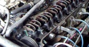 The gas distribution mechanism of the T-40 tractor engine needs to be checked from time to time and the valves adjusted as accurately as possible, which is usually performed not in a repair, but in a working order by the machine operator himself. According to the technical rules, such an adjustment should take place every 480 hours of tractor operation (that is, at least every 20 days).
The T-40 engine has 4 valves as standard - two exhaust and two intake valves for starting fresh air into the cylinders, exhausting exhaust gases and protecting the combustion chamber. For D-36, D-37 engines, they have plates of different diameters - exhaust pipes are 4 mm smaller. The valves are actuated by the lateral force of the rocker arms on their stems. It is precisely in debugging the gap between the strikers of the rocker arms and the valve stems, as well as in ensuring the tightest fit of the valves to the saddles, that the adjustment of this mechanism consists:
- If the gap between the valves and the rocker arm is too small, unwanted gas leakage may occur,
- If this distance is large, it can cause knocking and rapid wear of parts.
Valve adjustment must be carried out on a cold engine and in the same order in which it works: first the 1st valve, then the 3rd, 4th and 2nd.
In this case, the adjustment of each individual valve takes place in several successive stages:- On the drive pulley, the position of the piston of the first of the engine cylinders is set to the final compression position before the intake and exhaust valves close.
- The wedge of the rear cardan is removed. This can be done if you move the shaft with the steering wheel turned towards you, then the cardan is easily retracted to the side.
- The locknut at the rocker arm adjusting screw is loosened.
- The clearance is checked with a special feeler gauge. Ideally, with a cold engine, it should be exactly 0.3 mm.
- The gap is adjusted by changing the degree of screwing of the screw (tightening it more or loosening it).
- The value is again checked with a feeler gauge.
- With satisfactory control data, the lock nut is installed back and tightened.
After the actions taken and with moderate engine operation, the tightness of the valves can be maintained for a sufficient time for continuous operation without adjustment.
On the video, the t-40AM tractor in operation:such?))The T-140 tractor is designed for use with mounted, semi-mounted and trailed implements in the construction of industrial, hydraulic, road and other facilities with a large amount of earthworks. The productivity of the tractor compared to the S-80 (which at that time was like a standard) is 1.5 - 2.0 times higher.
The layout is made according to the scheme with the front engine and rear - transmission and driver's cab. Tractor frame - welded from two longitudinal spars and box-section crossbars, made of sheet structural steel 8 mm thick. The frame has four side brackets designed for additional vertical load on the tractor up to 20 tons for the installation of interchangeable attachments.
The tractor is equipped with an all-metal double cabin with heat and sound insulation, with all-round visibility.
The 6KDM-50T tractor engine is a six-cylinder, more powerful modification of the KDM-46. Parts such as pistons, liners, rings, camshafts. gears, regulator, nozzles, etc. are interchangeable for these engines. Power is increased by increasing the number of cylinders. On the 6KDM-50T engine, two air cleaners of a combined type with ejection dust extraction by exhaust gases are used. A reserve oil tank (25 l) of the lubrication system was installed.
The transmission has a device that allows you to reduce the speed of the tractor to 0.1 - 0.5 km / h. In this case, a creeper is installed on the rear wall of the transmission housing and the power from the engine is transmitted through the PTO and gearbox directly to the final drive gear, bypassing the gearbox.
Suspension of the tractor is torsion - balancing. The load is distributed on 12 road wheels (6 on each side), interlocked in pairs on a two-arm balancer into carriages that swing on the axles of one-arm balancers, which, in turn, are inserted into the suspension unit welded into the frame. For elastic suspension, lamellar torsion bars are used, located inside the pipe of a single-arm balancer, five pieces each.
Track rollers, support rollers and track idlers are made with a single spherical rim. The driving wheel has a lantern engagement with the caterpillar. The latter is made of large-linked, with cast tracks made of alloy steel.
Tractor control is pneumatic, with a follower for the clutch and brake control servo mechanism, as well as with a pneumatic crane for controlling attachments.
Technical characteristics of the tractor T-140Engine 6KDM-50T
Engine type diesel, water cooling
Pre-chamber mixing
Rated engine power, h.p. 140
Frequency of rotation of a cranked shaft at rated power, rpm 1000
The working volume of cylinders, l 20.28
Specific fuel consumption at rated power, g/e. hp-h 208
Cylinder order 1-5-3-6-2-4
Starting the engine with the P-46 starting engine
Dry engine weight, t 2.8
Single-wire electrical system (+ on the case)
Voltage, V 12
Pneumatic system compressor brand 200-3509015V
Operating pressure of the pneumatic system, atm 6 - 7
Hook power on stubble, h.p. 115
Traction range:
..forward travel 14400 - 2350
..reverse 11580 - 3960
Speed range, km/h:
..forward travel 2.38 - 10.9
..reverse 2.67 - 6.82
Specific pressure on soil, kgf/cm2:
..with a normal track width of 0.42
..with a swamp track width of 0.24
Tractor track, mm 2040
Tractor base, mm 2319
Ground clearance without ridge immersion, mm 500
Track width, mm
..normal 700
..swamp 900
Dry weight of the tractor, t 14.35
Weight in working order, t 15.0
Overall dimensions, L-W-H 5800 x 2740 x 2800If you take into account the overall dimensions of the tractor, then the oil will fit DOWN!!!
Tractor (novolat. tractor, "tractor") - a trackless vehicle used as a tractor. It features low speed and high traction. It is widely used in agriculture for plowing and moving non-self-propelled machines and implements. The tractor can be equipped with mounted and semi-mounted agricultural, construction or industrial equipment (for example, drilling equipment).
Important exclusivity is its parameters and favorable appearance. The outline of the tractor and the layout of the gearbox makes the transport useful at the fair.
The description of the base 40 is also detailed, which reflect all the features of this particular machine.
Release years:
T-40 - 1961-77,
T-40A - 1963-77,
T40-40AM - 1972-95 
Technical characteristics of tractors T-40 (T-40A)
Engine power, h.p. (kW) 40 (29.4)
Structural weight of the tractor T-40 (T-40A), kg 2370 (2570)
Number of forward/reverse gears 7/7
Range of forward and reverse speeds, km/h 1.6-26.7
Prevention and maintenance of the tractor T-150.
Tractor parts and assemblies are under the influence of large alternating loads, as well as thermal, physical and chemical processes. Under the influence of these loads and processes, parts wear out, fittings and interfaces change, the quality of oils and lubricants deteriorates, filter elements become clogged, initial adjustments are violated, fasteners are weakened, the specific consumption of fuel and oils increases, and tractor productivity decreases.
Timely and fully carried out maintenance and preventive maintenance ensure the restoration of the main technical characteristics. Only strict observance of operating recommendations excludes premature failure of the tractor. 
But the fact is that many farms do not have the appropriate maintenance of agricultural machinery, including the widespread T-150 tractors.
The most maintenance (TO) came down to was the replacement of oils, often without flushing and replacing filters. After all, TO is a complex of events. Providing high readiness of tractors to perform work, ensuring their performance during the established operating time.
Often there is a negligent attitude of machine operators to the engine cooling system. Is there water? No leak? At best, checks the tension of the water pump drive belt by eye. That's all service. But the technical and economic indicators of the tractor largely depend on the state of the engine cooling system.
It would seem, what does water have to do with fuel consumption, oils and engine wear? The presence of 1 mm of scale on the walls of the block increases the waste. Thermal conductivity of scale is 50…100 times less than metal. A layer of scale 3 mm thick increases the thermal resistance by 500 times. The tractor engine is overheating.
But it is known that scale accelerates the wear of parts of the piston group by 5-7 times, because with a large deposition of scale, the temperature of the liners and pistons rises from 120oC (at which they should work) to 200-350oC. At this temperature, high-temperature oil oxidation begins with the formation of resins and asphalts, which, when oxidized with oxygen, turn into carbenes and carboids, the oil loses its lubricating property, as a result of which the wear of parts not only of the piston group, but also of all other engine components is accelerated.
Accordingly, the conclusion suggests itself that it is necessary to operate in such a way that scale does not form in it. Where does she come from? The fact is that there are salts in dissolved form in water, which, when heated, settle on the walls in the form of scale. And the "harder" the water, the more salts it contains. 
So the conclusion suggests itself - it is necessary to use water in which there will be a minimum amount of salts. The best is distilled. If it is not available, you can use rain or snow water, which in their composition are close to distilled. You can do it even easier - pour water into the engine cooling system that was drained before repair. If only “hard” water is available, then it must be “softened” before pouring by adding 20 g of trisodium phosphate or 6–7 g of caustic soda and 10–20 g of washing soda per 10 liters of water.
In case of a difficult financial situation, you can use the old method: soak 2 kg of dry hay or 10 kg of any grass in hot water. Filter and add 15% of the resulting solution to the poured water.
Any operation of the tractor begins with refueling. Up to 80% of fuel equipment failures occur due to the use of low-quality fuel. Currently, fuels and lubricants (POL) are supplied to agriculture by all and sundry. Often no one is responsible for the quality of fuel and lubricants and no one monitors. Does the fuel comply with GOST in terms of sulfur content, impurities - no one knows.
Refueling with high-sulfur fuel accelerates the wear of the piston group by half. But no one will say what kind of fuel was brought to the farm. It would seem that what's the point that you know what kind of fuel is poured into the tank. But it turns out that the harmful effects can be greatly reduced by maintaining a temperature regime of at least 85 - 95oC. At lower temperatures, moisture condenses in the cylinders, which, when combined with sulfur dioxide, gives sulfurous acid, which contributes not only to increased piston wear, but also to the oxidation of the liners.
In addition, a fuel with a high sulfur content is needed more often than motor oil, since it loses its qualities.
Prolonged operation of the engine in idle mode (more than 5 minutes), as well as operation of a cold engine, contribute to the breakthrough of gases into the crankcase, oxidizing the oil, contributes to the deposition of carbon deposits on the pistons and coking of the piston rings.
But also work at high speeds without load destroys the engine by inertia forces even faster than by chemical reactions.
Also, for the engine, a sharp set of revolutions or sharp regassing is destructive, which many tractor drivers do when starting or stopping the engine. This is especially dangerous immediately after starting the engine, when the oil has not yet come to the rubbing parts in the required amount, and the gaps in the cold engine mates are increased.
If someone "revs" on a T-150 tractor with an engine equipped with a turbocharger, he punishes himself. After all, when the engine is running at maximum speed, the turbocharger shaft spins up to a frequency of 60-80 thousand rpm, its parts heat up.
If you immediately turn off the engine, then the pressure oil will stop flowing, and the turbocharger shaft will continue to rotate by inertia. The rest of the oil film burns out from the high temperature of the heated parts. Dry friction of the mating parts of the shaft and bushings leads to intense wear.
And it turns out that in the evening it "gasped", and in the morning the diesel engine either did not start at all, or did not develop power, or burned too much oil. Therefore, it should be remembered that before turning off the engine equipped with a turbocharger, it is necessary that it first run at idle for about 5 minutes, and then turn off the fuel supply by reducing the fuel supply.
Very often, insufficient attention is paid to the operation of nozzles. But poor atomization of one nozzle increases fuel consumption by 10 ... 20% and significantly accelerates engine wear as a whole. All burnt pistons are the result of an injector failure or the wrong brand of atomizer or other design features. And that is not all. There is such a concept in the operation of diesel engines as "soft", "hard" and "emergency" work.
"Soft" work is when the pressure on the piston increases by 3 - 5 kgf / cm2 for 1o of crankshaft rotation. This happens only when the fuel is used with a cetane number of 40 ... 50, an optimal injection angle for a given engine and a fuel injection pressure that differs by no more than 3 - 5% from the nominal value.
If at least one of the parameters does not correspond to the nominal value, the pressure on the piston increases to 6 - 8 kgf / cm2 per 1o of rotation, the engine runs hard and the engine, even a new one, does not work for more than a year.
During "emergency" operation, when the pressure rises to 8-10 kgf/cm2, i.e. when two or three parameters are not maintained, the engine wears out catastrophically quickly.
I would also like to dwell on the use of domestic and foreign oils in engines. The fact is that the additives used in domestic oils, and in foreign oils, often from different companies, are often not compatible with each other.
When we drain the oil from the engine, a certain amount of old oil remains in it. Even if you fill the engine with the same oil as the drained one, this oil will immediately lose up to 30 ... 40% of additives, which will be spent on eliminating contaminants left from the previous lubricant.
Therefore, in order to extend the life of the engine, it is necessary to flush it. Of course, now you will not find a washing machine anywhere. But you can pour a mixture of 50% industrial oil "I-12" or "I-20" into the engine, crank the engine with a launcher or starter for 3 - 5 minutes. After that, drain the oil and blow out the engine lubrication system with compressed air. 
And, if when replacing the same oils this condition is desirable, then when replacing domestic oils with foreign oils or foreign ones, but from another company, it is necessary. Otherwise, precipitation of additives, blockage of oil channels and emergency engine failure may occur.
Checking and adjusting valve clearance and decompression mechanism
To make this work, you need to do the following.
1. Remove the block head cover, carefully wipe the outer parts of the timing mechanism, pressing the valve glass with your hand, check if the valve is stuck in the sleeve.
2. Tighten the fastening of the head of the block and the racks of the rocker rollers.
3. Turn the crankshaft so that there is a compression stroke in the first cylinder (both valves are closed), and the mounting pin (probe), inserted into the hole in the rear beam with an uncut end, enters the hole at the end of the flywheel (20 ° to TDC). The desired position of the shaft can be found with sufficient accuracy without using the adjusting pin. To do this, turning the shaft manually, it is necessary to follow the movement of the rods. After the exhaust valve stem, and after it the intake valve, rises and falls in succession, the shaft should be rotated an additional 1/4 - 1/2 turn.
4. Check if the decompression mechanism is turned off (the bolts must be in a horizontal position).
5. Check the gap between the valve glass and the rocker arm with a feeler gauge. On a warm engine, the normal clearance should be 0.25 mm, on a cold one - 0.30 mm. In case of deviations from the norm, the gap is set with an adjusting screw (Fig. 21, a).
Adjustment of valves and decompression mechanism of the D-Z6 engine 
Rice. 21. Adjustment of valves (a) and decompression mechanism (b) of the D-Z6 engine
6. Engage the decompression mechanism (bolts in vertical position). Unscrew the decompression mechanism bolt, and then turn it so that the rocker touches the valve spring cup, then turn it another 1 turn. In this case, the valve will open by 1 - 1.25 mm (Fig. 21.6). A larger opening of the valves is unacceptable, since the gap between the piston crown and the plane of the head when the piston is at TDC is only 1.8 mm.
7. Turn the crankshaft half a turn and check, and if necessary, adjust the valves of the third, and then the fourth and second cylinders.
Checking and adjusting valves for D-24 and D-14 engines is carried out in a similar way, you should only additionally check the presence of safety rings on the valve stems.
sale of tractors t 40
In 1961, the Lipetsk Tractor Plant mastered the production of a wheeled tractor under the designation T-40.
The successful design of the T-40, the good technical parameters of this universal row-crop tractor helped to gain popularity, as evidenced by being on the conveyor until 1995. The advantages and disadvantages of the agricultural unit model include:
- front-engine layout;
- the successful design of the transmission and gearbox on the T-40;
- economy of operation;
- reliability;
- maintainability.
These advantages of the T-40 helped develop modifications that are in demand in industry and in other industries. Among the main ones:
- 40AM - all-wheel drive version;
- 41AN - a variant with a reduced clearance for agricultural work on land slopes;
- 50A - loader with bucket;
- - caterpillar version of the tractor;
- 40AP - modification for use in the housing and communal sector.
Technical parameters T-40
 The versatility in use and, as a result, the popularity of the T-40 provided technical characteristics, while the speed parameters coincide with:
- Class - 0.9.
- Load capacity - 0.85 tons.
- Drive - front (4x2).
- Engine - D-144:
- Type - diesel.
- The number of cylinders is 4.
- The volume of cylinders is 4.20 liters.
- Cooling - air.
- Power - 50.50 liters. With.
- Dimensions:
- Length - 3.66 m.
- Height - 2.38 m.
- Width - 1.63 m.
- Wheelbase - 2.15 m.
- Transmission:
- Mechanical.
- Shift scheme - 8 forward and reverse gears.
- Clutch - friction single-plate clutch.
- Maximum speed (smallest):
- forward travel - 26.72 (1.63) km / h.
- reverse gear - 5.35 (1.96) km / h.
- Are common:
- Weight - 2.37 tons.
- The volume of tanks is 74.0 liters.
- Fuel consumption - 185 g / kW * h.
- Clearance - 0.65 m.
Gearbox device
 In the design of the T-40 tractor, a gearbox is designed to change the direction of movement, select the speed and perform operations. The design of the box is represented by the following elements:
- creeper;
- reverse mechanism with bevel gear;
- blocking device;
- special shafts, gears with a switching mechanism;
- final drive with differential lock device.
- Creeper. The device is intended, instead of a transfer case, to form an additional number of reduced speeds for the T-40, as well as to increase the amount of aggregated equipment when performing various work. The design of the creeper is an enlarged gear train with external and internal gearing, which, when interacting with each other, form a reduced gear ratio (2.75), which is transmitted to the T-40 driven shaft.
- Reverse. The reverse mechanism with a special gear is designed to receive an additional number of speeds in the box for reversing. By design, it is a gearbox, the principle of which is to change the gears of engagement in a bevel gear, in which the direction and speed of the driven shaft change.
- Special shafts and gears, switching mechanism. Designed to obtain the speed of movement or change of direction. The box distinguishes between the input and drive shafts, as well as gears. The required gear is obtained by moving a given movable gear to engage it with a fixed gear located on another shaft. The shifting mechanism is designed with the help of special shifting shafts, on which the fork is mounted. The shafts are moved using a shift lever, while the forks shift the moving gears.
- Gear blocking device. The device is designed to prevent incomplete gear engagement in the box, as well as spontaneous separation. The main element is a special shaft for blocking and clamps. When the required gear is engaged, the blocking shaft moves in parallel to the required gear, and when the teeth match, the clamps secure the connection.
- Main gear with differential lock. It is used to transmit torque from the engine to the drive wheels, consists of two spur gears. The differential lock device is designed to obtain the same rotation speed of the right and left tractor wheels.
Service
 For reliable long-term operation and a reduction in the number of gearbox repairs of the T-40 tractor, it is necessary to carry out maintenance regulated by the manufacturer.
An important operation is to check the quality, level, and service life of the lubricant in the box body.
High-quality gear oil will protect gears and shafts from premature wear and corrosion.
It is necessary to use a lubricant with a specified temperature regime for periods of operation (summer, winter, all-weather).
The oil level check interval is performed every 240 hours of operation. Check the level using the control plug, which is located on the gearbox housing.
In the case of a reduced level, fill in the oil to the norm through the control hole. It is strongly not recommended to fill the transmission fluid above the reference mark, as this will lead to the creation of an increased density of the oil film on the gear teeth, which causes deformation.
When changing the transmission fluid, every 960 hours of operation, it is required to flush the elements and components of the box. To do this, the oil is drained from a hot engine, which allows you to clean the box from deposits.
Also, in the T-40 gearbox, the amount of engagement of the gear teeth is not regulated until a complete loss of performance.
Performing such simple operations will allow high-quality maintenance of the gearbox, increase the period of operation of the multifunctional T-40.