I needed to make a speed controller for the propeller. To blow away the smoke from the soldering iron and ventilate the face. Well, just for fun, pack everything into a minimum price. The easiest way to regulate a low-power DC motor, of course, is with a variable resistor, but to find a motor for such a small nominal value, and even the required power, it takes a lot of effort, and it obviously won’t cost ten rubles. Therefore, our choice is PWM + MOSFET.
I took the key IRF630. Why this one MOSFET? Yes, I just got about ten of them from somewhere. So I use it, so I can install something smaller and low-power. Because the current here is unlikely to be more than an ampere, but IRF630 capable of pulling through itself under 9A. But it will be possible to make a whole cascade of fans by connecting them to one fan - enough power :)
Now it's time to think about what we will do PWM. The thought immediately suggests itself - a microcontroller. Take some Tiny12 and do it on it. I threw this thought away instantly.
- I feel bad about spending such a valuable and expensive part on some kind of fan. I'll find a more interesting task for the microcontroller
- Writing more software for this is doubly frustrating.
- The supply voltage there is 12 volts, lowering it to power the MK to 5 volts is generally lazy
- IRF630 will not open from 5 volts, so you would also have to install a transistor here so that it supplies a high potential to the field gate. Fuck it.
Op amps can be discarded outright. The fact is that for general-purpose op-amps, already after 8-10 kHz, as a rule, output voltage limit it begins to collapse sharply, and we need to jerk the fieldman. Moreover, at a supersonic frequency, so as not to squeak.
Op-amps without such a drawback cost so much that with this money you can buy a dozen of the coolest microcontrollers. Into the furnace!
What remains are comparators; they do not have the ability of an op-amp to smoothly change the output voltage; they can only compare two voltages and close the output transistor based on the results of the comparison, but they do it quickly and without blocking the characteristics. I rummaged through the bottom of the barrel and couldn’t find any comparators. Ambush! More precisely it was LM339, but it was in a large case, and religion does not allow me to solder a microcircuit for more than 8 legs for such a simple task. It was also a shame to drag myself to the storehouse. What to do?
And then I remembered such a wonderful thing as analog timer - NE555. It is a kind of generator where you can set the frequency, as well as the pulse and pause duration, using a combination of resistors and a capacitor. How much different crap has been done on this timer over its more than thirty-year history... Until now, this microcircuit, despite its venerable age, is printed in millions of copies and is available in almost every warehouse for a price of a few rubles. For example, in our country it costs about 5 rubles. I rummaged through the bottom of the barrel and found a couple of pieces. ABOUT! Let's stir things up right now.
 |
How it works
If you don’t delve deeply into the structure of the 555 timer, it’s not difficult. Roughly speaking, the timer monitors the voltage on capacitor C1, which it removes from the output THR(THRESHOLD - threshold). As soon as it reaches the maximum (the capacitor is charged), the internal transistor opens. Which closes the output DIS(DISCHARGE - discharge) to ground. At the same time, at the exit OUT a logical zero appears. The capacitor begins to discharge through DIS and when the voltage on it becomes zero (full discharge), the system will switch to the opposite state - at output 1, the transistor is closed. The capacitor begins to charge again and everything repeats again.
The charge of capacitor C1 follows the path: “ R4->upper shoulder R1 ->D2“, and the discharge along the way: D1 -> lower shoulder R1 -> DIS. When we turn the variable resistor R1, we change the ratio of the resistances of the upper and lower arms. Which, accordingly, changes the ratio of the pulse length to the pause.
The frequency is set mainly by capacitor C1 and also depends slightly on the value of resistance R1.
Resistor R3 ensures that the output is pulled to a high level - so there is an open-collector output. Which is not able to independently set a high level.
You can install any diodes, the conductors are approximately the same value, deviations within one order of magnitude do not particularly affect the quality of work. At 4.7 nanofarads set in C1, for example, the frequency drops to 18 kHz, but it is almost inaudible, apparently my hearing is no longer perfect :(
I dug into the bins, which itself calculates the operating parameters of the NE555 timer and assembled a circuit from there, for astable mode with a fill factor of less than 50%, and screwed in a variable resistor instead of R1 and R2, with which I changed the duty cycle of the output signal. You just need to pay attention to the fact that the DIS output (DISCHARGE) is via the internal timer key connected to ground, so it could not be connected directly to the potentiometer, because when twisting the regulator to its extreme position, this pin would land on Vcc. And when the transistor opens, there will be a natural short circuit and the timer with a beautiful zilch will emit magic smoke, on which, as you know, all electronics work. As soon as the smoke leaves the chip, it stops working. That's it. Therefore, we take and add another resistor for one kilo-ohm. It won’t make a difference in regulation, but it will protect against burnout.
No sooner said than done. I etched the board and soldered the components:
Everything is simple from below.
Here I am attaching a signet, in the native Sprint Layout -
And this is the voltage on the engine. A small transition process is visible. You need to place the conduit in parallel at half a microfarad and it will smooth it out.
As you can see, the frequency floats - this is understandable, because in our case the operating frequency depends on the resistors and capacitor, and since they change, the frequency floats away, but this does not matter. Throughout the entire control range, it never enters the audible range. And the entire structure cost 35 rubles, not counting the body. So - Profit!
The simplest generator of pulse-width signals.
The main purpose of the PWM Generator program is to generate pulse width modulation signals in real time. These tones are generated based on specified values of frequency (in Hertz), duty cycle - the ratio of time between low and high states of the signal (in percent), and amplitude - the level of the digital signal (in dBFS). All of the above parameters can be instantly changed during operation. The maximum possible signal level generated is 0 dBFS, and the highest frequency is half the sampling frequency. A whole menu of output characteristics is provided to configure the sound generation to the optimal level of quality. There is the ability to change the number and size of internal data buffers, sampling frequency and quantization.
The software can be used to create control tones for various electrical and electromechanical devices. In particular, the resulting PWM signal, taken from the output of the sound card of a personal computer and passed through a standard audio amplifier, is used to control motors, fans, and lighting devices.
PWM Generator supports working with several sound cards, and you can select the one that will be used to output the desired signal (by default, the program works with the output device specified in the Windows Control Panel). It is worth noting that the working PWM signal can be saved as a WAV file and later listened to using standard software. And if you regularly use certain tones, the PWM signal generator makes it possible to save (and load) them as presets. Additionally, several presets come with the app.
PWM Generator supports the option of synchronizing all running instances of the program, allowing you to generate several tones at once. It should be noted that the software can run in the background, allowing users to switch attention to other applications. In addition, PWM Generator can be controlled using script commands, as well as through Windows Messaging systems.
The authors report that the faster the workstation, the higher the audio quality and responsiveness of the controls when playing tones.
The application in question was written by employees of the German company Esser Audio. This organization is engaged in the creation and distribution of software products (, etc.), intended mainly for testing and testing audio equipment. Programs from Esser Audio are distinguished by good functionality and an extremely simple interface.
The PWM Generator program is shareware, the trial version allows you to freely launch and test the application during the first thirty days. The cost of the program for countries outside the European Union is 14 euros, for those within the European Union - 16.66 euros (due to the addition of sales tax). A discount is provided when purchasing multiple licenses.
The application is distributed in English and German. The help file contains a detailed description of all the software's capabilities, and an online help forum has been created to provide additional support to users of the software package. There is no Russian version of PWM Generator yet.
The latest version of the software works on any computer with a 32- or 64-bit Microsoft Windows operating system (9x, NT, 2000, 2003, XP, Vista, 7, 8) and a sound card.
Program distribution: shareware 14 euros. There is a trial version (30 days)
Photo of the generator.

What can this generator do? Let's take a look at the parameters.
- Operating voltage: 3.3 - 30V;
- Generation frequency: 1Hz - 150KHz;
- Frequency generation accuracy: 2%;
- Load power: 5…30mA;
- The amplitude of the output signal is equal to the supply voltage;
- Ambient temperature: -20 … +70 °C.

Only 2 numbers of 3 digits each can be displayed. The bottom line displays the PWM duty cycle as a percentage, and the top line displays the frequency. The frequency is displayed according to the following rules:
- XXX, 1Hz step, range 1 – 999Hz;
- X.XX, step in 0.01 kHz, in the range 1.00 - 9.99 kHz;
- XX.X, step in 0.1 kHz; in the range 10.0 - 99.9 kHz;
- X.X.X, 1 kHz step; in the range 100 - 150 kHz.
The display is controlled by the HT1621B chip, the display is universal, it contains the symbols necessary to build a thermometer, hygrometer, voltmeter, ammeter and wattmeter, but in our case they are not used. The display has a bright blue backlight. By the way, I note that the display on my generator turned out to be shabby, as if it had been removed from somewhere.

The main chip of the generator is the STM8S003F3P6 microcontroller. And since this microcontroller has EEPROM memory, the settings are saved when turned off.
The generator can be controlled in two ways: buttons and via UART. Everything is clear with the buttons, one pair of buttons controls the frequency, the second the duty cycle. But with UART everything is much more interesting. Data exchange must occur with the following parameters:
- 9600 bps Data bits: 8
- Stop bit: 1
- Check digit: none
- Flow control: none
In order to set the generation frequency, you need to send the frequency as it is displayed on the display by adding the letter F in front of the frequency value. For example, to set the frequency to 100 Hz you need to send F100, for 105 kHz - F1.0.5, for 10.5 kHz - F10 .5 and so on.
To set the duty cycle, you need to send a three-digit duty cycle number by adding the letter D in front of it. For example, D050, D100, D001.
If a correct command is sent, the generator will respond DOWN, if an incorrect one - FALL. But there is one BUT, I was never able to configure work with the generator via UART.
I decided to test the generator using a logic analyzer. This is what happened.
Frequency 1 Hz, duty cycle 1%. As we can see, the error is still small.

Frequency 1 Hz, duty cycle 50%.

Frequency 1 Hz, duty cycle 99%.

Frequency 1 kHz, duty cycle 1%.

Frequency 1 kHz, duty cycle 50%.

Frequency 1 kHz, duty cycle 99%. Here we see that with the duty cycle set to 99%, the fill is actually 100%.

Frequency 1 kHz, duty cycle 91%. I began to reduce the duty cycle, and up to 92% the filling was 100%, and only at 91% the situation improved.

Frequency 50 kHz, duty cycle 1%. As you can see, it’s only 0.2% instead of 1%.

Frequency 50 kHz, duty cycle 50%. Here it differs by 1%.

Frequency 50 kHz, duty cycle 99%. And here again the deviation is -1%.

Frequency 100 kHz, duty cycle 1%. But there’s nothing here yet.

Frequency 100 kHz, duty cycle 2%. And at 2% the signal appears, but in fact the filling is 0.4%.

Frequency 100 kHz, duty cycle 50%. The deviation is almost -2%.

Frequency 100 kHz, duty cycle 99%. And here it’s almost -1%.

Frequency 150 kHz, duty cycle 1%. No signal again.

Frequency 150 Hz, duty cycle 3%. And the signal appears only at 3%, but the filling is 0.6%.

Frequency 150 kHz, duty cycle 50%. But in fact, the filling is 46.5%, a difference of -3.5%.

Frequency 150 kHz, duty cycle 99%. And there is an error, but only 1.5%.

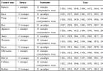
The sample is quite rough, but the research is not over yet. I decided to measure the duty cycle at different fill rates (5% steps) and at different frequencies (25000 Hz steps) and put them in a table.
Generator circuit and adjustable duty cycle, controlled by input voltage. Source of pulse signal with variable duty cycle. Pulse duration limitation (10+)
Duty factor of the pulse signal. Duty Cycle - Generator
Duty ratio adjustment
To obtain a signal with a controlled duty cycle, it is convenient to use PWM controllers. These specialized chips are specifically designed to generate signals with a duty cycle that depends on external conditions.
For example, let's look at circuits based on an integrated PWM controller 1156EU3 or UC3823.
Here is a selection of materials: Resistor R1- 10 kOhm, trimmer. It is used to adjust the initial signal level at which pulses of minimum duration will appear. Resistor R2- 100 kOhm Resistor R3- 500 kOhm, trimmer. It regulates the sensitivity, that is, increasing this resistor causes a signal of a given amplitude to result in a larger change in the duty cycle. Resistor R4, Capacitor C1- set the frequency of the output signal. Formula for calculating the frequency depending on the parameters of these parts. Resistor R5- 100 kOhm, trimmer. It regulates the maximum possible fill factor, or in circuit (A3), simply the fill factor. Capacitor C1- 0.1 µF. A finished device illustrating duty cycle control - A simulator for relieving eye fatigue and spasm of accommodation. Limiting the maximum duty cycleIn many cases it is useful to limit the maximum duty cycle. It may be necessary to ensure that, regardless of the control signal, the duty cycle does not exceed a certain specified value. This is necessary, for example, in boosting, inverting, flyback, forward or push-pull power supply topologies so that the magnetic circuit of the inductor or transformer between pulses has time to be reliably demagnetized.
In the circuit, all pins and connections that are not relevant to our duty cycle limitation task have been removed. For example, the 1156EU3 or UC3823 microcircuit was selected. Without changes, the described approach can be used for the 1156EU2 or UC3825 chip. For other PWM microcircuits, you may need to select the part ratings and take into account the pinout of these microcircuits. The operating principle of the circuit is as follows. Leg 8 is responsible for a soft start. A current of 1 μA is supplied to it inside the microcircuit. This current charges the external capacitor. As the voltage across the capacitor increases, the maximum possible duty cycle increases. This ensures a gradual increase in pulse width during startup. This is necessary because the output capacitor is discharged when turned on, and if you rely on feedback, the pulse duration will be maximum until this capacitor is charged to operating voltage. This is undesirable as it results in overload when the device is turned on. The trimmer resistor and diode limit the maximum possible voltage to which the capacitor can be charged, and therefore the maximum possible duty cycle. At the same time, the soft start function is completely preserved. The pulse width gradually increases from zero to the set value as the capacitor is charged. Further, the increase in the fill factor stops. Diode- any low-power, for example, KD510 Trimmer resistor- 100 kOhm Unfortunately, errors are periodically found in articles; they are corrected, articles are supplemented, developed, and new ones are prepared. |

When working with many different technologies, the question is often: how to manage the power that is available? What to do if it needs to be lowered or raised? The answer to these questions is a PWM regulator. What is he? Where is it used? And how to assemble such a device yourself?
What is pulse width modulation?
Without clarifying the meaning of this term, it makes no sense to continue. So, pulse-width modulation is the process of controlling the power that is supplied to the load, carried out by modifying the duty cycle of the pulses, which is done at a constant frequency. There are several types of pulse width modulation:
1. Analog.
2. Digital.
3. Binary (two-level).
4. Trinity (three-level).
What is a PWM regulator?

Now that we know what pulse width modulation is, we can talk about the main topic of the article. A PWM regulator is used to regulate the supply voltage and to prevent powerful inertial loads in automobiles and motorcycles. This may sound complicated and is best explained with an example. Let’s say you need to make the interior lighting lamps change their brightness not immediately, but gradually. The same applies to side lights, car headlights or fans. This desire can be realized by installing a transistor voltage regulator (parametric or compensation). But with a large current, it will generate extremely high power and will require the installation of additional large radiators or an addition in the form of a forced cooling system using a small fan removed from the computer device. As you can see, this path entails many consequences that will need to be overcome.
The real salvation from this situation was the PWM regulator, which operates on powerful field-effect power transistors. They can switch high currents (up to 160 Amps) with only 12-15V gate voltage. It should be noted that the resistance of an open transistor is quite low, and thanks to this, the level of power dissipation can be significantly reduced. To create your own PWM regulator, you will need a control circuit that can provide a voltage difference between the source and gate within the range of 12-15V. If this cannot be achieved, the channel resistance will greatly increase and the power dissipation will increase significantly. And this, in turn, can cause the transistor to overheat and fail.
A whole range of microcircuits for PWM regulators are produced that can withstand an increase in input voltage to a level of 25-30V, despite the fact that the power supply will be only 7-14V. This will allow the output transistor to be turned on in the circuit along with the common drain. This, in turn, is necessary to connect a load with a common minus. Examples include the following samples: L9610, L9611, U6080B ... U6084B. Most loads do not draw more than 10 amps of current, so they cannot cause voltage sags. And as a result, you can use simple circuits without modification in the form of an additional unit that will increase the voltage. And it is precisely these samples of PWM regulators that will be discussed in the article. They can be built on the basis of an asymmetrical or standby multivibrator. It’s worth talking about the PWM engine speed controller. More on this later.
Scheme No. 1

This PWM controller circuit was assembled using CMOS chip inverters. It is a rectangular pulse generator that operates on 2 logic elements. Thanks to the diodes, the time constant of discharge and charge of the frequency-setting capacitor changes separately here. This allows you to change the duty cycle of the output pulses, and as a result, the value of the effective voltage that is present at the load. In this circuit, it is possible to use any inverting CMOS elements, as well as NOR and AND. Examples include K176PU2, K561LN1, K561LA7, K561LE5. You can use other types, but before that you will have to think carefully about how to correctly group their inputs so that they can perform the assigned functionality. The advantages of the scheme are the accessibility and simplicity of the elements. Disadvantages are the difficulty (almost impossibility) of modification and imperfection regarding changing the output voltage range.
Scheme No. 2

It has better characteristics than the first sample, but is more difficult to implement. Can regulate the effective load voltage in the range of 0-12V, to which it changes from an initial value of 8-12V. The maximum current depends on the type of field-effect transistor and can reach significant values. Given that the output voltage is proportional to the control input, this circuit can be used as part of a control system (to maintain the temperature level).
Reasons for the spread
What attracts car enthusiasts to a PWM controller? It should be noted that there is a desire to increase efficiency when constructing secondary ones for electronic equipment. Thanks to this property, this technology can also be found in the manufacture of computer monitors, displays in phones, laptops, tablets and similar equipment, and not just in cars. It should also be noted that this technology is significantly inexpensive when used. Also, if you decide not to buy, but to assemble a PWM controller yourself, you can save money when improving your own car.
Conclusion

Well, you now know what a PWM power regulator is, how it works, and you can even assemble similar devices yourself. Therefore, if you want to experiment with the capabilities of your car, there is only one thing to say about this - do it. Moreover, you can not only use the diagrams presented here, but also significantly modify them if you have the appropriate knowledge and experience. But even if everything doesn’t work out the first time, you can gain a very valuable thing - experience. Who knows where it might come in handy next and how important its presence will be.