In one of the previous articles we discussed the main aspects related to working with, so today we will continue this topic. Everything we discussed earlier concerned, first of all, fixed resistors, the resistance of which is a constant value. But this is not the only existing type of resistor, so in this article we will pay attention to elements that have variable resistance.
So, what is the difference between a variable resistor and a constant one? Actually, the answer here follows directly from the name of these elements :) The resistance value of a variable resistor, unlike a constant one, can be changed. How? And that’s exactly what we’ll find out! First let's look at the conditional variable resistor circuit:

It can be immediately noted that here, unlike resistors with a constant resistance, there are three terminals, not two. Now let’s figure out why they are needed and how it all works :)
So, the main part of a variable resistor is a resistive layer that has a certain resistance. Points 1 and 3 in the figure are the ends of the resistive layer. Another important part of the resistor is the slider, which can change its position (it can take any intermediate position between points 1 and 3, for example, it can end up at point 2 as in the diagram). Thus, in the end we get the following. The resistance between the left and central terminals of the resistor will be equal to the resistance of section 1-2 of the resistive layer. Similarly, the resistance between the central and right terminals will be numerically equal to the resistance of section 2-3 of the resistive layer. It turns out that by moving the slider we can get any resistance value from zero to . A is nothing more than the total resistance of the resistive layer.
Structurally, variable resistors are rotary, that is, to change the position of the slider you need to turn a special knob (this design is suitable for the resistor shown in our diagram). Also, the resistive layer can be made in the form of a straight line, accordingly, the slider will move straight. Such devices are called sliding or sliding variable resistors. Rotary resistors are very common in audio equipment, where they are used to adjust volume/bass, etc. Here's what they look like:

A slider type variable resistor looks a little different:
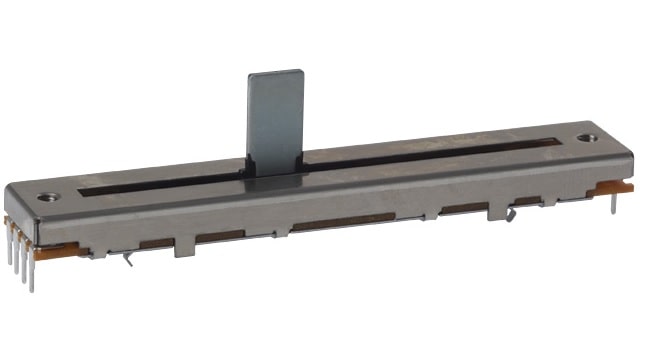
Often when using rotary resistors, switch resistors are used as volume controls. Surely you have come across such a regulator more than once - for example, on radios. If the resistor is in its extreme position (minimum volume/device is turned off), then if you start to rotate it, you will hear a noticeable click, after which the receiver will turn on. And with further rotation the volume will increase. Similarly, when decreasing the volume - when approaching the extreme position, there will be a click again, after which the device will turn off. A click in this case indicates that the receiver's power has been turned on/off. Such a resistor looks like this:

As you can see, there are two additional pins here. They are precisely connected to the power circuit in such a way that when the slider rotates, the power circuit opens and closes.
There is another large class of resistors that have a variable resistance that can be changed mechanically - these are trimming resistors. Let's spend a little time on them too :)
Trimmer resistors.
Just to begin with, let’s clarify the terminology... Essentially trim resistor is variable, because its resistance can be changed, but let's agree that when discussing trimming resistors, by variable resistors we will mean those that we have already discussed in this article (rotary, slider, etc.). This will simplify the presentation, since we will be contrasting these types of resistors with each other. And, by the way, in the literature, trimming resistors and variables are often understood as different circuit elements, although, strictly speaking, any trim resistor is also variable due to the fact that its resistance can be changed.
So, the difference between trimming resistors and the variables that we have already discussed, first of all, lies in the number of cycles of moving the slider. If for variables this number can be 50,000 or even 100,000 (that is, the volume knob can be turned almost as much as you like 😉), then for trimming resistors this value is much less. Therefore, trimming resistors are most often used directly on the board, where their resistance changes only once, when setting up the device, and during operation the resistance value does not change. Externally, the tuning resistor looks completely different from the mentioned variables:

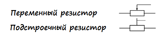
The designation of variable resistors is slightly different from the designation of constant ones:
Actually, we have discussed all the main points regarding variables and trimming resistors, but there is one more very important point that cannot be ignored.
Often in the literature or in various articles you can come across the terms potentiometer and rheostat. In some sources this is what variable resistors are called, in others these terms may have some other meaning. In fact, there is only one correct interpretation of the terms potentiometer and rheostat. If all the terms that we have already mentioned in this article related, first of all, to the design of variable resistors, then a potentiometer and a rheostat are different circuits for connecting (!!!) variable resistors. That is, for example, a rotary variable resistor can act both as a potentiometer and as a rheostat - it all depends on the connection circuit. Let's start with the rheostat.
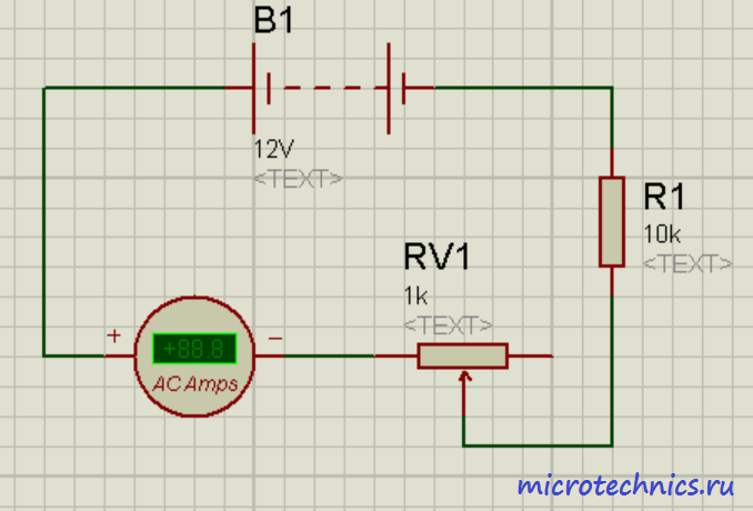
(a variable resistor connected in a rheostat circuit) is mainly used to regulate the current. If we connect an ammeter in series with the rheostat, then when we move the slider we will see a changing current value. The resistor in this circuit plays the role of a load, the current through which we are going to regulate with a variable resistor. Let the maximum resistance of the rheostat be equal to , then, according to Ohm’s law, the maximum current through the load will be equal to:
Here we took into account that the current will be maximum at a minimum value of resistance in the circuit, that is, when the slider is in the extreme left position. The minimum current will be equal to:

So it turns out that the rheostat acts as a regulator of the current flowing through the load.
There is one problem with this circuit - if contact is lost between the slider and the resistive layer, the circuit will be open and current will stop flowing through it. You can solve this problem as follows:

The difference from the previous diagram is that points 1 and 2 are additionally connected. What does this give in normal operation? Nothing, no changes :) Since there is non-zero resistance between the resistor slider and point 1, all the current will flow directly to the slider, as in the absence of contact between points 1 and 2. But what happens if contact between the slider and the resistive layer is lost? And this situation is absolutely identical to the absence of a direct connection of the slider to point 2. Then the current will flow through the rheostat (from point 1 to point 3), and its value will be equal to:
That is, if contact is lost in this circuit, there will only be a decrease in the current strength, and not a complete break in the circuit as in the previous case.
WITH rheostat We figured it out, let's look at a variable resistor connected according to the potentiometer circuit.

Don't miss the article about measuring instruments in electrical circuits -
Unlike a rheostat, it is used to regulate voltage. It is for this reason that in our diagram you see two voltmeters :) The current flowing through the potentiometer, from point 3 to point 1, remains unchanged when moving the slider, but the resistance value between points 2-3 and 2-1 changes. And since voltage is directly proportional to current and resistance, it will change. When moving the slider down, the resistance of 2-1 will decrease, and accordingly, the readings of voltmeter 2 will also decrease. With this movement of the slider (down), the resistance of section 2-3 will increase, and with it the voltage on voltmeter 1. In this case, the total readings of the voltmeters will be will be equal to the voltage of the power source, that is, 12 V. In the uppermost position on voltmeter 1 there will be 0 V, and on voltmeter 2 - 12 V. In the figure, the slider is located in the middle position, and the readings of the voltmeters, which is absolutely logical, are equal :)
This is where we finish looking at variable resistors, in the next article we will talk about possible connections between resistors, thank you for your attention, I will be glad to see you on our website! 🙂
Resistors include passive elements of electrical circuits. These elements are used to linearly convert current to voltage or vice versa. When converting voltage, current may be limited or electrical energy may be absorbed. Initially, these elements were called resistances, since it is this value that is decisive in their use. Later, in order not to confuse the basic physical concept and the designation of radio components, they began to use the name resistor.
Variable resistors differ from others in that they are capable of changing resistance. There are 2 main types of variable resistors:
- potentiometers that convert voltage;
- rheostats that regulate current.
Resistors allow you to change the sound volume and adjust circuit parameters. These elements are used to create sensors for various purposes, alarm systems and automatic switching on of equipment. Variable resistors are necessary for adjusting the speed of motors, photo relays, converters for video and audio equipment. If the task is to debug the equipment, then trimming resistors will be required.
Potentiometers
The potentiometer differs from other types of resistance in that it has three terminals:
- 2 permanent, or extreme;
- 1 movable, or middle.
The first two terminals are located at the edges of the resistive element and are connected to its ends. The middle output is combined with a movable slider, through which movement occurs along the resistive part. Due to this movement, the resistance value at the ends of the resistive element changes.
All variants of variable resistors are divided into wire and non-wire, this depends on the design of the element.

To create a non-wire variable resistor, rectangular or horseshoe-shaped plates from insulate are used, on the surface of which a special layer is applied that has a given resistance. Typically the layer is a carbon film. Less commonly used in design:
- microcomposite layers of metals, their oxides and dielectrics;
- heterogeneous systems of several elements, including 1 conductive element;
- semiconductor materials.
Attention! When using resistors with carbon film in the power circuit, it is important to prevent the element from overheating, otherwise sudden voltage drops may occur during the adjustment process.
When using a horseshoe-shaped element, the slider moves in a circle with a rotation angle of up to 2700C. Such potentiometers have a round shape. The rectangular resistive element has a translational slider movement, and the potentiometer is made in the form of a prism.
Wire options are built on the basis of high-resistance wire. This wire is wound around a ring-shaped contact. During operation, the contact moves along this ring. In order to ensure a strong connection to the contact, the track is additionally polished.

The material used depends on the accuracy of the potentiometer. Of particular importance is the diameter of the wire, which is selected based on the current density. The wire must have high resistivity. In production, nichrome, manganin, constatin and special alloys of noble metals, which have low oxidation and increased wear resistance, are used for winding.
In high-precision instruments, ready-made rings are used where the winding is placed. For such winding, special high-precision equipment is required. The frame is made of ceramics, metal or plastic.
If the accuracy of the device is 10-15 percent, then a plate is used, it is rolled into a ring after winding. Aluminum, brass or insulating materials, for example, fiberglass, textolin, getinax, are used as a frame.
Note! The first sign of resistor failure may be a crackling or noise when turning the knob to adjust the volume. This defect occurs as a result of wear of the resistive layer, and, therefore, loose contact.
Main characteristics
Among the parameters on which the operation of a variable resistor depends, not only the total and minimum resistance, but also other data are of great importance:
- functional characteristics;
- power dissipation;
- wear resistance;
- the existing degree of rotation noise;
- dependence on environmental conditions;
- sizes.
The resistance that occurs between the fixed terminals is called total.
In most cases, the nominal resistance is indicated on the housing and is measured in kilo- and mega-ohms. This value can fluctuate within 30 percent.
The dependence according to which the resistance changes when the moving contact moves from one extreme terminal to the other is called a functional characteristic. According to this characteristic, variable resistors are divided into 2 types:
- Linear, where the value of the resistance level is transformed in proportion to the movement of the contact;
- Nonlinear, in which the resistance level changes according to certain laws.

The figure shows different types of dependencies. For linear variable resistors, the dependence is shown in graph A, for nonlinear ones that work:
- according to the logarithmic law - on curve B;
- according to the exponential (inverse logarithmic) law - on graph B.
Also, nonlinear potentiometers can change resistance, as shown in graphs I and E.
All curves are plotted based on the readings of the total and current angle of rotation of the moving part - αn and α from the total Rn and current R resistance. For computer technology and automatic devices, the resistance level can vary in cosine or sine amplitudes.
In order to create wirewound resistors with the required functional characteristics, use a frame of different heights or change the distance in steps between turns of the winding. For the same purposes, in non-wire potentiometers the composition or thickness of the resistive film is changed.
Basic designations
In diagrams of current-carrying circuits, a variable resistor is designated as a rectangle and an arrow, which is directed to the center of the housing. This arrow shows the middle or moving control output.
Sometimes a circuit requires not smooth, but stepped switching. To do this, use a circuit consisting of several fixed resistors. These resistances are turned on depending on the position of the regulator knob. Then the step switching sign is added to the designation, the number on top indicates the number of switch stages.
For gradual volume control, dual potentiometers are integrated into the high-precision equipment. Here, the resistance value of each resistor changes with the movement of one regulator. This mechanism is indicated by a dotted line or double line. If in the diagram the variable resistors are located far from each other, then the connection is simply highlighted with a dotted line on the arrow.
Some dual variants can be controlled independently of each other. In such circuits, the axis of one potentiometer is placed inside another. In this case, the dual connection designation is not used, and the resistor itself is marked according to its positional designation.
The variable resistor can be equipped with a switch that supplies power to the entire circuit. In this case, the switch handle is combined with the switching mechanism. The switch is triggered when the moving contact moves to its extreme position.

Features of trimming resistors
Such radio components are necessary to configure equipment elements during repair, adjustment or assembly. The main difference between trimming resistors and other models is the existence of an additional locking element. The operation of these resistors uses a linear relationship.
Flat and ring resistive elements are used to create components. If we are talking about using devices under heavy loads, then cylindrical structures are used. In the diagram, instead of an arrow, a tuning adjustment sign is placed.
How to determine the type of variable resistor
The general marking of potentiometers and trimming resistors contains a digital and letter designation of the model, which indicates the type, design feature and rating.
The first resistors had the letter “C” at the beginning of the abbreviation, that is, resistance. The second letter “P” stood for variable or tuning. Next came the group number of the current-carrying part. If we were talking about nonlinear models, then the markings began with the letters CH, ST, SF, depending on the material of manufacture. Then came the registration number.
Today the designation RP is used - variable resistor. Then follows the group: wire - 1 and non-wire - 2. At the end there is also a development registration number separated by a dash.
For ease of designation, miniature resistors use their own color palette. If the radio component is too small, markings are applied in the form of 5, 4 or 3 colored rings. The resistance value comes first, then the multiplier, and finally the tolerance.

Important! Radio components are produced by many trading companies around the world. The same designations may refer to different parameters. Therefore, models are selected according to the characteristics included in the description.
The general rule for choosing a resistor is to study the official designations on the manufacturer's website. This is the only way to be sure of the required marking.
Video
You will need
- Performing these works will require basic knowledge of radio engineering, techniques for working with measuring instruments (tester, ohmmeter), as well as skills in handling a screwdriver, soldering iron, and pliers.
Instructions
Determine, using technical documentation or circuit diagrams, what function the variable resistor in the device performs (it is an adjustable resistance or a potentiometer). Set the nominal/value of the variable resistance and its type using the specification or by calculation. Then select the required type and value of the variable resistor or its equivalent.
Check its functionality using a resistance measuring device (ohmmeter) and find the terminal where the resistance changes. It's called a "slider".
Switch the contacts of the variable resistor in accordance with the functions it performs: connect the contact of the “slider” of the resistor to one of the two remaining terminals to obtain a variable resistor, or use all terminals of the resistor to use it as a potentiometer.
Install the device into the device or on the mounting panel and connect its terminals in accordance with the circuit diagram. Check the compliance of the fuse links (fuses) and turn on the device in compliance with safety standards to check its functionality.
Helpful advice
Variable resistors are used in devices where it is necessary to vary the resistance value. As the resistance in the circuit changes, the current will change in accordance with Ohm's law. And at the output of the potentiometer you can get any voltage value, but it will always be no more than the input voltage. Potentiometers are used to adjust parameters such as output voltage, power, volume, etc. in devices.
Related article
Today, LEDs are used everywhere: as indicators, lighting elements, in flashlights and even traffic lights. There are thousands of models of these devices. Using them, you can easily assemble entertaining devices at home. LEDs are freely sold in radio parts stores. Unlike incandescent lamps, they cannot be connected directly to a current source - the LEDs will fail. A limiting resistor is needed. Therefore, the question of how to calculate the resistance to an LED arises immediately before using it.

You will need
- A reference book on light-emitting semiconductor devices, knowledge of standard resistor values (series E6, E12, E24, E48), or access to the Internet to obtain the necessary data. A piece of paper with a pen or a calculator.
Instructions
Find out the electrical parameters of the LED you are using. For resistance, you need to know the forward voltage and rated current of the device. Knowing the model, find the required parameters in a reference book or on the Internet. Remember or write down their meanings.
Determine the voltage from which the LED will be powered. If you plan to use galvanic cells or batteries as a power source, find out their rated voltage. If the LED must be powered from circuits with a large voltage variation (for example, the mains), determine the maximum possible circuit voltage.
Calculate the resistance to the LED. Calculate using the formula R = (Vs - Vd) / I, where Vs is the power supply voltage, Vd is the forward voltage of the LED, and I is its rated current. Select the nearest higher resistance value in one of the nominal resistance series. It makes sense to use the E12 series. The tolerance in the resistance values of this series is 10%. So, if the calculated resistance value is R = 1011 Ohm, you must select a value of 1200 Ohm as the actual resistance.
Calculate the minimum required power of the quenching resistor. Calculate the value using the formula P = (Vs - Vd)² / R. The values of the variables Vs and Vd are similar to the values of the previous step. The R value is the resistance calculated earlier.
note
Do not connect LEDs in parallel using one quenching resistor. Due to the natural variation in the parameters of devices, some of them will be subject to increased load, which may cause them to fail.
Helpful advice
If the LED model is not known, a variable resistor can be used to experimentally determine the required value.
Sources:
- how to calculate a resistor for an LED
LED is a semiconductor device that has firmly entered our lives and is slowly beginning to replace traditional light bulbs. It has low power consumption and small dimensions, which has a positive effect on its areas of application.

Instructions
Remember that any LED connected to the network must have a resistor connected in series, which is necessary to limit the amount of current flowing through the semiconductor device. Otherwise, there is a high probability that the LED may quickly fail.
Therefore, before assembling a circuit containing LEDs, carefully calculate the resistance value, which is defined as the difference between the supply voltage and the forward voltage, which is calculated for a particular type of diode. It ranges from 2 to 4 Volts. Divide the resulting difference by the current of the device and ultimately obtain the desired value.
Remember that if it is not possible to select the exact resistance value of the resistor, then it is better to take a resistor with a slightly higher value than the desired value. You are unlikely to notice the difference, because the brightness of the emitted light will decrease by an insignificant part. You can also calculate the resistance value using Ohm's law, in which the voltage flowing through the diode must be divided by the current.
When connecting several LEDs in series at once, it is also necessary to set the resistance, which is calculated in a similar way. Remember that the total voltage from all diodes is taken here, which is taken into account in the formula to determine the resistor parameters.
Also, do not forget that connecting LEDs in parallel through one resistor is prohibited. This is due to the fact that all devices have a different spread of parameters, and some of the diodes will glow brighter, therefore, a larger amount of current will pass through it. This will eventually cause it to fail. Therefore, when connecting in parallel, set the resistance for each separately.
There are various connection schemes, depending on which a variable resistor can be either a source of variable resistance or a potentiometer. It all depends on the type of connection of its third pin.

(fixed resistors), and in this part of the article we’ll talk about, or variable resistors.
Variable resistance resistors, or variable resistors are radio components whose resistance can be change from zero to nominal value. They are used as gain controls, volume and tone controls in sound-reproducing radio equipment, are used for precise and smooth adjustment of various voltages and are divided into potentiometers And tuning resistors.
Potentiometers are used as smooth gain controls, volume and tone controls, serve for smooth adjustment of various voltages, and are also used in tracking systems, in computing and measuring devices, etc.

Potentiometer called an adjustable resistor having two permanent terminals and one movable. The permanent terminals are located at the edges of the resistor and are connected to the beginning and end of the resistive element, forming the total resistance of the potentiometer. The middle terminal is connected to a movable contact, which moves along the surface of the resistive element and allows you to change the resistance value between the middle and any extreme terminal.
The potentiometer is a cylindrical or rectangular body, inside of which there is a resistive element made in the form of an open ring, and a protruding metal axis, which is the handle of the potentiometer. At the end of the axis there is a current collector plate (contact brush) that has reliable contact with the resistive element. Reliable contact of the brush with the surface of the resistive layer is ensured by the pressure of a slider made of spring materials, for example, bronze or steel.


When the knob is rotated, the slider moves along the surface of the resistive element, as a result of which the resistance changes between the middle and extreme terminals. And if voltage is applied to the extreme terminals, then an output voltage is obtained between them and the middle terminal.
The potentiometer can be schematically represented as shown in the figure below: the outer terminals are designated by numbers 1 and 3, the middle one is designated by number 2.

Depending on the resistive element, potentiometers are divided into non-wire And wire.
1.1 Non-wire.
In non-wire potentiometers, the resistive element is made in the form horseshoe-shaped or rectangular plates made of insulating material, on the surface of which a resistive layer is applied, which has a certain ohmic resistance.
Resistors with horseshoe-shaped resistive element has a round shape and rotational movement of the slider with a rotation angle of 230 - 270°, and resistors with rectangular the resistive element has a rectangular shape and the translational movement of the slider. The most popular resistors are the types SP, OSB, SPE and SP3. The figure below shows a SP3-4 type potentiometer with a horseshoe-shaped resistive element.


The domestic industry produced potentiometers of the SPO type, in which the resistive element is pressed into an arcuate groove. The body of such a resistor is made of ceramic, and to protect against dust, moisture and mechanical damage, as well as for electrical shielding purposes, the entire resistor is covered with a metal cap.
Potentiometers of the SPO type have high wear resistance, are insensitive to overloads and are small in size, but they have a drawback - the difficulty of obtaining nonlinear functional characteristics. These resistors can still be found in old domestic radio equipment.

1.2. Wire.
IN wire In potentiometers, the resistance is created by a high-resistance wire wound in one layer on a ring-shaped frame, along the edge of which a moving contact moves. To obtain reliable contact between the brush and the winding, the contact track is cleaned, polished, or ground to a depth of 0.25d.


The structure and material of the frame is determined based on the accuracy class and the law of change in resistance of the resistor (the law of change in resistance will be discussed below). The frames are made of a plate, which, after winding the wires, is rolled into a ring, or a finished ring is taken, on which the winding is laid.
For resistors with an accuracy not exceeding 10 - 15%, the frames are made of a plate, which, after winding the wires, is rolled into a ring. The material for the frame is insulating materials such as getinax, textolite, fiberglass, or metal - aluminum, brass, etc. Such frames are easy to manufacture, but do not provide precise geometric dimensions.
Frames from the finished ring are manufactured with high precision and are mainly used for the manufacture of potentiometers. The material for them is plastic, ceramics or metal, but the disadvantage of such frames is the difficulty of winding, since special equipment is required to wind it.
The winding is made of wires made of alloys with high electrical resistivity, for example, constantan, nichrome or manganin in enamel insulation. For potentiometers, wires made of special alloys based on noble metals are used, which have reduced oxidation and high wear resistance. The diameter of the wire is determined based on the permissible current density.
2. Basic parameters of variable resistors.
The main parameters of resistors are: total (nominal) resistance, form of functional characteristics, minimum resistance, rated power, rotational noise level, wear resistance, parameters characterizing the behavior of the resistor under climatic influences, as well as dimensions, cost, etc. However, when choosing resistors, attention is most often paid to the nominal resistance and less often to the functional characteristics.
2.1. Nominal resistance.
Nominal resistance resistor is indicated on its body. According to GOST 10318-74, the preferred numbers are 1,0 ; 2,2 ; 3,3 ; 4,7 Ohm, kiloohm or megaohm.
For foreign resistors, the preferred numbers are 1,0 ; 2,0 ; 3,0 ; 5.0 Ohm, kiloohm and megaohm.
Permissible deviations of resistances from the nominal value are set within ±30%.
The total resistance of the resistor is the resistance between the outer terminals 1 and 3.

2.2. Form of functional characteristics.
Potentiometers of the same type may differ in their functional characteristics, which determine by what law the resistance of the resistor changes between the extreme and middle terminals when the resistor knob is turned. According to the form of functional characteristics, potentiometers are divided into linear And nonlinear: for linear ones, the resistance value changes in proportion to the movement of the current collector; for nonlinear ones, it changes according to a certain law.
There are three basic laws: A— Linear, B– Logarithmic, IN— Reverse Logarithmic (Exponential). So, for example, to regulate the volume in sound-reproducing equipment, it is necessary that the resistance between the middle and extreme terminals of the resistive element varies according to inverse logarithmic law (B). Only in this case is our ear able to perceive a uniform increase or decrease in volume.
Or in measuring instruments, for example, audio frequency generators, where variable resistors are used as frequency-setting elements, it is also required that their resistance varies according to logarithmic(B) or inverse logarithmic law. And if this condition is not met, then the generator scale will be uneven, which will make it difficult to accurately set the frequency.
Resistors with linear characteristic (A) are used mainly in voltage dividers as adjustment or trimmers.
The dependence of the change in resistance on the angle of rotation of the resistor handle for each law is shown in the graph below.

To obtain the desired functional characteristics, major changes are not made to the design of potentiometers. For example, in wirewound resistors, the wires are wound with varying pitches or the frame itself is made of varying width. In non-wire potentiometers, the thickness or composition of the resistive layer is changed.

Unfortunately, adjustable resistors have relatively low reliability and limited service life. Often, owners of audio equipment that has been in use for a long time hear rustling and crackling sounds from the speaker when turning the volume control. The reason for this unpleasant moment is a violation of the contact of the brush with the conductive layer of the resistive element or wear of the latter. The sliding contact is the most unreliable and vulnerable point of a variable resistor and is one of the main reasons for part failure.
3. Designation of variable resistors on diagrams.
On circuit diagrams, variable resistors are designated in the same way as constant ones, only an arrow directed to the middle of the case is added to the main symbol. The arrow indicates regulation and at the same time indicates that this is the middle output.

Sometimes situations arise when requirements for reliability and service life are imposed on a variable resistor. In this case, smooth control is replaced by step control, and a variable resistor is built on the basis of a switch with several positions. Constant resistance resistors are connected to the switch contacts, which will be included in the circuit when the switch knob is turned. And in order not to clutter the diagram with the image of a switch with a set of resistors, only the symbol of a variable resistor with a sign is indicated step regulation. And if there is a need, then the number of steps is additionally indicated.

To control volume and timbre, recording level in stereo sound-reproducing equipment, to control frequency in signal generators, etc. apply dual potentiometers, the resistance of which changes simultaneously when turning general axis (engine). In the diagrams, the symbols of the resistors included in them are placed as close to each other as possible, and the mechanical connection that ensures the simultaneous movement of the sliders is shown either with two solid lines or with one dotted line.

The belonging of resistors to one double block is indicated according to their positional designation in the electrical diagram, where R1.1 is the first resistor of the dual variable resistor R1 in the circuit, and R1.2- second. If the resistor symbols are at a great distance from each other, then the mechanical connection is indicated by segments of a dotted line.

The industry produces dual variable resistors, in which each resistor can be controlled separately, because the axis of one passes inside the tubular axis of the other. For such resistors, there is no mechanical connection that ensures simultaneous movement, therefore it is not shown on the diagrams, and membership of a dual resistor is indicated according to the positional designation in the electrical diagram.
Portable household audio equipment, such as receivers, players, etc., often use variable resistors with a built-in switch, the contacts of which are used to supply power to the device circuit. For such resistors, the switching mechanism is combined with the axis (handle) of the variable resistor and, when the handle reaches the extreme position, it affects the contacts.

As a rule, in the diagrams, the contacts of the switch are located near the power source in the break of the supply wire, and the connection between the switch and the resistor is indicated by a dotted line and a dot, which is located at one of the sides of the rectangle. This means that the contacts close when moving from a point, and open when moving towards it.
4. Trimmer resistors.
Trimmer resistors are a type of variables and are used for one-time and precise adjustment of electronic equipment during its installation, adjustment or repair. As trimmers, both variable resistors of the usual type with a linear functional characteristic, the axis of which is made “under a slot” and equipped with a locking device, and resistors of a special design with increased accuracy of setting the resistance value, are used.

For the most part, specially designed tuning resistors are made in a rectangular shape with flat or circular resistive element. Resistors with a flat resistive element ( A) have a translational movement of the contact brush, carried out by a micrometric screw. For resistors with a ring resistive element ( b) the contact brush is moved by a worm gear.

For heavy loads, open cylindrical resistor designs are used, for example, PEVR.

In circuit diagrams, tuning resistors are designated in the same way as variables, only instead of the control sign, the tuning control sign is used.

5. Inclusion of variable resistors in an electrical circuit.
In electrical circuits, variable resistors can be used as rheostat(adjustable resistor) or as potentiometer(voltage divider). If it is necessary to regulate the current in an electrical circuit, then the resistor is turned on with a rheostat; if there is voltage, then it is turned on with a potentiometer.
When the resistor is turned on rheostat the middle and one extreme output are used. However, such inclusion is not always preferable, since during the regulation process, the middle terminal may accidentally lose contact with the resistive element, which will lead to an unwanted break in the electrical circuit and, as a consequence, possible failure of the part or the electronic device as a whole.

To prevent accidental breakage of the circuit, the free terminal of the resistive element is connected to a moving contact, so that if the contact is broken, the electrical circuit always remains closed.

In practice, turning on a rheostat is used when they want to use a variable resistor as an additional or current-limiting resistance.
When the resistor is turned on potentiometer All three pins are used, which allows it to be used as a voltage divider. Let's take, for example, a variable resistor R1 with such a nominal resistance that it will extinguish almost all of the power source voltage coming to the HL1 lamp. When the resistor knob is twisted to the highest position in the diagram, the resistance of the resistor between the upper and middle terminals is minimal and the entire voltage of the power source is supplied to the lamp, and it glows at full heat.

As you move the resistor knob down, the resistance between the upper and middle terminals will increase, and the voltage on the lamp will gradually decrease, causing it to not glow at full intensity. And when the resistor reaches its maximum value, the voltage on the lamp will drop to almost zero and it will go out. It is by this principle that volume control in sound-reproducing equipment occurs.
The same voltage divider circuit can be depicted a little differently, where the variable resistor is replaced by two constant resistors R1 and R2.

Well, that’s basically all I wanted to say about variable resistance resistors. In the final part, we will consider a special type of resistors, the resistance of which changes under the influence of external electrical and non-electrical factors -.
Good luck!
Literature:
V. A. Volgov - “Parts and components of radio-electronic equipment”, 1977
V. V. Frolov - “The language of radio circuits”, 1988
M. A. Zgut - “Symbols and radio circuits”, 1964
It seems like a simple detail, what could be complicated here? But no! There are a couple of tricks to using this thing. Structurally, the variable resistor is designed in the same way as it is shown in the diagram - a strip of material with resistance, contacts are soldered to the edges, but there is also a movable third terminal that can take any position on this strip, dividing the resistance into parts. It can serve as both an overclockable voltage divider (potentiometer) and a variable resistor - if you just need to change the resistance.
The trick is constructive:
Let's say we need to make a variable resistance. We need two outputs, but the device has three. It seems that the obvious thing suggests itself - do not use one extreme conclusion, but use only the middle and second extreme. Bad idea! Why? It’s just that when moving along the strip, the moving contact can jump, tremble and otherwise lose contact with the surface. In this case, the resistance of our variable resistor becomes infinite, causing interference during tuning, sparking and burning out of the graphite track of the resistor, and taking the device being tuned out of the permissible tuning mode, which can be fatal.
Solution? Connect the extreme terminal to the middle one. In this case, the worst thing that awaits the device is a short-term appearance of maximum resistance, but not a break.
Fighting limit values.
If a variable resistor regulates the current, for example, powering an LED, then when brought to the extreme position we can bring the resistance to zero, and this is essentially the absence of a resistor - the LED will char and burn out. So you need to introduce an additional resistor that sets the minimum allowable resistance. Moreover, there are two solutions here - the obvious and the beautiful :) The obvious is understandable in its simplicity, but the beautiful is remarkable in that we do not change the maximum possible resistance, given the impossibility of bringing the engine to zero. When the engine is in the highest position, the resistance will be equal to (R1*R2)/(R1+R2)- minimal resistance. And at the extreme bottom it will be equal R1- the one we calculated, and there is no need to make allowances for the additional resistor. It's beautiful! :)
If you need to insert a limitation on both sides, then simply insert a constant resistor at the top and bottom. Simple and effective. At the same time, you can get an increase in accuracy, according to the principle given below.
Sometimes it is necessary to adjust the resistance by many kOhms, but adjust it just a little - by a fraction of a percent. In order not to use a screwdriver to catch these microdegrees of rotation of the engine on a large resistor, they install two variables. One for a large resistance, and the second for a small one, equal to the value of the intended adjustment. As a result, we have two twisters - one " Rough"second" Exactly“We set the large one to an approximate value, and then with the small one we bring it to condition.