One of the options for creating robots based on Arduino and other computer boards is to use ready-made cases and develop your own filling. On the market you can find a sufficient number of such frames, which also include a mechanical base (wheels, tracks, hinges, etc.). Having taken the finished case, you can concentrate entirely on programming the robot. We offer a short overview of such skeletal robot bodies.
Why are robot bodies and skeletons needed?
Creating a robot is a multi-stage process, including design, assembly, and programming. Robotics knowledge borders on physics, mechanics, and algorithmization. Aspiring young roboticists gravitate differently towards each stage of creating robots. Some find it easier to create the mechanical parts of a robot, but programming is difficult. Some people, on the contrary, easily program the logic of a robot’s behavior, but the process of creating a mechanical model causes difficulties.
Those who find the process of designing mechanics difficult, and are more excited by the process of selecting various sensors and designing robot logic, should pay attention to the various mechanical bases for building robots. They are sold without electronics; in fact, they are the body or skeleton of a future robot. All that remains is to add a “brain” to them (for example, a board Arduino), nerves and muscles (sensors and actuators) and animate them (program them). Sometimes these cases even contain motors or sensors.
Platforms on 4 wheels - the basis of an Arduino machine
A platform on wheels is by far the simplest and most effective base for building a robot. There are many different blanks of this type on sale. Some of them:
Platform for creating a robot on Arduino, made of aluminum alloy. The platform is equipped with 4 wheels, each of which is connected to a separate motor. Motors are included. The platform can be used as the basis of a car or any other driving robot. The platform size is about 20 by 20 cm. Screws, nuts and wires for connecting the motors are also included.
Such a base for your future robot can be purchased for about $75 on the online store DX.com.
Another one four-wheel platform for creating a robot based on Arduino attracts attention with its wheels. They have a diameter of 80 mm, a width of 60 mm, and look elegant and reliable. This platform has a 1.5mm thick acrylic base. The body has good stability and is suitable for creating a fast-moving robot. Aliexpress sells this skeleton robot for $60. The kit is similar to the previous one - wheels, motors, wires and screws are already included in the kit.

Two- and three-wheeled chassis for creating riding robots
In the next three-wheeled platform for creating a robot based on Arduino The motors are connected to only two wheels and this reduces the cost. In the online store DX.com such a chassis sells for $20.5. The base is made of transparent acrylic. Includes 2 motors, screws, nuts, wires, battery pack for 4 AA batteries. Dimensions approximately 20 by 10 cm.

Three-wheeled platform for the Arduino robot. Photo dx.com

Two-wheeled robot base. Photo dx.com
Tracked chassis for tanks on Arduino
Tracked chassis more stable than those on wheels. Plus, in this design, only two motors are enough to set the system in motion, which means the price will be lower than that of four-wheeled platforms. The most common model on tracks is, of course, a tank, but such a base can become a platform for a robot of any shape.
Tracked chassis for creating a robot tankbased on Arduino. Includes 2 motors, track drive, screws, nuts. The dimensions of this chassis are 18.7 cm x 11.5 cm x 4.3 cm. This tracked chassis costs $42 in the DX.com online store.

Crawler chassis for a robot. Photo dx.com
Housing for spider robot on Arduino
Spider- a fairly popular form of robots, which is why such skeletal bodies are also available for sale. The design of the spider, unlike robots on wheels, allows for movement in any direction.
First spider and in our review it costs about $100 on Aliexpress.

Spider robot housing. Photo: aliexpress.com
This case does not include electronics or servos; they must be purchased separately. It is recommended to use the MG 995 Servo servo drive with this spider model. It’s funny that such a drive on the Aliexpress website can be bought for either 33 dollars or 5 dollars (though in this case you will have to buy 10 pieces). A drive is needed for each paw.
In addition, to control a large number of servos, a multi-channel servo controller will be required. The final cost of the spider can be quite high.
Another six-legged skeleton spider robot or even robot cockroach caught my attention with its price of $42.5. A robot with six metal legs should be, although not very maneuverable, stable. The skeleton of this cockroach is 24 cm long, 18 cm wide, and 12 cm high. You can purchase this black robot cockroach on the Aliexpress online store website.

Housing for a robot cockroach. Photo: aliexpress.com
Humanoid robot frames
The model seems quite interesting humanoid robot costing about $105. There are also no electronics, but there is a lot of room for creativity. Creating a humanoid robot and programming human gait are challenging and interesting tasks. You can start trying your hand at creating a humanoid robot yourself by purchasing such a skeleton on the Aliexpress online store website. If you believe the manufacturer’s description, then you can even make a dancing robot based on this frame.

Shell for a humanoid robot. Photo: aliexpress.com
A ready-made robot, a ready-made body, or creating an Arduino robot from scratch?
Ready-made complete robots based on Arduino boardThey are also suitable for those who are not particularly attracted to electrical circuits. By purchasing a working robot model, i.e. in fact, a ready-made high-tech toy can awaken interest in independent design and robotics. The openness of the Arduino platform allows you to make new toys from the same components. The price of such robots fluctuates around $100, which is generally relatively little.
Finished cases, which we reviewed in this review, suggest greater imagination and a greater variety of resulting robots. In them you are not limited to Arduino boards; you can use other “brains”. The advantage of this method over creating a robot from scratch is that you don’t have to be distracted by searching for materials and developing designs. Such a robot looks quite serious and resembles an industrial one.
The most interesting, but also the most difficult, in our opinion, is completely independent creation of a robot. Developing a body from scrap materials, adapting toy cars and other used equipment for these purposes can be no less exciting than programming the behavior of a robot. And the result will be completely unique.
If you are just starting to learn Arduino robotics, we recommend our course
All prices are as of 05/22/14.
The constructor will serve as a good base for a number of different projects. The platform has enough space to install sensors, servos, a manipulator, lights and much more. On its basis, various contests and competitions can be held.
1. Set of designer parts.

2. Installing the engine mount.

3. The fastening is screwed with two screws and nuts. There is no need to tighten the fastening too much, because... this will interfere with engine installation.
Ed. 
4. Four fasteners must be screwed in this way.

5. Installing the chassis wall.

6. View from the bottom of the chassis.

7. It is necessary to install four walls in this way; for this you will need four screw connections.

8. View of the chassis bottom after installing the walls.

9. Installation of the first upper chassis platform. The cover is placed in the grooves; screws are not used at this stage.

10. Installation of the second upper chassis platform. To secure both platforms in this step, you need to use six screws and nuts.

Thanks to ArtemKAD for the diagram (see forum).
Format: pdf, Size: 13Kb
If the robot's mass increases, it is better to use more powerful motors. One of the proven solutions is ordinary window motors.
Format: jpg, Size: 33Kb
Convenient LPT driver, with examples of its use in Delphi projects.
Format: zip, Size: 31Kb
Working, assembled and tested circuit. Pinout diagrams and the appearance of parts are also presented.
DPM-30 is a reversible DC electric motor. It is used in military radio equipment (radio relay stations, etc.) for adjusting circuits with auto-tuning systems. Being small in size, it is quite powerful.
Case length - 5.6 cm.
Full length - 7 cm.
Case diameter - 3 cm.
The standard supply voltage is 24...27 V. However, it works quite reliably on 12 V, with some loss of power. However, the robot's steering engine will work.
Current consumption is around 0.1 A.
Format: jpg, Size: 25Kb
The first tier is the skeleton of the robot. At the rear, a chassis is attached to the rectangular square frame of the base: wheels equipped with motors. A triangular frame of the steering mechanism is mounted at the front. Inside the frame, on the plywood floor, there is a battery and two boards: a voltage converter and a motor control device. Round bases for racks are installed at the corners of the supporting frame. It is assumed that the upper frame is removable (for more convenient access to the chassis system and power supply in the first tier).
Format: jpg, Size: 93Kb
The diagram is taken from Heizerman's book, from the legendary Buster. Speed control is carried out by supplying rectangular signals of different duty cycles to the inputs of the board. In Buster this is controlled by a special speed control circuit, but can be successfully emulated using an LPT port.
Format: jpg (several pictures)
The simplest drive control circuit. The four incoming wires from the LPT port control the steering wheel to turn right or left, and the drive motors to rotate backwards or forwards.
Format: jpg, Size: 51Kb
Block diagram of the steering mechanism of the future robot. Used: supporting frame, engine, feedback sensors, activated on the basis of a computer mouse circuit.
Format: jpg, Size: 30Kb
Doc on using the LPT port. Examples of diagrams for connecting external devices to this port are presented, along with the simplest version of the program text for testing.
Format: html
The nominal voltage of one lithium-ion cell 18650 is 3.6-3.7 V. A fully charged cell produces 4.1-4.2 V. But with the minimum voltage it is more difficult - the final discharge voltage depends on the type of battery and this figure can fluctuate within 2.6-3.2 V. You can discharge it lower, but this is a sure way to rapid degradation of the battery. I decided to roughen the estimate of the voltage produced by the battery with a nominal-maximum range. Then it turns out that assemblies of two, three and four series batteries give us the ranges of 7.2-8.4 V, 10.8-12.6 V, 14.4-16.8 V. From such an assembly we need to get two voltage - some voltage to power the motors and 5 V to power the electronics. An assembly of two batteries can power motors at 6 V using a step-down DC/DC converter, but the difference between the minimum voltage value (when the battery is discharged to the nominal value it will be 7.2 V) and 6 V will be about 1.2 V, which can be not enough for stable operation of a step-down DC/DC converter - to avoid problems, it is necessary to have a voltage difference between its input and output of at least 2 V (in fact, it may be less for low dropout converters, but we will not focus on them). An assembly of three elements is quite suitable for us; we will obtain the necessary voltages by using step-down DC/DC converters. The motors can be powered at 9 V, then in the worst case we will get a difference of 1.8 V, which should be quite enough. An assembly of four elements is also suitable, but you need to understand that an additional battery means extra weight and takes up space, although it also has a higher energy consumption for the entire battery.
The second way to organize power supply is to use parallel connections of the same batteries and a boost DC/DC converter. Then from 3.6-4.2 V the voltage can be increased to 5 V for electronics and to 6-9 V for motors. It seems that the capacity of such a battery assembly can be easily varied by adding new cells, but do not forget that the batteries used must have similar capacity and internal resistance.
There are special controller boards for charging/discharging serial or parallel batteries. Protection controllers protect the battery assembly from excessive charge or discharge (voltage control), short circuit, and exceeding the permissible discharge current. When using such simple boards, an external power supply with charging current limitation is required. Charge/discharge controllers can independently charge batteries using the cc/cv method with limited charging current. Advanced controllers for serial connection of batteries can also provide an individual charge for each battery - they balance the battery cells.
I chose a serial battery connection scheme using a protection board and an external charger. In the future, such a simple control board can be replaced with a charge controller with balancing. Although, with a parallel connection, balancing is not required, it must be taken into account that if one battery is severely worn out, the controller will not be able to detect this and this may be fraught with something. It is also worth considering the fact that the operating modes of each battery will be different. For example, when drawing the same power, batteries with a parallel connection will have to deliver more current than with a parallel connection.
Therefore, motors with a nominal voltage of 6 V and an operating range of 3-9 V are suitable. I chose a motor with a speed of 281 rpm and an idle consumption of 80 mA. Under load, the speed drops to 238 rpm, the current increases to 380 mA, while the engine produces a power of 2 W and develops a torque of 0.5 kg*cm. When the motor is stopped, the torque increases to 4 kg*cm, and the current to 900 mA. All these characteristics were taken from a plate posted on the website of one of the sellers of the product, since I could not find a normal “datasheet”.
Housing and chassis assembly
I ordered the following engines.
If you look at the photo, you can see the splines on the shafts protruding from the engines. A set of couplings and wheels was found for these engines.

Wheels with a diameter of 80 mm, soft, studded tires.


I was going to make the base itself from wide aluminum corners (or something similar that can be found in hardware stores) with the help of which I would make a “side” frame, which would be covered with some light, durable metal plates. Holes are drilled in the right places and threads are cut as needed. However, first I decided to look for what the Chinese industry had to offer. And I found a kit - a chassis kit for constructing a robot, which contained the body itself, the aforementioned motors, couplings and wheels, as well as a battery compartment for AA batteries, a power switch, a power socket and fasteners. The body itself has many holes, which logically makes it lighter and their presence should minimize the amount of plumbing work.


Having estimated the size and volume of the internal space (at the same time, electronics were selected for the platform, which was supposed to fit into this case), I ordered this kit. On the engines that arrived, as you can see above, for some reason it says JGA25-370-9v-281rpm. I don’t understand why exactly 9v, when the nominal value of this subgroup is 6 V, but, probably, the Chinese know better what to write so that it sells better.
The case itself weighs almost 400 grams. It’s difficult to answer what material it’s made of, but it doesn’t look like pure aluminum.


Remove the cover and install the engines. The holes for the motors have a diameter just for the M3 screws, there is no margin left for adjusting the position, but, to be fair, this did not cause any problems - the holes clearly coincide with the threads on the motor housing.


We install couplings.


And fasten the wheels.


The result is a finished platform with a ground clearance of about 23 mm.

The weight of the “idle” chassis was just over a kilogram. Remember the pictures with measurements of the mass of individual parts? 393+(58+85+20)*4 = 1045 grams. Everything assembled weighs 1057 grams. 12 grams added 16 bolts.

This is how it turned out, quite a nice platform.

Electrical diagram
Here it is worth explaining an important point, why this particular whale. The fact is that if we make the case ourselves, then its internal volume can be made arbitrary. The purchased case provides us with a strictly fixed volume into which everything must fit. Ideally, there will also be a reserve left. This must be taken into account initially and understood: will the required filling fit into this particular case or not and will it be necessary to either change the electronics or choose a different case. Inside the case will be installed: motors, a battery, a driver for the motors, a power board, on which some kind of electronics will also be located - the same voltage converters.It seems to be clear what exactly we will have inside. But how will it all connect? If you have an idea, but you can't create an image of it, you don't have an idea. In electronics, it turns out that there should be two images - a visual one, which we already fully imagine, and an electrical one (in fact, there is also an algorithmic one - when the behavior of a device is described, determined by its hardware and/or software (firmware functionality) capabilities).
I spend quite a lot of time commuting to work. Generally speaking, with the right approach, a long journey can be turned into a plus by reading books, watching/listening to popular science programs or audio books that you would never read, listen to or watch. It was thanks to these conditions that I became a fan and listened to all the stories of the Model for assembly (so that there were no questions in the comments -). Robotic fornication was no exception, and I thought through and drew the schematic diagram of the platform on the road.
The diagram was drawn in OneNote. The picture is clickable. Yes, I'm ashamed - the circuit diagram looks unprincipled. For the last three weeks I haven’t been able to devote time to polishing the article and the question has already arisen: should I publish anything at all or postpone it “for later”. I decided to publish it this way, otherwise “for later” could be fraught. I’ll draw normal diagrams and replace the pictures. On the other hand, this design looks like an original DIY. At work or at home, when an idea is formed, first take an ordinary sheet of paper and an ordinary pencil...
Let's look at the schematic diagram of what we will connect to and with what. Three 18650 batteries are connected to the lithium-ion battery controller D1. The entire circuit has a “common ground”, to which the output of the P-controller D1 is connected. Output P+, through fuse FU1 and switch SW, is connected to the inputs of DC/DC converters D3 and D4. Converter D3 generates voltage for the motors, D4 – for powering all electronics. The outputs of these converters are connected to the motor driver D5, to which the motors are connected. The engines ML1, ML2 of the left side are connected to the MA channel, and the engines MR1, MR2 of the right side are connected to the MB channel. The driver is dual-channel, which means that it will be possible to control two groups of motors (channels A and B), but not each motor individually. Ports ENA, ENB, IN1-IN4 are used to control the speed and direction of rotation of the motors. The resistive circuit that generates the voltage Vbat’ is selected so as to form telemetry of the voltage Vbat of the battery pack in the range of 0...5 V. If Vbat = 13 V (which should not be the case, since the battery pack can produce a maximum of 12.6 V, but I was playing it safe), then Vbat’ = 3.94 V (that is, the value is guaranteed not to go beyond the 5 V limit). The current flowing through the resistive circuit at 12 V will be equal to 3.6 mA, and I considered these losses acceptable (about 0.1% with a battery capacity of 3000 mAh). A socket for supplying external power is connected to the controller input D1. But, we see from the diagram that it is connected via relay D2.
First, I want to explain the presence of a 10 kOhm resistor that pulls one of the pins in the power connector to a voltage of 5 V. We have a power connector with three outputs. A pair of outputs transmit power supply voltage. The third output is informational. It is closed to the negative output (we have it connected to ground) if there is no plug in the socket and opens if the plug is inserted into the socket. Thus, we receive a telemetry signal Vinon’ about connecting the power source: if the voltage Vinon’ = 0, then the external power is not connected, if Vinon’ = 5 V, then it is connected. The 10 kOhm resistor pulls this output to 5 V. When connecting the plug, a current of 0.5 mA will flow through the resistor, which is quite acceptable.
When an external source is connected through a normally closed relay D2 and fuse FU1, the batteries will begin to charge. A normally closed relay means that its outputs are always closed and open only when voltage is applied to the control contact. Why relay D2? Let's say we don't have this relay. If the power supply is connected to the platform, but you forget to plug it into the socket, how will the microcontroller board know whether the battery pack is charging or not? What if the power source is plugged into the outlet, but does not output voltage? Or does everything work, but the power supply only produces 10V instead of the required 12V? And, if I connect such a source (which only produces 10 V) to a battery that is not yet completely discharged and produces 11 V, then how do I know that these 11 V are formed by the battery pack (which actually does not output higher than 10 V) or an external source? For such situations, an algorithm was thought out, for which a relay was required. We learn about connecting an external power source from Vinon’ telemetry. We turn off the relay and look at the Vin’ telemetry. If it suits you and this voltage is in the expected range, then we turn on the relay and signal the charging process. If you are not satisfied, we do not turn on the relay and signal a malfunction. Let the on-board control board handle the analysis and display process, not the platform. To do this, we will transfer to it all the necessary voltages and the control signal for the Vinoff’ relay. The control input of the relay module is pulled up to 5 V through a 10 kOhm resistor, ensuring that the relay is constantly turned on. When 0 V is applied to this input, the relay will turn off.
But why, exactly, an antediluvian mechanical relay? After all, you can install a MOSFET transistor. There was such an idea, but I had to abandon it. Modern MOS transistors have a low resistance (tens of milliohms) in the open state and when a current of 2-5 A flows there will not be a very significant voltage drop and, as a result, heating - the transistor body itself can dissipate a small amount of power even without a radiator. But this all concerns the circuit in which such a digital key will control the connection of the power source to the passive load. We place the transistor between two sources, as a result of which the voltage difference between the drain and source can be significant, which will lead to increased heat generation and the transistor will get very hot. Also, to open or close the transistor, you will need to make a control circuit (driver), because the control voltage level from the microcontroller board is 5 V, which is not enough to create a gate-source voltage difference to control the transistor (to control a transistor, for example, IRFZ44N, we will have to apply 8-12 V to its gate in order to open it). Either way - a ready-made relay module that just needs to be connected and which, if closed, is guaranteed to connect the output to the input without any problems.
Thus, we got not just a switching board, but a full-fledged power board. The board contains DC/DC converters, resistive circuits, a fuse and a bunch of connectors for connecting electronics. Structurally, two connectors can be distinguished. Connector CON1, to which the battery pack, power switch/button, power connector, relay module, motors, motor driver board - all the peripherals inside the platform will be connected. And connector CON2, the purpose of which is to connect to the control board. Telemetry and control signals, 5 V voltage, are output to this connector, and it is also useful to “pump” the voltage from the Vbat battery pack - we give the opportunity “at a higher level” to organize their own power channels with different voltages, for example, 6 V to power servos.
Chassis electronics
The electronics were selected in parallel with the development of the electrical circuit of the device.
The power socket and toggle switch were used from the received chassis kit. A driver for motors based on the L298N chip, XL4005 DC/DC converter boards, an unnamed relay module, a battery compartment and a circuit board measuring 50x70 mm and a hole pitch of 2.54 mm were selected and purchased.
In addition to this, we will also need the following materials.

At the top of the photo you can see several long pin connectors with a pitch of 2.54 mm, as well as sockets, below are metal contacts for the cable, to the left are sockets for them, to the right are screws, nuts and M2 washers. The connectors for the board and cable are called differently in different stores. For historical reasons, I call the pin connectors for the board PLS, the sockets for the board PBS, and the connectors for the cable BLS. On the Internet, on foreign sites, such connectors are searched for using the type “2.54mm connector” or “dupont connector”. In addition, you will need various consumables - solder, flux, wires, etc., as well as a set of hand tools - wire cutters, tweezers, screwdrivers, etc. - all this is usually available to those who do at least some kind of DIY (Do It Yourself - do it yourself).
Before ordering the electronics and housing, I figured that the selected electronics should fit into the internal space without any problems. The time has come to check this: we arrange the electronics and mark future locations.


Now let's start preparing the boards.
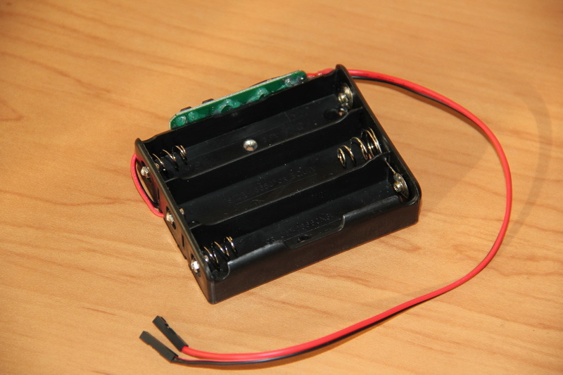
I started with the battery pack. The lithium-ion battery controller was “mounted” on hot-melt adhesive and the contact pins were soldered to it in accordance with the circuit diagram. I think readers will be interested in what was done and with what tool, so at the end of the article, under the spoiler, I posted pictures of some of the equipment used with my brief comments. Hot-melt adhesive was applied using a hot-melt gun. However, before that I had to do work to, so to speak, improve the reliability of this compartment. I will warn everyone who is planning to do something - it is better not to make my mistake and take more durable battery compartments. At one time I couldn’t find such compartments at retail, and when I found them, I collected a lot of them out of joy and simplicity of heart. But with them everything is not so simple. Because in this compartment, batteries with flat, non-protruding positive pads simply do not reach the contact. In addition, all spring-loaded contacts rotate, the contact is poor. Therefore, I had to screw in the M2 bolts, bite off the excess, screw on the nuts and tighten them to improve contact. But this didn’t seem enough to me, and I also thoroughly soldered all the connections. Because if something is done, then it must be reliable, so that it does not cause problems in the future and then does not come back to it again.
It should be noted that for lithium-ion batteries a conventional controller without balancing is used. This means that when one of the three batteries is charged, the controller will probably interrupt the charge of all batteries. In fact, it is simply a protection board against low discharge and overcharging of batteries and control of the discharge current. Therefore, it is advisable to use batteries with the same actual capacity. If you use a controller with balancing, then the selection of capacity is less critical and the batteries will be used more efficiently, but such controllers are more expensive and take up more space. How to choose batteries with the same actual capacity? After all, having bought identical batteries from the same series, even from brands, the capacity may vary by 5-10%, and Chinese batteries labeled 6000-8000 mAh are generally batteries with an unknown capacity. To measure real capacities, I used the OPUS BT-C3100 charger, which is quite popular in my environment. With its help, 12 purchased batteries were checked and three were selected, the range of capacities of which was minimal and did not exceed a few percent. The capacity of the LG LGABC21865 batteries was stated at 2800 mAh, but in reality it fluctuated in the range of 2400-2500 mAh (tested at a current of 700 mA).
A short digression in the form of reflection. The charger calculated the battery capacity for us, taking into account their charge to 4.2 V and discharge, if I’m not mistaken for the OPUS BT-C3100, to 2.8 V. Our batteries should not discharge less than the nominal value of 3.5-3, 7 V. That is, our working battery capacity is much lower than measured. This needs to be taken into account. Perhaps in the future, it is worth considering a battery pack of four batteries. Will it be possible to simply replace the battery pack and power supply to charge it? Let's figure it out. We will get a voltage range of 14.4-16.8 V. Voltage converters work with input voltages up to 32 V. Resistive dividers will give us a voltage range of telemetry signals of 4.3-5.1 V, which is slightly beyond the upper range of 0-5 Q. But this can be countered at the level of the control board - if the telemetry voltage is 5 V, then the battery pack will be almost charged after a while. On the other hand, if you lower the voltage to the motors to 6-7 V, you can discharge the existing battery pack more strongly and use the batteries more efficiently - in this case, you will only need to adjust one voltage converter. At first glance, there is scope for future research without changing the hardware at all, and how exactly to interpret telemetry signals depending on the installed battery pack - let this be decided at the level of the control board, that is, for now you don’t have to think about it.
I stripped the output wires from the resulting battery pack with special pliers (stripper) and crimped them into metal contacts using crimping pliers (crimper), soldered them for reliability and put plastic cases on them, obtaining BLS connectors. When soldering, a soldering station was used, POS-61 without rosin was used as solder, and no-clean FluxPlus NC-D500 was used as flux.


After assembling the battery pack and installing batteries in it, it will not output anything. This is how many lithium-ion battery controllers are designed - they de-energize the load when there is a short circuit, severe discharge, or excess discharge current. In order to “reset” the protection and bring the battery pack into working condition, you need to apply 12-12.6 V to the +P/-P contacts. The same must be done after connecting the batteries to the controller for the first time. After this, you can verify that the unit produces voltage if the batteries are correctly connected to the controller.
To charge such battery assemblies, there are power supplies with an output voltage of 12.6 V (3x4.2 V). With such a power supply, the batteries will be used more efficiently, although power sources rated 12 V can also be used. I already have such a power supply with an output of 12.6 V and a current of 5 A. If a similar source is purchased, then it is worth checking whether it corresponds it to the declared characteristics. The simplest test is to check the load capacity. For this I used ceramic resistors with a nominal value of 1 Ohm 10 W and 4.7 Ohm 10 W. Having assembled an assembly with a resistance of 2.5 Ohms from such resistors, I connected the power supply to it and measured the voltage at its output. With a calculated current of 12.6/2.5 = 5 A, my power supply produced 12.6 V - this is an excellent result. Chinese power supplies, which say something like 12V3A, often begin to “sag” by 10-20% with a load of only about 1 A.


By analogy, the switch and power socket were prepared.
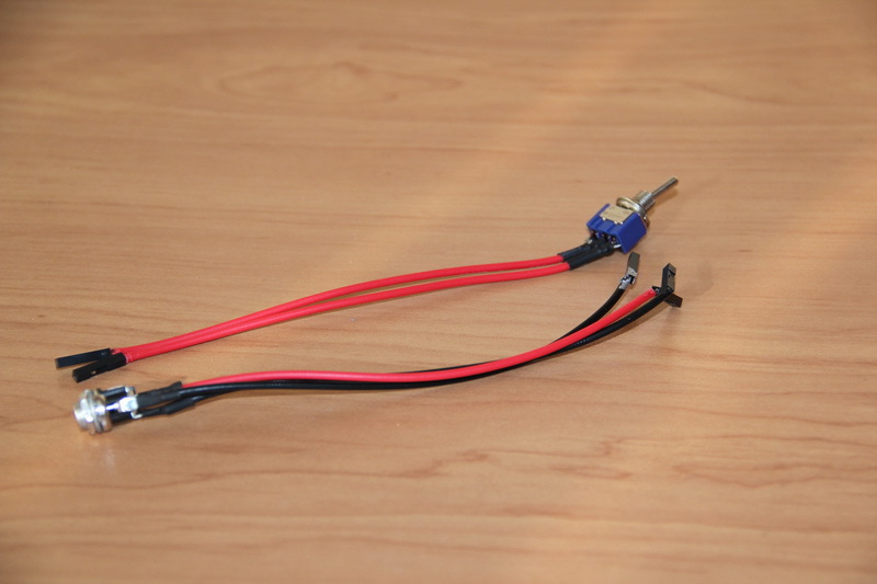
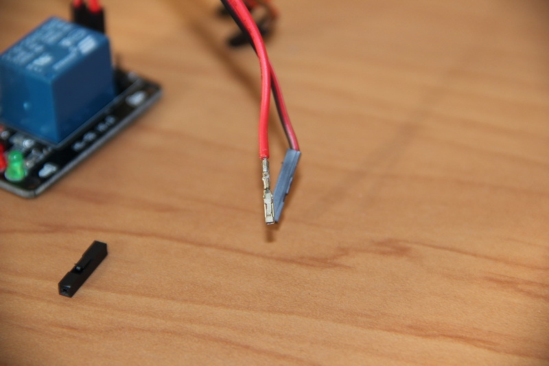
Using a hair dryer, the terminal block was removed from the relay module and the PLS contacts were soldered. To connect this module to the power board, I made wires - I stripped, crimped and soldered the power wires (through which the power connector and the battery pack will be connected) with a cross-section of 18-20 AWG. And for control I used the wires I had, with thinner cores, which can be easily searched for by the name “Dupont”.

The same was done with the motor driver.


“Legs” were soldered onto the DC/DC converters. It is worth mentioning that these contacts are made of a metal that can only be soldered well with active flux. Then, instead of FluxPlus, I use LTI-120, followed by wiping the soldering areas with a cloth moistened with isopropanol to remove flux residues.

Now we make our board with electronics. To begin with, it’s a good idea to imagine in general how and what will be connected on the board. That is, try to draw a circuit board.
[Power board]

Guess where I came up with and “licked” this board? We see two connectors on the board, two voltage converters. An additional jumper (removable jumper) has appeared, which can be installed by excluding the fuse from the electrical circuit - I did this specifically because of the banal absence of a fuse at the time of manufacturing the board.
Wiring the board is quite tedious and painstaking work. For power I used wires with a cross section of 18-20 AWG, for other signals - 26-30 AWG. Why exactly the breadboard and the hassle with the wiring? Because we still only have the first prototype. Something can change, so re-soldering the wiring is easier than cutting tracks and soldering all sorts of jumpers on a finished printed circuit board. Making a printed circuit board takes time - laying out, making a mask, etching, drilling, tinning, unsoldering - it is unlikely that this will take less time than making a board with “wiring”. Although the printed circuit board will be more reliable and look more professional.
For the same reasons, DC/DC converter modules are not soldered onto the board, but are made in the form of removable modules; ideally, after initial debugging, they must be additionally secured to the connector, for example, by dropping hot glue. It’s a good idea to use the same method to increase the reliability of the connections of all connectors. But while we have a prototype, it is more convenient for us to make everything removable, so that during future debugging we have free access to any important component and make it easier to replace it if necessary.


After manufacturing the board, it is necessary to check what is received for compliance with the circuit and wiring diagrams. Using a multimeter, I check the inputs and outputs for short circuits (it is better not to “ring” the contacts, but to measure their resistance, since in case of erroneous manufacturing or design, for example, a resistance of a hundred ohms may form at the input, which may not “ring” ", but its presence will be an error in the circuit and can cause big trouble), and I also make sure that everything is connected as needed inside the board.
After checking before assembly, you should make sure that the board will work normally when all peripherals are connected. To do this, you must first connect the battery pack, power switch, and flip the switch. The LEDs on the voltage converters should light up and nothing should burn out. While nothing is connected, it is necessary to adjust the output voltage of the converters. Then the power is turned off, the relay module is connected and power is applied again. In this way, all peripherals are connected step by step and under control.
Installation and connection of platform electronics
The electronics are ready. Now you need to install it. Remember, the seats of electronic boards were marked? Using a cordless screwdriver, holes are drilled in the required places. Then they are sanded using a mini drill with a sanding attachment. M2 screws are screwed into the holes. Washers must be placed under screws and nuts. In addition, I screwed on the second nut - the lock nut will provide a more reliable threaded connection and reduce the likelihood of it unscrewing. We are making a machine.
I note that the distance between two adjacent engines is quite large. This is an important point to note for the following reason. The fact is that the selected engines are without feedback. We simply apply a certain voltage level to them and they spin at a certain speed. But the characteristics of the engines may differ, which will certainly lead to problems when driving in a straight line. If the spread of motors is small and the robot will be controlled only by the operator, who can always correct the movement, then this may not be a significant problem. But if the spread is significant or the robot will have to travel a long distance “in a straight line” in automatic mode, then it is necessary to provide feedback. There is a series of GM25-370 engines identical in design, on which Hall sensors are already installed. What it is? On the back side of the engine, on the elongated shaft, a disk is attached with a magnet placed on it, which will influence the Hall sensor. After each full revolution of the disk, we receive a pulse signal, by processing which we can set the number of revolutions per minute. Thus, our platform contains a rather serious foundation for the future: it is possible to install motors with feedback, connect them to a power board that will power the sensors on them, and transmit telemetry signals to the control board - the control system can automatically equalize the speed of the motors.


I soldered the wires to the motors in accordance with the marks on them - on each motor there was a red dot near one of the two contacts. After receiving the engines, I checked them, but did not pay attention to the correctness of this marking. One of the engines, by the way, arrived defective and did not turn at all; the seller kindly sent me a replacement, which took at least a month to reach me. Subsequently, it turned out that the markings of one of the motors were mixed up, but this is not a problem - just change the polarity of connecting this motor to the power board. Looking ahead, I will say that the same situation happened with the connection of the “sides” - when the “forward” command was given, the wheels on the starboard side rotated forward, and on the left side, backwards. This can also be corrected by changing the polarity of connecting the desired motor driver channel to the power board. Changing the polarity of the connection - no need to solder or redo anything, you just need to swap the wires.
In order to eliminate electrical contact between the electronics boards and the case, I cut plastic plates from the blister pack onto the bottom of the platform.

Install the battery pack. The plastic is very soft and literally sags under the screw head; not even a washer can help, so I had to use a long metal plate.


All our bolts and nuts on the bottom side have slightly reduced the ground clearance and look quite aesthetically pleasing.


We insulate the bottom where the electronic boards are installed. We also cut out and place a strip of plastic on the metal plate in the battery pack to prevent even the battery case from scratching on the screw head, lithium is serious!


We install and screw the electronic boards and power connector.


It's a nightmare, how many wires... We connect the peripherals to the power board.


Platform control electronics
As you understand, in principle, the task is completed. The platform was received, everything worked out quite successfully. To control the platform, you can use any microcontroller, FPGA, Arduino boards, Intel Galileo, etc.I chose the Arduino Nano board, found an inexpensive and convenient expansion board for connecting peripherals and a bluetooth module for it. The basic idea is to control our platform from a smartphone via bluetooth. The expansion board, with its abundance of contacts for connecting external devices, will allow you to seamlessly connect future robot peripherals in the future.


Now we need to design and make a circuit board for these electronics. We will make a “sandwich”: a circuit board on which a bluetooth module and an expansion board are installed, into which, in turn, a board with a microcontroller is installed.

Compared to the power board, this board is almost purely a switching board. In the center, a cable is connected to the 18-pin three-row connector that connects this control board to the power board. From this connector, signals are routed to the required contacts of the expansion board, which then go to the required, pre-selected, contacts of the microcontroller. Also, 5 V and Vbat are output to separate contacts on the board. The board has power supplied to the bluetooth module, its Rx/Tx inputs are connected to the Rx/Tx inputs of the Arduino Nano board via an expansion board. The board contains a removable bipolar LED, the purpose of which is to indicate all processes related to power. The LED can generate a green and red constant glow, blink at a given frequency - this should be enough to indicate the normal voltage of the battery pack, its discharge, indicate the charging process and indicate the health of the connected power source.
In order not to get confused about what needs to be connected where, I schematically drew an Arduino Nano board and distributed the signals for it.

The Rx/Tx ports are occupied by a bluetooth module that operates using the UART protocol. If possible, IN1-IN4 signals are connected to digital ports - the polarity of these signals will determine the direction of rotation of the motors, and ENA/ENB to those ports that allow the output of PWM signals - these signals will set the rotation speed of the motors. The platform telemetry signal values will be digitized by analog inputs A0-A3 of the Arduino Nano board. The LED occupies ports A4 and A5, and it is connected via jumpers. The fact is that these two ports are needed for the simple organization of the I2C protocol and, if we need it, we can simply remove the jumpers. The LED can be “thrown” to other free ports or connected to the free ports A4 and A5 by a port expansion module (for example, based on the PCF8574T chip - it will provide an additional eight digital input/output ports, the module is controlled via the I2C protocol) to the pair pins of which and connect the LED. As a result of this distribution of connections, the ability to seamlessly connect SPI devices, digitize two more analog signals, and issue up to four PWM signals (for example, to control servos) is preserved. In general, I would like more free signals, but their number can be increased using the PCF8574T. In the end, you can use another Arduino Nano or replace it with a platform more suitable for the required tasks - this solution fully provides a certain minimum.
Our board also provides a simple connection to power: there are contacts for 5 V power and voltage from the battery pack (up to 12.6 V).
It is worth noting one nuance of the expansion board used for Arduino Nano. In principle, the expansion board allows you to run Vbat on it. A voltage converter is installed on the expansion board, which lowers the input voltage to 5 V and supplies it to the Arduino Nano board, the converter of which lowers it to 3.3 V, and this voltage is removed from the Arduino Nano board and distributed to the corresponding contacts of the expansion board. However, I did not do this and connected 5 V to the corresponding contact of the expansion board. In addition, the control LED on the expansion board did not light up at all if the Arduino Nano board was not installed, that is, this expansion board without an Arduino Nano is apparently actually inoperative. I didn’t look into the reasons, but I noted this point.
We are making this control board.


We install electronic boards on it.


We are preparing seats for our board. At the same time we install the switch.


And we collect everything.


Now you need to make a cable to connect the two boards. We also solder the power connectors for reliability. We check everything correctly and very carefully. 12 V should come to 12 V, and 5 V should come to 5 V. The pictures of power and control circuit boards show a “top view”, that is, if you turn the boards over, then on the bottom, soldering side of the boards, the contacts are swapped - this is necessary take into account when manufacturing the cable and passing the corresponding wires in it. I made the connectors simply: first, I assembled a series of wires with BLS connectors and wrapped them twice with tape. Then all two/three rows were gathered together and again tightly wrapped with tape. The result was a complete and monolithic connector. Plastic BLS connectors without contacts were simply placed into the unused connector pins.
After making the cable, all electronic boards are removed from the control board, and it is checked using a multimeter in the same way as the power board. We connect the control board to the power board and supply power. Using a multimeter, we carefully check the power contacts of all modules, inquire about the voltages of the telemetry signals - once again we make sure that everything is wired correctly. You don’t have to do this, confidently assemble everything, apply power and discover that in some, of course, mystical way, the 5 V and Vbat wires are mixed up and our Arduino board and bluetooth module have burned out. But it’s better not to repeat other people’s mistakes.
In the photo you can see that one of the red power wires is tinted silver. This is the designation of the conductor that transmits the voltage Vbat. When assembling a device, it is useful to make “keys” for connection. For example, do not intentionally solder one PLS contact on the connector, but spoil the mating socket in the cable or clog it with a piece of insulation - in this case, “foolproofing” is implemented, since then such a cable can only be installed accurately on the corresponding connector on the board simply because it will not install otherwise (the method does not provide a 100% guarantee - the Internet is full of pictures where particularly persistent individuals somehow manage to bypass such protection, using enviable persistence and their remarkable strength). I usually tint the corresponding pins on the connectors. It would be useful to mark the input connectors of the DC/DC converters on the power board and tint the corresponding sockets on the board. This would prevent the converters from being installed incorrectly, and if you use several colors, this would prevent the converter boards that form 5 V and 9 V from getting mixed up. You can use bright women’s nail polish for designation. This little rule greatly helps with the frequent assembly/disassembly of the device being developed at the stage of its debugging and testing.


We connect the cable to the power board.
I would like to briefly return to the beginning of the article, to the moment when we divided the platform into two parts and took out the control board “separately”. At the time, it seemed like a very balanced decision. However, looking at the abundant field of contacts on the Arduino expansion board, we understand that a good half of these contacts cannot be used with the current implementation of the platform - we occupied almost half of the input/output connectors on the Arduino board. And the microcontroller itself “runs” not just a program for issuing a pair of PWM signals to the motors, but provides complete control over the internal and external power supply of the entire platform. It’s worth thinking - maybe it’s worth including a microcontroller in the engine compartment of our platform? Bluetooth will be “given” to “above-platform” electronics that will control the robot’s devices, and an interface joint with it will be thought out. You can organize a UART protocol (it will take up two pins of the microcontroller) through which a data packet will be transmitted containing the direction and speed of rotation of the motors, as well as the general state of the platform... And you need to think carefully about the design, since we don’t have much space in the engine compartment... Although ... If you unfold and move the relay...
Well, that’s the end of my long and sometimes boring story. Only the “hardware” – the platform hardware – was developed, manufactured and assembled. The next part of the work is software. But this does not mean that you will only need to work as a programmer in the future. In the process of creating firmware for a microcontroller and debugging it, sometimes you have to take a multimeter, or even an oscilloscope, and figure out what signal is coming, where and in what form. Usually, it is at the beginning of this stage that errors and oversights of the “hardware” design stage appear to a greater extent. Our device is very simple, so if something doesn’t work, the error will quickly be found. Can you imagine what it’s like to work with really complex circuits? There you need to be much more careful and careful. It will also be necessary to organize a control interface via bluetooth with a smartphone - to come up with some kind of protocol for information interaction between the robot and the phone. And develop software that makes it comfortable and convenient to control the robot. But this is all another, separate story.
Some tools and equipment used
BOSCH GluePen. Glue gun. In Bosch terminology, it is a glue stick. Great mobile solution. It runs on an 18650 battery, which means there will be no problems with replacement in the future, and there’s nothing else that can break. It heats up quickly (15 seconds) and is ready for use; after switching off, it stops working almost immediately - the glue does not flow from it like in other hot-melt guns. Found application in everyday life and handicrafts. The only negative is the not so common glue sticks: 7 mm, high temperature 150...170C (DREMEL GG01 and GG03 sticks are suitable).

GROSS 17718. Insulation stripping tool (stripper). A complete analogue of the well-known model KBT WS-04A, which many manufacturers have sold 1-in-1.

HT-202A. Tool for crimping wires with connector contacts (crimper).

Solomon SL-30. Reliable soldering station. Soldering iron supply voltage 24V. Nickel plated tip. Precise temperature control.

SAIKE 8858. Aka Element 8032. Aka Yihua 8858. Aka ZHaoxin 858DH. There are variations between these models, but the design, heaters and electronics are the same. A good, convenient, cheap and really compact soldering gun. I bought it on an import site, with subsequent modifications from cheap Chinese products: shaking out any metal (!) debris, washing off the flux, soldering the contacts on the board, the power triac is placed on KPT8. So far I’m happy, the hairdryer blows like a hairdryer, the temperature and blowing speed are adjustable. In principle, the hair dryer is worth the money. This is a relatively recent purchase and the reliability statistics are still unclear, but I suspect that it will be suitable for infrequent work.

Metabo BZ 12SP. A very old screwdriver. Rarity. These are probably not for sale anymore. Allows you to do fairly delicate work thanks to good alignment and the absence of spindle runout.

Velleman VTHD02. Mini drill. Or, as they also call it, a Dremel (although this is just as incorrect as calling copiers copiers). Once upon a time I bought a set for a promotion; I was more pleased with the set of attachments than with the drill itself. However, she turned out to be quite good with some nutritional modifications. It works from the original power supply, but under load it is somehow difficult. About two years ago, of course, only temporarily, a mobile power supply was made from a compartment for four 18650 batteries with an adjustable output. The minidrill has become autonomous. With this nutrition, the mini-drill began to feel much better and turned out to be a very useful device on the farm.


Noble NB4000P-4. Multimeter. It is convenient because the wires are retracted completely inside. Acquired during difficult student years. That is, a long time ago. The wires broke off long ago - we had to “operate” from another failed multimeter. Now the wires have stopped being removed. The battery and fuse have been changed several times. It still works - amazing reliability with mediocre accuracy.

Fluke 179. High precision multimeter. A high-quality, convenient and, most importantly, accurate tool.

Received it as some kind of advertisement. Although... why not - where are my commissions then? All these tools are provided for general information. At one time, for example, I discovered strippers that turn the process of stripping wires from a chore into a pleasure, and I don’t regret buying a BOSCH GluePen at all. Maybe this small selection will help someone.
To assemble your robot, it is not at all necessary to have a variety of and expensive tools, although it certainly improves the quality of the work and brings greater pleasure from it. It is enough to have a regular soldering iron, several screwdrivers and a drill. After all, once upon a time, the author of this article, a long time ago, had at his disposal only pliers, a hammer, a couple of screwdrivers, copper wire, a brace (still there somewhere!) and two drills, pieces of telephone wires and a lot of blue electrical tape (often previously used), this was quite enough to make a simple car that, when you pressed a button, drove straight on its own.
Main components
Due to numerous requests from readers, I provide links (ebay/aliexpress) to the main components. Working links as of September 2016. I ordered everything six months ago (February-March 2016), so I recommend looking further - maybe now you can buy it at a better price.
Chassis, engines, wheels, fasteners - platform (choice of two colors) + 4 * (80 mm wheel + fasteners + engine (choice of three speeds))
Pay attention to the following kit - 130 mm wheel + fasteners + motor with Hall sensor
Pay attention to the capacious batteries (I’ve worked with them several times - these batteries’ real and declared capacities usually coincide, i.e. they actually have 3400 mAh!) - Panasonic NCR18650B 18650 / 3400 mAh / 3.7V / unprotected Module Bluetooth HC-06 5
0.9% It’s terrible - where is the culture of speech, the normal construction of sentences... the author needs to learn syntax and morphology! 2
5.9% I find it difficult to answer, or I’ll explain in the comments. 12
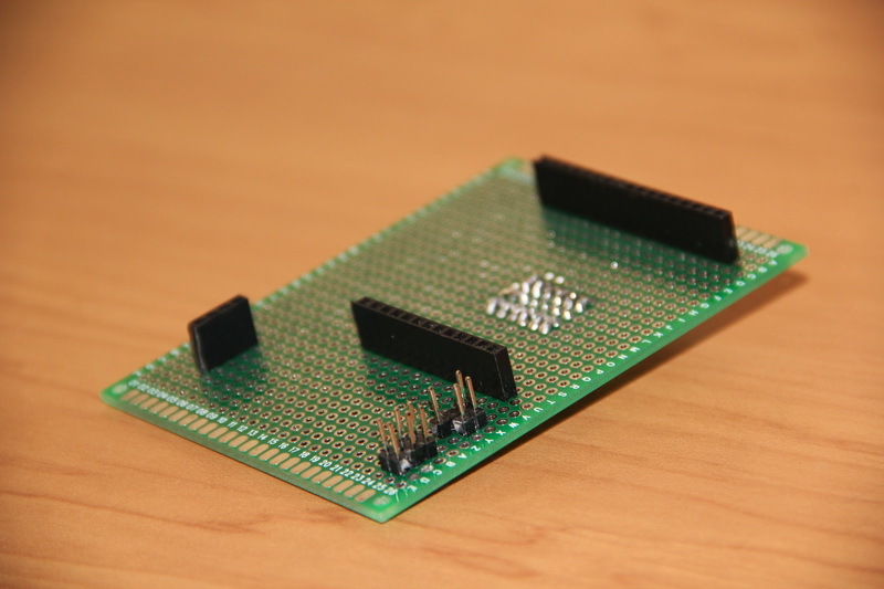
We got acquainted with the 105-Bender ZiChip device, learned how to work with the Tuner program and created several simple scripts. In order to move on and show how the 105-Bender firmware works with motors, we will need a cart.
To debug the device, I used my own, but for you, blog readers, this is not a very suitable option. Therefore, it was decided to use a ready-made cart for Arduino projects to demonstrate the device.
The store provided me with the cart and modules for this project. DiyLab . In this store you can buy many other interesting things.
The cart set is as follows
As you understand, the appearance of the cart does not matter. You can use a completely different design. This could be a 4-wheel drive cart or even a crawler cart.
In addition to the cart itself, we also need:

- Arduino board (Uno or Nano)
- L298N motor driver (or other type)
— photodetector and IR remote control (you can use a household remote control and TSOP4836)
- piezo emitter or small speaker
- Light-emitting diode
— breadboard and connecting wires (for ease of installation)
Assembling the cart and connecting the modules to each other should not cause any difficulties. The modules must be connected according to the diagram
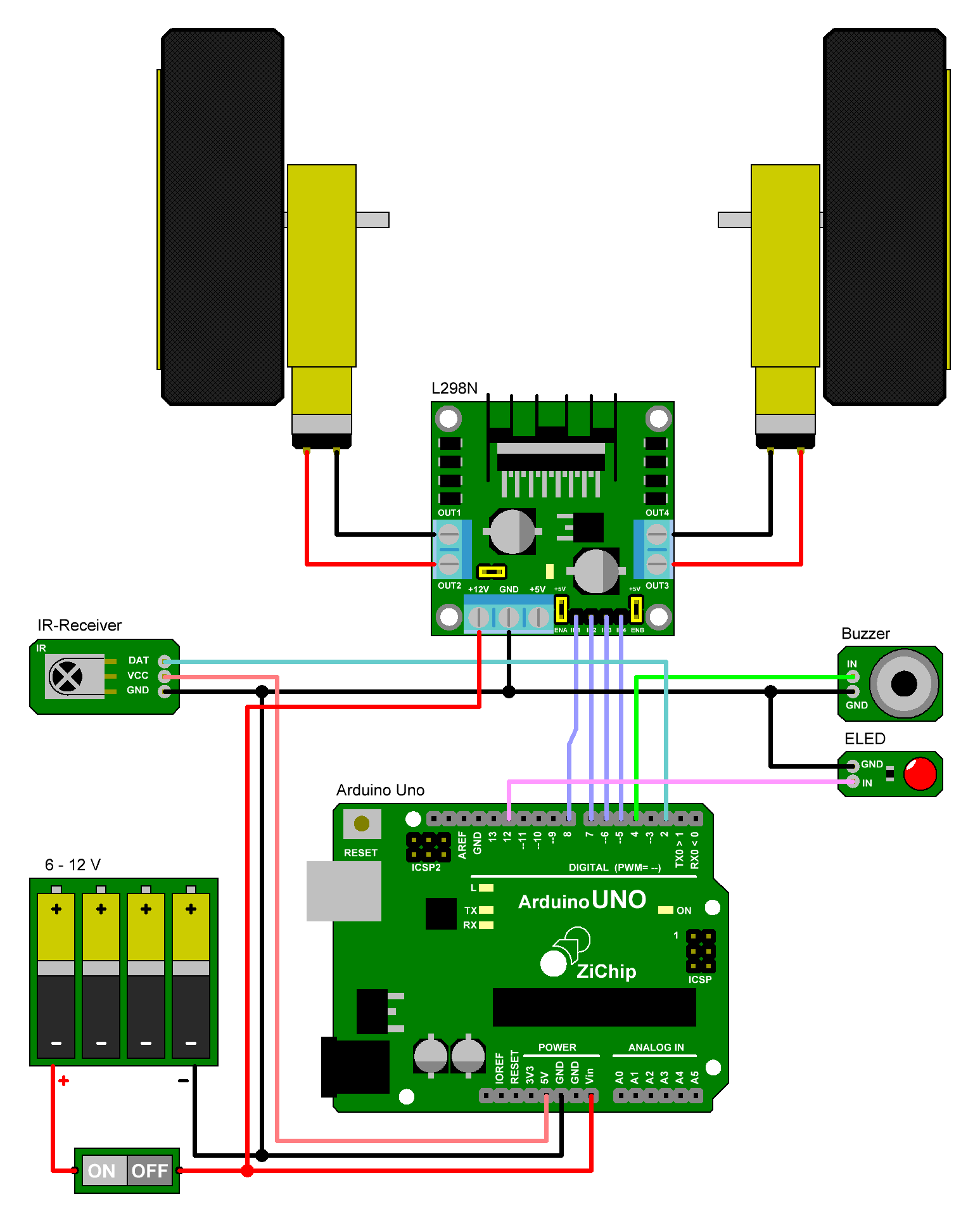
Use a breadboard to connect or connect everything with wires at once - as I did. The layout of the modules depends only on you - do what is most convenient for you.


3-watt LEDs with original collimators are used as headlights. When using two such LEDs connected in series, there is no need for a driver for them - when powered by 6 volts, the current does not exceed the nominal value. Single-watt LEDs can also be used. A field-effect transistor is used as a key for high-power LEDs. The speaker must be connected via a 10 - 100 µF capacitor
The trolley is assembled. In the next article we will launch it and teach you how to obey commands from the remote control.
(Visited 4,275 times, 1 visits today)