This article describes the Repair of high pressure fuel pump (high pressure fuel pump) for Mitsubishi Carisma cars with GDI direct injection system.
Required repair fluids and accessories
1. A bottle of Galosha gasoline or its equivalent (clean, unleaded, so as not to get poisoned);
2. 6 sheets of good sandpaper (sandpaper) with a grit of 1000, 1500 and 2000, each with 2 sheets. Preference for sandpaper with alumina abrasive, sometimes silicon carbide, it is softer, this information is usually located on the back of the sheet;
3. A piece of glass or mirror (approximately 300 x 300 mm) at least 8 mm thick. You can get it from the caretaker of any large supermarket, as a rule, there are always broken windows in stores.
If possible, it is better to use a calibrated grinding plate;
4. Cotton buds, clean rags.
5. A set of keys, including those for "stars". Special key for pressure regulator (see photo);
6. Plastic container for disassembled parts;
If there is no special key, then there is no point in trying to disassemble the regulator. No ersatz - substitutes are suitable!
Let's start repairing
We unscrew all the tubes, hoses, tees suitable for the pump. For the first time, it is better to mark the tube or fitting with its counterpart, for example, with nail polish (an equal number of dots or in another convenient way). When disassembling / assembling, nothing will be confused, everything is provided by the design so that if you try to assemble it incorrectly, either the length will not be enough, or the diameter will not fit, etc. When unscrewing the fitting coming from the low-pressure pump from the Karisma tank, gasoline may leak out a little, this is not a problem, in order to avoid spilling gasoline, place a rag under the hose before unscrewing it. You can also unscrew the gas tank cap to relieve excess pressure.
When unscrewing the fitting going to the fuel rail, cover the fitting with a rag, as there will be a small fountain of gasoline in all directions.
We unscrew the bolts securing the pressure regulator section (the part in which the sensor is installed and from which the tube goes to the ramp) to the central block of the pump (the so-called drive), 3 bolts. Without removing the regulator section, it will not be possible to get to the bolts securing the drive to the engine.
We unscrew the four long bolts securing the drive to the end of the engine and, gently shaking the pump, remove it from the seat.
 Very important, carefully look: the docking unit (end of the camshaft) and the ring with ears in the drive unit are not symmetrical! Although at first glance it looks very similar that they are symmetrical. In fact, the "ears" are slightly offset from the axis of symmetry. Incorrect installation (turning the shaft by 180 degrees), at best, will lead to a breakdown of the drive unit, at worst - to a breakdown of the camshaft!
A correctly exposed knot sits by hand in its nest, with virtually no gap. If you set the knot incorrectly, it will sit with a gap of 6 - 8 mm. When you try to tighten the gap with screws, the screws go hard, then a soft knock or blow is heard, and then the screws go freely. After that, you can disassemble and discard the drive! True, there is an emergency exit - there is a broken ring in the old Mitsubishi distributors. A distributor, compared to a pump, costs a penny.

In the photo on the right: 1 - high pressure sensor; 2 - channel for discharging part of the high pressure into the return; 3 - high pressure output to the fuel rail; 4 - pressure regulator block; 5 - mechanical drive unit; 6 - injection pump block.
Remove the injection pump assembly from the engine.
On the right photo we see the high pressure fuel pump assembly, removed from the engine. The pressure regulator section has already been removed in the photo (number 4 in the previous photo), there is a mechanical drive unit 5 and a high-pressure fuel pump unit 6, they are interconnected.
We unscrew 4 long bolts fastening sections 5 and 6 together and, helping ourselves a little with a flat screwdriver as a lever, we separate them. It is better to flush drive 5 with gasoline and fill it with clean engine oil, which you usually fill in your car. You need a little oil, 3 - 4 tablespoons, there is no more sense, since all the excess will flow out through the hole in the oil channel. For better drive lubrication, rotate the eccentric shaft.
Let's start the analysis of TNVD

With an E8 socket head, unscrew the two bolts under the "asterisk". We unscrew evenly, 3-4 turns, strongly pressing the unscrewed cover with your hand, since under it there is a rather strong spring in a compressed state. Carefully remove the cover.
In the photo on the left, the inside of the injection pump after removing the cover.
The photo is from the 3rd generation injection pump, but they differ only in the fastening castellated nut.
In the 2nd generation, there is no nut, and the inner package is not compressed by anything.
Carefully remove and fold the rubber rings separately. Using a thin screwdriver and tweezers, we take out the ring located in the groove of the wall of the chamber well. Without removing the ring, we will not analyze further.
With two flat screwdrivers, using them as levers, we take out the corrugation 7. We handle the corrugation very carefully!

After the corrugation, we take out the plunger 8.
We put all the removed parts in a plastic container filled with gasoline. For washing, we recommend using a mixture of Galosha gasoline or an equivalent with acetone in a ratio of 1: 1. The glands must be washed, thoroughly walked with a hard toothbrush. Especially the grooves of the corrugation, but do not overdo it so as not to damage the corrugation.
When the plunger pair (corrugation and central plunger) is washed, it is necessary to carry out a small but very necessary test. Its result will generally show the expediency of further actions. It is necessary to lick the thumb of the right hand well, put the plunger on it, with the platform on the finger, so that the finger is guaranteed to close the central hole and put the corrugation on top of the plunger. In a successful case, the corrugation will not fall on the plunger, the air cushion will interfere. The resulting knot must be squeezed several times between the thumb and forefinger. Three times he must spring.
This effect indicates a satisfactory condition of the plunger pair. If the corrugation is freely lowered onto the plunger and removed from it (remember the central hole closed with a finger), then further actions to repair the injection pump will be completely useless. Ejection injection pump.


Let's assume that your injection pump with a plunger pair is in perfect order.
We take out from the well with the plunger stroke limiter - a spring with a rod.
And a center pin.
And finally, the most important thing - three plates.
In our case, nothing special needs to be said about the state of these plates - everything can be seen in the photo below (photo on the left).
Grinding
 We take the prepared thick glass of at least 8 mm or a mirror of the same thickness, put it on any hard and even surface, for example, on a desktop. Next, we put the sandpaper on the glass with the abrasive up and with circular, spiral movements we remove all the workings, saddles and cavities on two thick plates, moving them over the sandpaper. We apply successively pre-prepared skins with a grain size of 1000, 1500 and 2000.

We carefully grind the medium, thin plate immediately with the 2000th sandpaper. No grinding, polishing and lapping pastes can be used, as as a result of their use it is possible to “lick off” the sharp edges of the holes!
After grinding, there should be no traces of old working on the plates. With ear sticks, carefully clean the holes in the plates from the remnants of sanding dust and dirt, you can use acetone. The condition of the plates after grinding is shown in the photo on the right.
We also carefully wash the pump housing itself from the remnants of dirt, sand and sediments of Russian gasoline, but we do not use acetone, but Galosha gasoline or its equivalent, since otherwise internal seals and rubber bands can be damaged.
We assemble injection pump
Very important: when assembling the injection pump, cleanliness should be as in the operating room.
We assemble the injection pump in the reverse order. Do not rush when installing the plates, do everything carefully and thoughtfully.
The sequence of the plates corresponds to the logic of the pump operation: a plate with four identical holes lies on the very bottom of the well, the holes are located within the spherical recess of the bottom.
Next comes a thin valve plate, and a thin plate with a large sector cutout covers it on top. A centering pin is inserted into the package of these three plates. If everything is set correctly, the alignment pin will pass through the plates, sink into the hole in the bottom of the well and protrude 1.5 - 2 mm. If the sides of the plates are reversed, the alignment pin cannot be inserted.

We put a plunger on top of the plates. We just lower it into the well and twist it around its axis a little until it sits on the protruding end of the pin and stops rotating. It is very important. If you do not put the pin in the plunger hole, then such a pump will not give the necessary working pressure, and the pin will jam the entire plate pack!
After installing the plunger in place in the side surface of the well, we install a rubber ring, then we lower the corrugation with an elastic band put on it onto the plunger. Carefully, the corrugation is hard (we remember how, during disassembly, the corrugation was removed using two screwdrivers as levers).
Perhaps you are interested in the question: how much does the thickness of the plates decrease during grinding? That is, what is the probability of getting a “dangling” package during assembly?
If the plates were polished at home, then the probability of removing a total layer of more than 0.1 mm from all the plates is minimal. But if the plates were given to the turner for grinding, then options are possible.
It's easy to check. In the 2nd generation injection pump in the assembled state, there should be a gap of about 0.6 - 0.8 mm between the cover and the pump housing. It is necessary to check not near the tightening screws, but in the middle of the case. In suspicious cases, a copper foil ring, 0.1-0.2 mm thick, can be placed on the base of the corrugation.
In the 3rd generation injection pump ("tablet") there is a standard copper ring and the package is tightened with a special castellated nut, there is no question of changing the package thickness at all.
We hope that this manual for the repair of the injection pump will return the former playfulness to your car again and eliminate the problems.
This material was prepared by a member of the Karisma Club - odessit Oh, for which he is very grateful.
Attention! The article is advisory in nature, the author of the material is not responsible for damage to your car during self-repair.
Mitsubishi GDI engine injection pump Page 1 of 57
FUEL INJECTION PUMP FOR GDI ENGINES.......... 2
PUMP DESIGN
DIESEL injection pump "NOT LUCKY"
BALANCING
WEAR OF INJECTION DRUM
UNSTABLE OPERATION XX
PUMP WEAR
"Sand" in gasoline.
LOW PRESSURE IN THE SYSTEM
PRESSURE SENSOR (error #56)
Pressure meter
Fuel pressure sensor
PRESSURE VALVE
PRESSURE REGULATOR
PRESSURE CHECK
Private pressure recovery method
DIMENSIONAL CHECK
REDUCER VALVE
REDUCER VALVE hexagon)
CORRECT ASSEMBLY OF THE PUMP
PUSHER-BLOWER
FILTER IN THE PUMP
OSCILLOGRAM OF WORK
A special case of pump repair
Collection of data from the Internet. (Loktev K.A.)
– – –
FUEL PUMP
GDI ENGINES
At the moment, four types (options) of high-pressure fuel pumps of GDI systems are known:– – –
Let's start our acquaintance with the so-called "single-section" high-pressure fuel pump installed on the 4G93 GDI engine, the working pressure in which is created using seven plungers:
photo1_1 "Three-section" injection pump and its device, operation, diagnostics and repair will be considered in subsequent articles. It is this injection pump that has been installed recently (after 1998) on almost all cars with the GDI system due to the fact that it is more reliable, more durable and, in principle, better amenable to diagnosis and repair.
In short, the principle of operation of this GDI system is quite simple:
An “ordinary” fuel pump “takes” fuel from the fuel tank and delivers it through the fuel line to the second pump - a high-pressure pump, where the fuel is compressed further, and already under a pressure of about 40-60 kg / cm2 it enters the injectors, which “inject” fuel directly into the combustion chamber.
The “weakest link” in this system is this high pressure fuel pump (photo1), located on the left in the direction of travel (photo2):
– – –
It is not difficult to guess for what reasons, because not only GDI owners, but also "ordinary" motorists began to understand that if some strange interruptions in work began in the car (in the engine), then the first thing you need to pay attention to is spark plug.
If they are "red" - who is to blame? Someone...
Only change, because such spark plugs are not subject to any "repair", as sometimes prescribed on the Internet.
FUEL Yes, it is precisely this that is the main cause of the "disease" of direct fuel injection systems. As well as GDI and D-4.
In the following articles, we will tell and show with specific examples and photographs HOW exactly and WHAT exactly our "high-quality and domestic" gasoline affects, for example, on:
– – –
PUMP DESIGN
... it's only "the devil is terrible when it is painted", and the GDI injection pump device is quite simple.If you understand and have some desire, for example ...
Let's look at the photo and see the disassembled single-section seven-plunger high-pressure pump GDI:
– – –
From left to right:
1-magnetic drive: drive shaft and spline shaft with magnetic spacer between them 2-plunger support plate 3-cage with plungers 4-cylinder cage seat 5-pressure chamber pressure reducing valve 6-adjustable high pressure valve at the outlet of the injectors-pressure regulator fuel 7-spring damper 8-drum with pressure chambers of plungers 9-washer-separator of low and high pressure chambers with refrigerators for gasoline lubrication 10-high pressure fuel pump housing with a solenoid reset valve and with a port for a pressure gauge The assembly and disassembly of the high pressure fuel pump is shown in the photo by numbers. We exclude only positions 5 and 6, because these valves can be installed during assembly immediately, before installing the drum with plungers (these valves and some of their features will be discussed in another article dedicated specifically to them).
After assembling the pump, you should fix it and start turning the shaft to make sure that everything is assembled correctly and rotates without "wedges".
This is the so-called simple "mechanical" check.
In order to conduct a "hydraulic" test, you should check the performance of the injection pump "for pressure" ... (which will be discussed in an additional article).
Yes, the injection pump device is "quite simple", however ...
Many complaints from GDI owners, many!
And the reason, as has been said many times "on the Internet" is only one - our native Russian fuel ...
From which not only the spark plugs "turn red" and with a decrease in temperature the car starts up disgustingly (if it starts up at all), but the "swallow" with GDI is wasting away and wasting away with every liter of Russian fuel poured into it ...
Let's look at the photo and "point the finger" at everything that wears out in the first place and what you need to pay attention to first of all:
Cage with plungers and drum with injection chambers
– – –
photo 3 (drum with injection chambers) and here it is already clearly visible - WHAT our Russian gasoline is ... the same reddishness, just rust on the plane of the drum. Naturally, she (rust), not only stays here, but also gets on the plunger itself and on everything "on which it rubs", look at the photo below ...
– – –
DIESEL injection pump "NOT LUCKY"
High pressure diesel fuel pump "out of luck"...Because it has only one plunger, and when it fails ("sits down", there is such a thing), then problems of a different nature begin.
The GDI high pressure fuel pump, which has such a name as "seven-plunger", is, presumably, devoid of such problems?
This is how to look and from which side.
A Mitsubishi car with a GDI 4G93 engine did not come for diagnostics, it "came". Hardly, slowly, slowly, because the engine worked somehow.
But the most interesting thing is the prehistory of the repair route - where this car returned from.
Collection of data from the Internet. (K.A. Loktev) Spring 2005 Mitsubishi GDI engine injection pump Page 9 of 57 Strange as it may seem, but before that this car was diagnosed in a dealership of this brand of cars.
And what's there?
Oddly enough, but according to the Client: "they couldn't do anything there."
Oddly enough, but they could not do the simplest and most banal - check the "high" pressure.
Okay, let's leave these arguments "overboard" of our story, although they lead to rather sad thoughts expressed by a "Moscow provincial" in a recent article on the "open spaces" of this Internet site, thoughts that confirm and convince: "Oh, there were people in our time!..".
Well, okay, what happened to this car and why he did not come, but "came on foot" to, as the Client said, "the workshop of my last hope."
"Instability of idling".
With all that it implies.
When we checked the "high" pressure, it turned out that it was the minimum allowable for "more or less" stable operation of the engine, only 2.5 - 3.0 MPa.
photo 1 Naturally, what kind of normal and correct work can we talk about in this case?
Let's pause.
And now look at photo 1: we deliberately stopped the workflow of checking the pressure in this very place, when the pressure gauge is not completely connected and rests on only one mount.
So - do - you can not!
And you, of course, understand why: the fuel (gasoline) pressure during engine operation is tens of kilograms per centimeter and, if God forbid, the fitting does not withstand and breaks, then ...
As usual, as it should be in this workshop: they removed and disassembled the high pressure fuel pump. They looked and "looked closely" with the help of an instrumental check on the condition of the plungers and found that they were practically "dead".
Like the plunger, so is the "drum".
Collection of data from the Internet. (K.A. Loktev) Spring 2005 Mitsubishi GDI engine injection pump Page 10 of 57 But the most interesting is yet to come...
The fact is that lately there have been too many repairs of these particular injection pumps with the replacement of individual parts, and it just so happened that for this injection pump it turned out to be almost impossible to find normal plungers suitable for the technical conditions ...
It's okay, because from any hopeless situation - there is a way out.
Only for this you need to have "a little" more gray matter and, most importantly, experience that comes with age.
The output was found as follows:
Picking the "right drum" is the first thing.
Second: pick up a few plungers that would "not let through" and a few - that would "crush".
Based on this, the "GDI-Solomon solution" was found - 4 plungers with dimensions of 5.956 2 plungers with dimensions of 5.975 1 plunger with dimensions of 5.990 photo 2 photo 3 In addition, look carefully at photos 2 and 3.
If in photo 2 you can notice the differences between the plungers, then in photo 3 - what?
"A drum is like a drum," as they say.
Let's pause and find out. And let's lift the veil of the "mystery" of the mechanism for selecting and selecting plungers and a drum a little, because the main question here is: how to choose, by what parameters, what to look at, how to look.
Photo 2. It can be seen that the plunger data have differences in appearance.
But not only in appearance, but also in its chemical composition, because of which the one at number 2 is wear-resistant.
Photo 3. As they say: "A drum is like a drum"? Color.
It's closer to brown. And this also indicates that such a "drum" is also wear-resistant.
Conclusion: it is necessary to select and install from such. Which is what was done.
The result of the work done can be seen here:
– – –
FUEL PRESSURE RELIEF SYSTEM
Yes, let's talk again about the pressure in the direct fuel injection system, about maintaining it and emergency reset in case of unforeseen situations ...– – –
photo 3 In the above photos you see an emergency pressure relief valve, which was no longer installed on the fourth generation high-pressure fuel pump.
From photo 3 it becomes clear that the device of this valve is quite simple, it consists of only two parts: a calibrated spring and a stem of a special configuration (photo 3).
The stem is inserted into the hole of the stacked plate valve (photo 1), and with the other side into the pusher-supercharger, where it rests against the piston (photo 2).
The principle of operation is just as simple: as soon as the pressure inside the high-pressure fuel pump in the high-pressure channels exceeds the reading of 90 kg.cm2, the valve rises under the influence of this increased pressure (remember, a calibrated spring) and then two actions occur simultaneously:
1. Overpressure will "smoothly" flow into the low pressure chamber. Collection of data from the Internet. (K.A. Loktev) Spring 2005 Mitsubishi GDI engine injection pump Page 12 of 57
2. The valve spring will be compressed and under its influence the other spring will be "pinched" which is located in the pusher-supercharger, and thus, during the pressure decrease, the pusher-supercharger piston will reduce its performance. As soon as the pressure drops to a value of 50 kg.cm2, the valve closes and everything starts working normally.
This valve is no longer installed on newer GDI models. It is difficult to say for what reasons, but most likely due to the fact that the "reinsurance Japanese soul" originally installed this valve, because such a phenomenon as an increase in pressure to 90 kilograms almost never occurs.
Another valve "operates at low pressure" photo 4 photo 5 photo 6 photo 7 photo 8 It is installed at the "outlet" of low pressure to the "return" (photo 7).
The appearance of the valve and its dimensions are shown in photo 4-5-6, and photo 8 shows an already disassembled valve (in principle, it is non-separable, but if you try ...).
This valve is intended for one thing: "do not dump fuel into the return line below the set value."
The manual says that this "set value" is equal to 1 Mpa, but Practice refutes this frozen opinion (erroneous translation? unwillingness to understand because the NAME already works on repaired cars?) and claims that this valve works at a value of 0.1 Mpa.
All mentioned valves do not require any special cleaning and adjustment, because all this (taring) is done forever during assembly.
Collection of data from the Internet. (K.A. Loktev) Spring 2005 Mitsubishi GDI engine high-pressure fuel pump Page 13 of 57 Of course, "a particularly burning technical soul" with Desire and Time can always try to change something and then see what happens.
One advice: before starting such work, carefully study Pascal's law ...
BALANCING
Such an expression as "balancing the injection pump" has not yet been mentioned in our articles, but now it's time to talk about it - what it is, why and how it is done by Dmitry Yuryevich, a specialist before diagnosing and repairing direct fuel injection systems, in an ANKAR car service.When the Client expresses such descriptions of a malfunction as: “It pulls badly, there is no power” and the like, then the first thing to pay attention to is the ignition system and the high pressure fuel pump:
photo 1 photo 2 photo 3 photo 4 Working on the diagnosis of direct fuel injection systems with "simple" equipment does not make much sense, because "proprietary" devices not only facilitate the diagnosis, but also allow it to be done more efficiently and quickly.
The above photographs just speak of this, well, tell me, how else can you more accurately understand the ongoing processes in the ignition system, if not with the help of the device shown in photo 2?
Or, photo 4 shows the display of the MUT2 dealer scanner, which allows you to "collect" the necessary parameters and simultaneously view them in order to make the most correct decision to determine the existing malfunction?
The expression "no pressure" is a real "sentence" of the high-pressure fuel pump, but in order to fully verify this, additional checks must be carried out so that later the "sentence" is not subject to appeal.
– – –
The most accurate check is "instrumental", when the high-pressure fuel pump, based on the readings of the scanner and additional checks, is disassembled, inspected and measured.
The reason for the "sentence" of the described high-pressure fuel pump was this:
– – –
photo 7 So, what can all this talk about?
Based on his experience, Dmitry Yuryevich can assume that such worn surfaces are obtained due to the imbalance of the plunger cage drum.
Although, if you look at it "just like that", then what can you see?
Almost nothing. But in order to really "see", one must have many years of experience, because only after it comes the second and complete definition: "See and Understand".
– – –
WEAR OF INJECTION DRUM
Many malfunctions of GDI engines arise, as already mentioned, due to low-quality fuel: frankly "dirty", or with "super" additives, or simply "inappropriate". Or the so-called "human factor".The photos below show just such a malfunction, which just arose for these two reasons: the “factor” and the fuel.
– – –
photo 2 Photo 1 shows two “drums” and if you look closely, you can see that the one on the left is kind of “smoother” and “more pleasant to look at” than the one on the right.
Following the arrows in photo 1, we will see that the plane of the left "drum"
differs, and quite strongly from the plane of the right "drum".
Photo 2 shows the same "reciprocal" parts directly adjacent to the "drum". The arrows in photo 2 (left position) show “scuffs” and scratches that arose due to the already mentioned “factors”.
Such a fuel pump will practically not work anymore. Because there will be no pressure, or it will be “on the verge of a foul”, as they say. “Metal does not speak”, it can only “tell” us what and how it happened. Let's try to consider the "case history" of such a malfunction?
Photo 3 shows a nearly life-size "erased drum" (constantly compare it with the same, but "smooth and fair" in photo 1 (left).
So, let's take a look:
Position "a" - this should be the entire surface. Position "b" - the first "development step"
Position "c" - the second "stage of production"
The arrows under No. 1 show the "width of the working" "c" - the largest and deepest.
As we know, in a high-pressure fuel pump, all its parts that come into contact with gasoline are “lubricated” with it. And they cool down.
photo 3 photo 4 Quality and again quality. Only this will “save” the planes (surfaces) processed with the highest accuracy from damage and, as a result, “save” the required pressure at the “exit” of the injection pump.
"Sand", one and very small, which may end up in the fuel tank and which, due to its small size, can "crawl" through the meshes and cleaning elements of the fuel filtration and get into the "holy of holies" of the fuel pump (photo 4, position 1, the remaining " traces" from "grain of sand"), first began to "work out" the position "b" (photo 3).
When the driver “drowned the gas to the floor”, the “grain of sand” moved closer to the center and began to actively “work out” the circle “c” (photo 3), resulting in such a Deep working (arrows 1, photo 3).
It’s a little unclear what the expression and consequences of this, like “gas to the polik” have to do with it?
With what's going on here:
Collection of data from the Internet. (K.A. Loktev) Spring 2005 Mitsubishi GDI engine injection pump Page 17 of 57
1. increase in revolutions (naturally) and the speed of rotation of the "drum".
2. "friction rate" increases, which requires increased fuel cooling, which may not be enough due to low performance of the booster fuel pump in the fuel tank, "clogging" of the fuel filter in front of the injection pump, "clogging" of the fuel "filter" in the injection pump itself, which and will lead to a decrease in the required amount of fuel not only for the "production" of pressure, but also for cooling and "lubricating" the rubbing parts of the high pressure fuel pump.
So the "active development" of planes begins.
Of course, all this is a bit approximate and relative, because no one has yet "looked" inside the fuel pump during its wear and we can only speculate ...
UNSTABLE OPERATION XX
Quite often, the engine starts to run unstable at idle and, in principle, only with the help of a scanner that "understands" GDI, you can determine the "area" of the malfunction: "low pressure".Without knowing the features of this fuel injection system or not having enough practice, you can look for a malfunction for quite a long time, going through or trying to fix exactly what seems most likely for this malfunction.
We will try to help in this matter and tell you about the most common malfunction, due to which the "unstable XX" occurs.
Let's look at the photo:
– – –
In photo 1 you see a "seat", and in photo 2-3-4 you see the "lamellar valve" itself, which is the "first stage" of pumping fuel to create high pressure.
The plates are arranged exactly as they are to be assembled.
At first glance, even these plates shown in the photo are in perfect order.
However, if you look closely (it's good, of course, to have an ordinary magnifying glass on your desktop), you can notice "something":
– – –
As we can see, the "shelf" of working "a" is much smaller than the "shelf" of working "b".
This is how wear occurs around these bypass holes. As well as due to quite natural wear and tear, and due to low-quality (dirty) fuel.
And then the middle plate of the inlaid reed valve will “incorrectly” adjoin the hole, approximately as we tried to model in photo 6.
Collection of data from the Internet. (Loktev K.A.) Spring 2005 Mitsubishi GDI engine injection pump Page 19 of 57 And based on Pascal's law, and also taking into account that the liquid (gasoline) is subjected to heat, vibration, that it may not be completely homogeneous and so further, it turns out that such a working on different holes may not be "centered", but shifted both to the left and to the right.
And now you can write or remember:
If one hole "does not hold" ... no, here it is necessary to stop and make a reservation, because recently there have been too many "criticizing elements" that may well find fault with this expression: "... does not hold ... hole ... ", - and the "bodyaga" will be divorced according to "exact" expressions, according to "incorrect" expressions, the Internet will again be clogged with statements about "fundamental disagreement with the author" ... and so on and so forth ... although, if you do not try to pull the expression out of the whole context, then everything is quite clear, isn't it?
So, "if one hole does not hold" (photo 7), then the engine will work at idle, but its speed will be - "walk".
If "does not hold" already two holes, then the revolutions of the twentieth will always "walk".
If "does not hold" three holes, then XX simply will not.
Well, there is no need to talk about the fourth. This will most likely not come to that.
Particular care must be taken when attempting to restore the middle spring plate.
You yourself understand that it is only necessary to bend it "embarrassingly", bend it and ... naturally, there will be no pressure.
All plates can be restored. Just don’t “rub” them all the way, it will be enough to “remove” black or rusty deposits with the help of lapping paste for valves and subsequently restore an even “landing” plane for the springy petals of the middle plate with the help of “skin-2000”.
PUMP WEAR
As our grandmothers used to say, remember?"You don't have to save on your health ...", - and if we slightly alter this expression in relation to a car, then we can say this way:
"Don't skimp on fuel."
Among motorists there is a very, very common opinion that "ninety-second is much better than ninety-fifth." And numerous examples are given that, they say, on the ninety-second it starts up better, and the consumption is less, and so on, and so on ...
This question is very, very controversial. You can say a lot and for a long time.
But we'll just give an example of how "GDI relates to ninety-two".
A client on a Mitsubishi "Legnum" of 1996 with a 4G93 engine (right-hand drive) came with such complaints about his car: "Something began to accelerate badly ... uncertainly idling ...".
The car was purchased only half a year ago and at first there were no complaints about it. And then it all started ... but somehow imperceptibly, "smoothly", if I may say so.
The first step was to check the pressure of the high pressure fuel pump.
It turned out that at XX it "presses" only about 2.0 Mpa (about 20 kg/cm2).
The captured Data Stream confirmed the initial mechanical test: "low pressure developed by the pump".
At rpm - yes, the high-pressure fuel pump "pressed" about 5.0Mpa, but at the twentieth, alas.
– – –
So, the "filter" was heavily clogged ...
photo 7 photo 8 By clicking on photo 7 we will see an enlarged image of the plungers. And we will determine, only visually, that they are very "worn out".
And to be specific, let's look at photo 8.
Arrows "a" and "b" show the stroke distance of the plunger, which is about 6 millimeters. At point "a" the diameter was 5.975 mm, and at point "b" 5.970 mm (remember the "ideal" dimensions: 5.995 mm).
All these pictures are just to show "the effect of 92 Gasoline on the GDI High Pressure Fuel Pump".
Yes, it was this gasoline that so affected the high-pressure fuel pump in just half a year of operation.
If you refuel "ninety-second" all the time, then the resource of the high-pressure fuel pump will be from a year to a year and a half (approximately, because there are quite exceptional examples when GDI "went" at "ninety-second" and for a much longer time).
So, why did this particular gasoline under that name become a "talk in the tongues" in our article?
"Sand" in gasoline.
This is exactly what you can say and call these words the cause of the above malfunction.
The word "sand" is very conditional, because it means "foreign impurities" to the fuel: mechanical impurities, water, corrosion products and everything that remains in the tanks on the walls - oil, fuel oil, diesel fuel and so on and so on.
All this is safely mixed during transportation, then merges into underground containers at gas stations and is also safely sold.
You can ask a completely fair question: "ninety-fifth - better?".
Yes, better.
Only to say "how much better" is difficult, because every opinion is subjective.
What conclusion can be drawn from all this?
There is only one: to fill up with gasoline other than 92, to purchase a more expensive one, because only under this condition can you both extend and "maintain the health" of your car.
Collection of data from the Internet. (K.A. Loktev) Spring 2005 Mitsubishi GDI engine injection pump Page 22 of 57
LOW PRESSURE IN THE SYSTEM
The name of the car was unusual: "ASPIRE", however, in Japan there are many unusual things. not just car names. Engine 4G93 GDI.How did you work?
Yes, nothing, in principle, if I may say so, getting used to the fact that many GDIs work, unlike "regular" gasoline engines, a little differently.
Sometimes "hard", as if all the hydraulic compensators "lay down", sometimes softly and quietly - "like a cat".
This one worked - "average", so to speak.
Nothing unusual. Like the majority. Checking the scanner showed. that "inside" everything is in perfect order, there are no fault codes, only ...
Yes, of course, they paid the very first and closest attention to the pressure, looked at what the scanner shows, and then double-checked everything with the "mechanics" and ... spread their hands in front of the Client: "We'll have to look at the pump and sort it out."
The pressure was about 4Mpa, and therefore there was a feeling that the engine, although it works, is still "somehow wrong."
Everything is correct, because Diagnostics is not only instrument readings, it is also the sensations of the Diagnostician himself, that he "sees, hears and feels."
And when disassembling the injection pump, this is what turned out:
– – –
You know how often it happens: being tempted by multi-colored labels and inscriptions under them (Instantly removes water! Eternal life to your motor!), And then succumbing to the reasoning of the seller, who needs only one thing - to sell, and then "grass does not grow", a person buys and ... fills.
On this engine, the Client also filled in "some" additives. What exactly - he himself, probably, finds it difficult to remember.
Okay, all this can be eliminated, including:
photo 4 GDI owners can't get away from this, and therefore it is necessary to carry out regular maintenance.
In addition, they "removed" the black carbon deposits in the tubules of the high-pressure fuel pump, cleaned it, or rather, "brought it" on the stove to the valve's working state. All together it took about two hours.
They put everything back together, started the engine and ... Well, here it is again "and".
Yes, the engine was running, but again "somehow wrong."
The instruments were all right, but the sensations were not.
There is such a thing as "give gas."
So, with "sharp gas" the engine developed speed "cleanly" (conditionally), but with "sharp moderate gas" the engine "spent".
Then already again paid attention to the ignition system.
– – –
After replacing the nozzle on the cylinder where the candle was "light" - everything, even the "feelings" smiled with satisfaction: "The car can be given away."
And what does the city of Perm have to do with the title of the article, you ask?
Only despite the fact that this car was driven from there to Moscow only in order to carry out maintenance.
No comment?
PRESSURE SENSOR (error #56) ... this is the most "tasty" trouble code for Thinking Diagnostics, because it gives free rein to both hands and thoughts.
There is no specifics in this fault code ("Abnormal pressure ..."), everything is only in general, which is especially valuable and attractive (naturally) for most of the Diagnostics.
So, let's first see what "the manual tells us", on which we will rely.
But - only rely on and no more.
Don't be guided.
This DTC is completely pressure related. Or its definition "through" the pressure sensor, or its "specific loss", which also determines the pressure sensor.
Fault code 56 appears in the case of:
1) if within 4 seconds (the figure is doubtful, but oh well), - the output voltage of the pressure sensor is 4.8 volts or more ... or 0.2 volts or less
2) if within 4 seconds the fuel pressure is 6.9 MPa or more ... or 2 MPa or less What does the "manual" offer us in this case and what causes of the malfunction are "seen" in it?
Everything is as usual and simple: a pressure sensor malfunction, a fuel injection pump malfunction, an electronic unit malfunction ...
Everything is as usual.
And the "usual" way out is also proposed: replacement of the high-pressure fuel pump.
But the most interesting thing is that the description of this DTC says that:
"This diagnostic code appears when there is air leakage into the high-pressure fuel line due to a fuel supply failure" As you yourself understand, the "root" of the problem cannot lie so close that it could be "gotten" so easily .. .everything, of course, is much more complicated and difficult.
It is not without reason that in "large" and "elite" car services they "ask" about two thousand dollars for the elimination of this fault code.
You ask, how much does this DTC "cost" in other workshops?
Much less. Because there is less staff there, fewer people have to "feed", so it turns out that DTC No. 56 "costs" several hundred dollars there. Almost 8-10 times less.
With the same quality and in less time.
– – –
photo 3 photo 4 Photos 1,2 and 4 show the appearance of the high pressure sensor itself.
In photo 3 - a "malfunction", formed as a result of the "human factor".
Of the remaining malfunctions, purely theoretically, it can be assumed that the valve hole may become clogged (photo 4).
Everything else, excluding "internal" faults, is the result of work ever done on the engine ("loose" sensor connector, oxidation of contacts, and so on).
Naturally, you should never forget that when removing the sensor and reinstalling it, you must always carefully monitor that its seal remains intact, otherwise the pressure inside the injection pump will change.
Abnormal (low or high) pressure in the injection pump can be formed for many reasons. It is difficult to list them all, so let's focus on a few, the most "bright" for now.
– – –
photo 7 Photos 5 and 6 show the high-pressure regulator plunger, photo 7 shows the main blower plunger with a separating corrugation.
In photo 5, numbers 1 and 2 show the working surfaces of the plunger and, if you look closely, you can see that these surfaces are different. The left is more dirty than the right. How? The so-called "resinous deposits" (gasoline, my friend, gasoline ...).
Collection of data from the Internet. (K.A. Loktev) Spring 2005 Mitsubishi GDI engine injection pump Page 27 of 57 In photo 6, the arrow shows the wear of the working surface of the same plunger. This can happen as a result of ... yes, again, the quality of the fuel. For example, a grain of sand (quartz, by the way) and that's it, a few tens of kilometers and the pressure in the pump begins to drop.
You don’t even need to look closely at photo 7 - a crack, which was formed again as a result of the “human factor” (during disassembly and assembly of the injection pump), and the internal pressure in the injection pump decreases and “helps” the oil mix with fuel. Naturally, what kind of "normal" engine operation can we talk about with such malfunctions? He will not "pull" and "like a steam locomotive" will smoke ...
With reduced (increased) pressure in the injection pump, the ECU can "cope" in only one way - signal this "through" diagnostic trouble code No. 56.
I would like to advise you something else: be very careful about translated "manuals" in Russian, even, for example, if they are "from Rolf".
After all, people also translated and ...
For example, let's see what the "manual" on GDI says about "our" pressure sensor in the "Emergency Modes" section.
"When the self-diagnostic system detects a malfunction of one of the main sensors, the system enters the emergency control mode (pre-set control logic) so that the car can continue to drive safely to the service station."
Fuel pressure sensor
1) Fuel pressure is assumed to be 5 MPa (in the event of an open or short circuit in the circuit)
2) Turns off the fuel pump relay (in case of non-compliance with the norm of high fuel pressure).
3) Shuts off the fuel supply (as if the pressure is too low or the engine speed is above 3000 min-1).
Logically, you can take point number 1 on faith, yes, everything is correct. The ECU in the case of "open or short" can "make" such a decision, it can be programmed with it.
But points No. 2 and 3 completely contradict each other, because if (see point No. 2), then it turns out that the pressure sensor is working and detects high pressure.
The same goes for point #3.
The best thing in this case is to refer to the "manual" in the "native", English language.
Because, speaking critically, the translation was made, of course, reversely, but ... stupidly. Without knowledge of the features of this system.
It should be noted that in later models of cars with GDI, the fault codes (their number) are slightly expanded, there is already not a binary code, but OBD2, which allows you to more accurately determine the malfunction and fix it.
PRESSURE VALVE
1995 - The first mass-produced GDI (Gasoline Direct Injection) engine with gasoline direct injection was developed. The "GDI" technology is recognized as the technology of the year in Japan, Germany, England.In 1996, the GDI engine was put into series production. The first serial model of the car Galant 1.8GDI appeared.
Collection of data from the Internet. (K.A. Loktev) Spring 2005 Mitsubishi GDI engine injection pump Page 28 of 57 By the end of 1997, GDI engines were installed on Galant, Pajero, Pajero Sport, Carisma, Pajero Pinin, Space Wagon/Runner. (World News Feed) So, GDI technology began and won almost the whole world with its undeniable advantages, the main of which is environmental safety.
In the open literature, on the Internet, a lot and often talk about GDI, but all in general terms and vague reasoning. It was also mentioned that "the engine is running at high pressure."
And what exactly is it, “what is this “pressure” eaten with, how this system is implemented ... not a word, not a half-word.
We will try to fill this gap a little and tell in this article about the valves that transmit and maintain this very “high pressure” in the GDI system.
Let's start with the "ordinary" solenoid valve, which is located on the "body" of the injection pump, because it is from it that the "song of songs" of the GDI itself begins:
photo 1 photo 2 In photo 1 this valve is number 2, and in photo 2 this valve is in "full height", you can even make out the serial number. For a replacement? No, you know, the valve is so simple in its design and so reliable in manufacture that it almost never fails.
The purpose of this depress valve (pressure relief valve) is one, and it only works in two positions - "ON - OFF", that is, it opens and closes.
However, the so-called "algorithm" of his work is very interesting ...
Collection of data from the Internet. (K.A. Loktev) Spring 2005 Mitsubishi GDI engine high-pressure fuel pump Page 29 of 57 There was (and probably still is) an opinion that the depress valve "works" when the ignition is turned on.
No, this valve only opens when the ECU receives a signal from the alternator and only at that moment the ECU commands the depress valve to open it. (Immediately there is "room for thought, isn't it? .. there is no signal from the generator ... there is no signal from the ECU to the valve - this is the reason for the high pressure fuel pump fault code. In addition, it is quite possible to speculate about these faults and this one, also no less likely: the valve is constantly "closed" or constantly "open" *due to certain reasons* - what do you think will happen because of this? Let's think ...).
When opened, the valve "resets" the existing pressure in the high-pressure fuel rail back to the tank, that is, it restores the "starting" pressure position in the system for the operation of the high-pressure fuel pump (this is exactly what should happen: before the high-pressure fuel pump starts operating, the fuel rail "should not contain high pressure ").
And now is the time to look - "what goes where", that is, the purpose of the high and low pressure lines:
– – –
And remember, we once talked with you on the "open spaces of this site" that the amount of "injected" fuel will always be different at different pressures? (By the way, a similar question was asked recently at our Conference - the Thought is moving!).
This is exactly what happens when you unscrew or tighten this hexagon.
Is there something to think about? But!
The manufacturer (MITSUBISHI) and its dealers (naturally, bread - then they take from whose table?), - they all recommend and highly strongly advise "to turn the hexagon only in the direction of increasing pressure" If the engine starts to work "better" with reverse action, then the Manufacturer strongly recommends replacing the entire assembly.
But ... we are "Russian people", aren't we? Further, probably, one can not say, not even predict - what the RUSSIAN DIAGNOSTIC will answer to the recommendations of the Japanese "car industry" ...
It remains to disassemble two more valves, which serve to divide and connect the high and low pressure chambers, but there are no photos of them, so we'll leave it for later.
PRESSURE REGULATOR
... all liquids and gases transmit the pressure produced on them equally in all directions ...This is exactly how - strictly considering and relying on Pascal's law, the GDI high-pressure fuel pump was created.
Liquid (including gasoline), a practically incompressible substance, we know this from school. In the fuel pump, it does not stand still, it constantly moves, contracts, mixes, heats up and cools down, friction against the walls slows it down in one place and "turbulates" in another ...
This is where pulsations and jumps "in pressure" arise, which could "bury" the very idea of GDI in the very bud ...
Could, if it were not invented and patented (for GDI) several devices that dampen oscillations, pulsations and pressure surges inside the GDI high pressure fuel pump between the so-called "nodal" points, the first of which is "inlet to the low pressure fuel pump" (photo 3, arrow).
Yes, this is where the fuel comes from the low pressure pump from the fuel tank.
Please note that it is in this place that the so-called "filter" is located, which we talked about in previous articles (the arrow in photo 4 shows exactly its "seat" ... and now you can calculate how many such "filters" cost on the GDI high-pressure fuel pump and draw certain conclusions about what must be cleaned, and what - "later").
After the filter, the fuel is "processed" by the low pressure fuel regulator:
Photo 1 - regulator detail
Photo 3 - "seating" place of the regulator In contrast to the "ordinary" low pressure regulators (MPI system, for example), this regulator is a little more complicated. It is not of the "membrane" type, but of the "piston" type.
Internal surfaces - precision. It is here that the initial "smoothing" of pulsations begins, which can occur during the operation of the booster pump (in the tank) and the movement of fuel through the fuel line to the injection pump.
The very first "pressure troubles" can be expected here. Let's look at photo 2, which shows the regulator spring (in photo 1 it is the fourth from the left). Can you imagine WHAT was inside the regulator if the spring was of such a "reddish" type (fuel, my friend, fuel! ..
during the repair of this high-pressure fuel pump, "great" words were said:
"Not water in fuel, but fuel in water...").
– – –
However, the "regulator - it is the regulator", its main purpose is different, it only "helps", at least a little, but it helps with its entire design to smooth out fuel pulsations to the main device called the "damper chamber":
photo 7 photo 8 photo 7, position 3 - damper chamber of the high pressure fuel pump (1st stage) photo 8 - detailing of the damper chamber As you can see in photo 8, the chamber itself is quite simple and consists of only two metal parts. The arrow shows the hole (throttling hole), through which the fuel first fills the chamber (high pressure), and then (recall Pascal's law) - "smoothes out" possible pulsations.
However, one damper chamber is indispensable and the "Japanese mind" also came up with the so-called "second damping chamber" located next to the fuel pressure sensor:
– – –
If the damper chamber of the first stage is quite easy to disassemble (pry off with a screwdriver, swing), then to disassemble the DC of the second stage, you will have to use compressed air, it “sits” so tightly.
Some difficulties may arise when assembling the low fuel pressure regulator, so you can use photos 1, photos 5 and 6, but also be sure to look at the following photo:
showing the final adjustment and installation of the inner case.
Arrow 1 points to the cutout, which, when reassembling the pressure regulator, must be aligned with recess 2.
Otherwise, the controller will only be called a controller...
PRESSURE CHECK
Disassembling the pump, in principle, is simple ... it’s just as easy to assemble it, but such a thought always irritates, agree: “how is the pressure there? What happened? Will it work and how to work?”.All this can be found out after a preliminary check of the injection pump "for pressure".
After it was "reanimated", assembled and ready to be installed on the engine.
The technique here is simple and everything can be perfectly understood from the photographs below:
– – –
photo 3 We install the assembled pump in a vise, fix it ... yes, we do not describe the "manual" procedure, that is, as described in the "manuals", because there, of course, "special test equipment" is required - but we will not mess with your head, right? Such "devices", in principle, are not required at all (especially how much they cost in dollar terms ?!), you can perfectly get by with "ordinary" vise (in the picture, however, the vise is "purely" from SNAP-ON, but this who already has something ...).
So, we fixed the injection pump in a vice and with a prefabricated adapter we connect the "high pressure", that is, the input-output to the nozzles (photo 1).
After that, we begin to pour fuel (gasoline) into the low pressure "inlet" (photo 2, arrow), while simultaneously scrolling the fuel pump shaft. You can scroll with your fingers, or you can also use a specially made "device" (photo 5), that is, a slightly modernized "24" head.
We fill in the fuel and scroll the pump until the bubbles run out (photo 3), that is, there is no air inside the pump.
– – –
So you have to re-disassemble everything and look more carefully and carefully.
As you can see, the described procedure is quite simple, you just need to make a few "adaptations" that you simply cannot do without.
A private way to restore pressure Eugene from Moscow, suggested a rather interesting way to "restore" pressure.
How and what to do in this case - in his picture:
Let's say streamlined: "we do not confirm and do not refute."
Because everything should be decided by Practice, that is, someone should try it all, try it and give a conclusion: "it works!".
Or vice versa...
Wouldn't it be easier to have these spare parts on your desktop:
– – –
DIMENSIONAL CHECK
Micron tolerances can quickly get used to when dealing with GDI.Because the lines on the scanner display are automatically translated into microns in the mind.
A little strange, you must admit: the scanner has never shown any measurements in millimeters or microns, right?
– – –
photo 1.a photo 2.
a First, just "listen": "clicks or not?", and then, if there is any suspicion, remove and disassemble. Visual verification is always more reliable than mere guesswork.
Only when checking the valve it is necessary to hold its moving stem, otherwise, when voltage is applied to the valve, it can fly out and scatter around the workshop.
It is also worth checking the "filter", pay attention to its condition and the "presence or absence" of contaminants.
In the photo below, you can see that this "filter" at the bottom of the mesh has the so-called "hairs" (the rest are not visible, but we can assure you that there are a lot of them on other sides), which, of course, "do not add pressure" :
– – –
photo 5 Looking at the plunger in photo 3 one cannot immediately tell which one is "good" and which one is "bad". True, if you look closely, then the left one seems to be a little "smaller"?
For this, there is an instrumental check (photo 4).
And now the numbers that are called "dry", but they say a lot (by the way, take a closer look at exactly which place is measured on the plunger, so as not to be mistaken in your measurements later).
The normal diameter of a new plunger is 5.995 mm.
In photo 4, the diameter of the measured plunger is 5.975 mm.
The difference is 20 microns. Is it a lot or a little? Can this plunger be put back?
Collection of data from the Internet. (K.A. Loktev) Spring 2005 Mitsubishi GDI engine injection pump Page 40 of 57 Work practice shows (and proves) that it is possible. Up to size 5.970 mm.
If during measurements it turns out that the diameter, for example, is 5.965 mm or even less, then such a plunger can be folded into a separate box "for history", because with such a diameter "there will be no pressure."
You can also "keep in mind" and such a table (pay attention to the color change):
But even with a size of 5.975, one must be careful, because such a size is, as they say, "at the limit".
Of course, as they say: "There is still a chance of success", but still ...
Here it is already necessary to look at the development of the "drum" ("inside gauge", for example), inside it, where the plunger "walks" (photo 5).
And if the holes there are "not worn out", if there is such confidence, then "an attempt is not torture"?
The article "if you knock and see" provides interesting arguments "etka 602" about the "repair" of plungers. Other proposals were also sent, other options for how to "restore" the plunger, up to processing the surface of the plunger in some self-made "electronic bath".
It seems that such or similar hopes should be abandoned ...
Because joking around with such micron tolerances, not having a solid tool base and trying to "repair" GDI exclusively "on the knee" - all this will only lead to negative results, a waste of time and effort.
photo 6 photo 7 By the way, if you have already decided to disassemble the fuel pump and see "how it spins inside", then do not forget to check the high pressure regulator, look at the condition of its plunger and, if necessary, "grind" it.
This is the only "device" (from the English device) in this high-pressure fuel pump that can be "lapped" (photo 7, mek at work). The skin is used imported, "two thousandth".
Note: How to say correctly: "plungerA" or "plungers"? Hard to say...
however, whoever likes it. Slang changes in every time zone...
Collection of data from the Internet. (K.A. Loktev) Spring 2005 Mitsubishi GDI engine injection pump Page 41 of 57
REDUCER VALVE
... one can imagine the feelings and state of that person who ended up in the night forest tens of kilometers from the city driving a "dead" car.With GDI engine.
And the only thing he could hope for was that his "cell" was still working and he could call the Master, who...
Hardly. But hope ... it always - dies last.
The conversation was short and "productive": ... four turns ... yes ... turn it off ... and now start ...
This is a real story that happened quite recently and had its continuation in the workshop, where the diagnosis was already accurately established and the "treatment" of this GDI was prescribed.
And to make it a little clearer what we are talking about, we need to bring a few photos:
– – –
Photo 2 shows an enlarged view of the pressure reducing valve, "what is spinning". For four turns.
Take a look and stock up (just in case?!!) with such a "cunning" key.
Unless, of course, you are the owner of GDI and are afraid to get up in exactly the same way as described above. At night, in the forest ... brrr!
By the way, on cars produced before 2000 - a hexagon. "On three".
But these are all "emotions", let's try to look "inside" and see - "how is it spinning there"?
If we unscrew this valve, then the pressure in the "return" will decrease. Four turns is approximately "MPI pressure", i.e. about 4-6 kg/cm2.
And the engine will work for us in the "mode of operation on the stoichiometric composition of the air-fuel mixture" (approximately).
And the reason for this, Figure 3 is the so-called "injector control unit".
And if it was possible to start the engine "in MPI mode", then the conclusion is practically unambiguous.
The main "disease" of this block is the failure of the "GDI mode control module", that is, the mode of operation on an over-lean air-fuel mixture.
You can try to "understand" and define his "disease" by such signs, for example:
1) difficult engine start
2) after a "difficult" start, the engine runs "extremely uneven" and unstable, it seems that the problems lie either in the incorrect installation of the timing belt, "clogged" injectors, etc.
The scanner does not detect such malfunctions.
For what reasons, what is a "GDI mode control module" and much more - everything will be discussed in other articles.
Afterword: ... the conversation "from the night forest" at the beginning of the article was not mentioned by chance, no. The owner of the car turned out to be a smart person and quickly figured everything out. It's nice to talk to someone like that!
Collection of data from the Internet. (K.A. Loktev) Spring 2005 Mitsubishi GDI engine injection pump Page 43 of 57 understand: "how can you not understand this, the simplest?".
If a person starts repairing not “just” engines, but GDI, and even more so Diagnostics, then all this by itself predetermines a certain Level of Knowledge of this person.
And if he starts asking, clarifying, asking again the "most-most" simplest, then a completely fair question arises: "Why does he need this?"
For - "just money"? For "experience"?
But judge for yourself: how can you gain and "accumulate" experience in the case when there is no "base", for example, the concept of "just" a four-stroke engine" or what is an "ordinary" bypass channel, IACV is an abbreviation ... and so on, and so on...
This is a rarity - when they go to school right away in the tenth grade.
REDUCER VALVE hexagon) Surprisingly, the fact remains: the part of the GDI high-pressure fuel pump shown in photo 1 costs almost the same as the injection pump assembly itself - unless, of course, you buy from dealers:
photo 1 Speaking about the GDI injection pump, one can never say specifically: "this part is "responsible" for pressure", no.
In this fuel pump, almost all the "details" are related to either creating or maintaining pressure.
There are many ways to determine the "guilt" of a certain part (assembly) of the injection pump.
For example, the pressure control valve shown in photo 2:
– – –
photo 3 Let's start to twist it.
If, upon reaching a pressure of about 60 kg \ cm (plus or minus), the operation of the engine stabilizes, then it can be said (assumed) with a certain degree of certainty that the reason lies in the pressure control valve (during twisting, it "crossed the hole of production" and began to work fine).
Otherwise, if we tighten the hexagon almost to the end (to the “stop”) and the engine does not stabilize, then the cause of the malfunction must be looked for further, maybe it is necessary to “make a pump”.
And in this expression "make a pump", there are a dozen or more malfunctions, a good half of which have already been described in previous articles.
Note 1: Repair of a similar fault "at the dealer" and according to the dealer's manual, very "simple" - "REPLACE".
Note 2: Repairing such a malfunction in a workshop where people are accustomed to relying on Experience and Craftsmanship will cost the Client almost ten times less ...
Note 3: Recently, expressions such as "dealer repair" and the like are often used in articles. And not only in articles, in our life this type of repair takes a large expense item for certain circles of Clients.
We will talk about this specifically, but for now, we note that this type of repair, called "dealership", it may reduce the repair time (replace the assembly assembly or look for a malfunction - time is different, agree), but this type repair at the same time "dries the brains", because there is no need to think anymore, you just need to strictly and blindly follow the instructions developed "there".
And this instruction ("manual"), not always justifiably recommends in the case of "there is no resistance there or there" - "replace the assembly" this or that unit or assembly.
Manufacturers will try to "pressure" small workshops, destroy them in the bud, the only question is the time and the amount allocated for the "breakthrough" of a certain bill (everything will be done under the guise of "caring for the safety of vehicles" of OUR people, most likely ... ).
And this should happen. Sooner or later. Because the Thinking Diagnostician is unprofitable for large volumes of repairs. Already now there is a certain flow of Clients from dealers to car services, where the Thinking Diagnostician works.
Russia will be "crushed" in this area as well...
Required note:
As well as to this article, and to everything else that is in the section.
Collection of data from the Internet. (K.A. Loktev) Spring 2005 Mitsubishi GDI engine injection pump Page 45 of 57 ... let's just say: not "many", but already "enough" letters were received with almost the same question (or reproach), which can be expressed in the "general" as follows: "I did everything as you wrote in your articles," but my car still "does not drive."
I can assure you - in this case, she will not "go".
Understanding not only the work, but also the GDI repair algorithm is formed like a mosaic - from all this many articles that have already "seen the light of day".
But they, one might say, are only the "visible part of the iceberg", everything else is hidden by the past years of accumulated experience, in particular, our moderator of the GDI section, Dmitry Yuryevich.
To follow what is written for a particular case (to do so), in isolation from one's own symptomatology, is a hopeless thing and in the end leads to a dead end.
This, by the way, practically nullifies the attempts of the "diagnostic money-makers" to use our website and the Forum to "make personal money" on someone else's experience.
Both the site and the forum can only help the person who constantly keeps a "hand on the pulse" of diagnostics. Only for such people a small hint in half a word is, at times, of decisive importance.
CORRECT ASSEMBLY OF THE PUMP
How to most correctly assemble the injection pump GDI– – –
photo 11 photo 12 Photos from #1 to #12 are located exactly as the assembly of the three-section GDI high-pressure fuel pump is in progress.
Photo 1: we prepare the "seat" for installing the plates of the inlaid reed valve Photo 2: we install the pin on which the valve plates will be "dressed" Photo 3: installing the bottom plate Photo 4: installing the middle plate Photo 5: installing the top plate (pictured) the numbers show all three installed plates) Photo 6: installation of the pressure reducing valve Photo 7: installation of the "pusher-supercharger" base Photo 8: surfaces are lubricated with a special spray Photo 9: installation of the "pusher-supercharger" Photo 10-11-12: installation of the mechanical unit photos 10-12 let's stop a little in more detail ...
The fact is that, both during assembly and during disassembly of this high-pressure fuel pump (especially for the first time), not entirely correct actions may occur that will lead to a breakdown of the "pusher-supercharger":
– – –
in this last photo you see the consequences of the so-called "human factor" already mentioned in the previous article. Yes, if it is wrong to disassemble or assemble the injection pump, then a distortion will occur and you will subsequently see approximately the same thing as in photo 13. How to assemble it correctly?
Carefully and without distortions, install the mechanical unit on the "pusher-supercharger"
If there is no special device, then use the help of a partner who will press on the mechanical unit with both hands in order to install and "bait" the tie bolts.
It is best to "crush" this mechanical unit with two tie bolts at the same time, so that there are no distortions
PUSHER-BLOWER
In most GDI malfunctions, as a rule, lies the so-called "human factor", which we have already talked about more than once. Directly or indirectly, but this factor "works" at some point, and then - "we have what we have."Let's look at the photo:
– – –
photo 2 photo 3 It is from these nine "ribs" that "the most tender and vulnerable" (and expensive!) in this device consists - a metal corrugation.
Its purpose is quite simple: by shrinking (the stroke is small, only 3-5 mm), the dimensions of the internal chamber in which the fuel is located change and the fuel is supplied in small “shocks” to the first stage of “pumping” (which we will talk about in the following articles). ).
If during assembly and disassembly it is not quite accurate to install this part, then a distortion will occur and ... photo 4 This is what will happen in the future.
And such a detail is “almost the entire pump,” as experts say. Its cost is several hundred "green rubles".
... yes, as already mentioned, in most cases in GDI malfunctions (and not only GDI, of course!), There is a "human factor".
As practice shows, if you try to express everything in percentage terms, you get about 90%.
The remaining 10 percent is “indirect human factor”.
The same malfunction, which is mentioned in this article, can also occur due to "disgusting" engine oil or the use of "incomprehensible" additives in oil or fuel, which was already mentioned recently "in the vastness of this site."
What does "additives in oil or fuel" have to do with it?
Given that on the one hand, the metal corrugation shown in the photo is in contact with oil (outer side) and fuel (inner side).
Collection of data from the Internet. (K.A. Loktev) Spring 2005 Mitsubishi GDI engine injection pump Page 50 of 57 And now imagine that the oil, for example, is quite “old and worn out” or, for example, it contains “incomprehensible” and not recommended by the manufacturer “some” additives (“super”, naturally) - what can happen in this case?
"Increased Wear" "Uncalculated friction".
This is quite enough for this metal corrugation to start to fray after some time and ... photo 5 , but - they understood and studied when the experience came through “trial and error” and when you had to pay for it from your “diagnostic wallet” (There were no “manuals”! There were no books! There was nothing!), So, then, initially it was thought that when this metal corrugation breaks, fuel will get into the oil (or vice versa, which is “definitely”).
Now, from the “height of a certain experience”, one can only smile and say that this will never happen.
Yes, when a corrugation breaks, some amount of fuel can get into the oil, but it is extremely minimal, because ... Let's remember at what pressure the GDI works.
Remembered?
Yes, 50-60 kg.cm2.
If the pressure "falls", then what will happen?
That's right, the engine will stop working. Because the impulse of the corrugation is equivalent to the fact that the high-pressure fuel pump stops working completely (there is no initial “pumping” - there is no pressure, right?).
But there were also quite exceptional cases when the car came under its own power to the workshop with this malfunction.
After reading this and previous articles, a completely unambiguous, definite and rather sad conclusion ripens, which, however, should give impetus to the thoughts of GDI owners: "The "human factor" is to blame for 95% of GDI malfunctions."
Filled with "super" additive. Filled with "super" fuel. The engine oil was changed at the wrong time. With the onset of cold weather, they “driven it all the way” in the hope of starting it - they started it, and then “misunderstandings” began (more will be written about this, especially since Winter is coming!).
GDI is quite a "complex organism" and in order to operate it normally and correctly, in order to "ride beautifully" - isn't it easier not to engage in "amateur activities", but to call or come and consult?
– – –
you have a compressor (compressed air), an aerosol "type" "Carburetor cleaner" and a little perseverance and diligence.
It is necessary to wash and clean the mesh until all of it (and the opposite side) becomes clearly visible “through the light”.
The question arises: how often should this operation be performed?
The answer is simple: whenever the fuel pump is removed for repair or rebuild.
Sometimes - when there are the symptoms described above and there is no time (yes, just too lazy!) to remove the entire pump (it's easy and simple to remove the injection pump on 4G93, for example, but on the "six" you'll think about it, right?).
Note *** - this article does not cover the issues of diagnostics and repair of the described device using dealer diagnostics and repair tools.
OSCILLOGRAM OF WORK
Oscillogram, let's say - "not ideal".– – –
5.3 MPa is, in principle, "almost good".
But this is if we consider the pressure readings in "separation" from everything else.
From the load, for example.
Everything in the engine and its control system is interconnected, so it would not be worth drawing any specific, definite and final conclusions on fragmentary data that are determined "instantly and now" ...
And so it turned out.
When the engine was loaded (turning on the high beam headlights and setting the gear selector to "D"), the pressure dropped sharply to 3.5 MPa and after a while began to "swing" in the range from 3.5 to 5.2 MPa.
This, of course, "is not good."
Moreover, the engine really - "sometimes it started badly."
There are such "working" expressions that are difficult to understand for the ignorant: "Knock on the valves", "Practice the pressure."
There are no such expressions in any technical description.
Because they are from Experience, which is made up of dozens (hundreds?! ... yes, most likely so) of refurbished cars with a GDI engine.
– – –
We return to the "bad launch" that has set the teeth on edge.
It has been noticed and has already become a certain statistic that if, when the ignition is turned on, the pressure is below 1.5 MPa, then the engine will start with great difficulty.
And the reasons for this may be:
Photo 5 Photo 6 Photos 5 and 6 show the main "parts" that are "responsible" for creating pressure.
Exactly those that can affect exactly those malfunctions that the Client described (as you yourself understand, there are many reasons that can affect pressure, but among all their diversity, you need to "calculate" the main ones, otherwise you can "spread out and die on GDI, repairing it...").
This diagnosis, which was described above, is "Academic".
But as you can see, it has many elements of "Applied" Diagnostics.
Which should always be striven for.
Unfortunately, it was not possible to "repair" the high-pressure fuel pump, but there was no particular hope for this.
The main thing was to understand the malfunction, determine what affects it and how to fix it.
The conclusion that Dmitry Yuryevich made is as follows: "Repair of high-pressure fuel pump."
Afterword: it is difficult to say where this expression (Academic Diagnostics) came from and from what it was born, maybe from the words of the Client, who said in his hearts: "That's it, I won't go to the "academics" again!".
From a conversation with him, it turned out that before that he was being repaired (diagnosed) in some kind of car service.
Yes, there was a scanner, and a lot of "all kinds of" additional equipment, but most of all - words.
Assumptions. Nothing specific, except for one thing: "It needs to be repaired."
And here, during this Diagnostic, the Client was able to at least a little, but "restore" the car, so that, as he asked, "I have to drive a little, at least a week, the deal is broken."
He'll ride for another week or two.
Naturally, this cannot be called a "repair", it was only Academic Diagnostics with elements of Applied Diagnostics.
But after it, a complete picture of the malfunction "drew" and ways to eliminate it were outlined.
When the client arrives.
And there is no doubt that he will come again.
Collection of data from the Internet. (K.A. Loktev) Spring 2005 Mitsubishi GDI engine injection pump Page 55 of 57 And largely because they took "money" from it - at least, much, an order of magnitude less than in the workshop where the Academic Diagnostics was carried out.
The conclusion is simple and can be expressed as follows: “Now everyone is smart and can explain the malfunction “academically”. And there are only a few workshops, specialists who thoroughly “fit” into the malfunction. And only they need to be repaired, diagnosed.
A special case of pump repair Surprisingly, neither Vladivostok, nor Sakhalin Island, nor the cold city of Khabarovsk became the "birthplace of repair" of direct injection engines.
And what can we say about Volgograd, when a "set of spare parts" GDI was sent to Moscow from there for diagnostics, repair and restoration to a car service, where Dmitry Yuryevich (mek) has been solving the riddles of GDI for many years in a row.
Fault "normal" - will not start.
But sometimes it can start, and then it works.
True, it "troits" a little, the revolutions "walk", but it works.
It is necessary to repair, and for this it would be good to somehow check the sent parts for their performance, right?
Naturally, there is no "branded" or some similar stand for testing the GDI injection pump in Russia anywhere.
And how can you then check the sent high-pressure fuel pump and find a malfunction in it?
There is only one way, long and painstaking, but how else?
Only by installing the injection pump sent to the "donor" - an existing car with the same high pressure fuel pump.
It is in this way - by substituting a high-pressure fuel pump on the "donor" engine - that all parts sent for diagnostics and repair are repaired (for prices for such repairs, see at the end of the article, the note is quite interesting ...).
The high-pressure fuel pump, substituted for the "donor", began to work, but how - with "floating" revolutions:
– – –
the high pressure fuel pump has been "adjusted" to a pressure of approximately 8 MPa.
Which means only one thing: the pump must be carefully sorted out, because it is not known what else could be "adjusted" by those hands that are called "playful" among the Diagnosticians.
"We take a brush and gasoline" ...
No, these words, most likely, should be left in the last century, because with such a "cleaning" one cannot achieve the following result:
– – –
Alas, the most basic thing remained still unclear: why and for what reason the engine worked normally, but if it was "switched off", then they might not be started back.
Agree that to repair in this way - when only "spare parts" were sent in the package, the matter is both difficult and dreary.
with many unknowns.
And none of the most "cool" equipment will help if there is no Experience and that substance in the head that is called "gray".
Describe ongoing experiments to identify a malfunction?
Long to say.
And so let's immediately move on to what we "stumbled upon" after searching:
photo 3 Yes, you guessed right, this is the so-called driver injector, the electronic device that is responsible for the operation of the injectors.
Outwardly, when examining him, both "just" with the eyes and with the help of a magnifying glass, nothing was found. Everything is normal and nothing aroused suspicion: the "tracks" of a workable appearance, nowhere are there traces of melting, "bloating", there is no characteristic smell of "something" burnt.
And let's remember what is written in the "manuals". There are direct instructions on how to check:
for heating, for twisting, for water ...
Remembered?
So, when they started to bend the board of this driver a little while the engine was running, at some point it ... stalled.
The rest, as you rightly thought, is "a matter of technology."
With a very careful and very careful examination of the board, the cause was nevertheless found.
There was a "non-solder" and something else that was eliminated with the help of a soldering iron and, of course, a certain amount of knowledge.
At the beginning of the article, it was promised in a note to talk about the prices for such repairs.
We tell in the words of Dmitry Yurievich:
“With out-of-town repairs, to be honest, we “fly by” a little, because if we take Moscow prices for such repairs, they vary greatly and upwards.
It’s just that we take into account their financial situation and, despite the fact that there is more work (well, imagine what it means to “substitute” an injection pump for a “donor” car, and how many times you have to do this), and so, despite the greater amount of work, prices for "out-of-town repairs" - below. This is such a moving statement. Decide for yourself how you perceive it.
An article about GDI engines - the principle of operation, features, differences from other types of motors. At the end of the article - an interesting video about power units with direct fuel injection.

The content of the article:
Gasoline Direct Injection (GDI) - a system for direct supply of the fuel mixture to the internal combustion engine. In GDI engines, injection is not carried out into the intake manifold, as in conventional injection engines, but directly into the cylinder. By the way of action, engines of this type combine the principles of gasoline and diesel systems.
General information
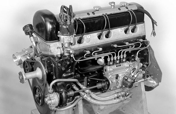
It is believed that for the first time this type of engine was used by Mitsubishi, but this is not entirely true. The first engine of this type was installed in the Mercedes-Benz W196 racing car. Later, Mitsubishi used an electronically controlled injection system, which allowed the engine to operate (at low loads) on an air-fuel mixture with a minimum amount of fuel, that is, lean.
The first Mitsubishi cars with GDI engines began to be produced in 1996. Since then, the engine has undergone many changes and improvements, as the original version was far from perfect.
As for the abbreviation GDI, it refers to Mitsubishi cars, although many automakers use the same system, but under a different name. Toyota has D4, Mercedes has CGI, Renault has IDE, etc.
The peculiarity of the engine is that at low loads (uniform driving at speeds up to 120 km / h) it runs on a lean air-fuel mixture. When the load increases, there is an automatic transition to the classic injection system. This makes the car economical (up to 20% savings) and environmentally friendly.
Operating principle

The general principle of operation of an internal combustion engine is to supply and mix fuel with air mass, since ignition is impossible without the latter. In gasoline engines, 14.7 g of air mixture per 1 g of gasoline is required for optimal operation. If the air is more than normal, such an air-fuel mixture is called lean (poor), if less - rich.
A lean air mixture reduces fuel consumption, but ignition is often a problem. An overly saturated mixture of gasoline ignites easily, but excess fuel does not burn and is removed along with the processed gases, which leads to useless waste. Not to mention the fact that a layer of soot is intensively formed on the candles and valves.
The GDI system differs from the usual one in that fuel is injected not into the intake manifold, but directly into the combustion chamber, like in engines running on diesel fuel.
The principle of operation of the GDI engine:
- Gasoline is fed into the combustion chamber under high pressure and swirling flow, thanks to the special structure of the nozzles.
- The flow at high speed collides with the piston, after which part of it is, as it were, fixed on the body of the piston, and the other part continues to move, creating friction and acquiring the appropriate shape.
- After that, the flow bends and moves away from the piston, increasing speed. Some particles move slowly and go in different directions, creating a flow separation.
- As a result of this, two sections with a gasoline-air mixture are formed in the combustion chamber. In the center is a section of a stoichiometric (ordinary) flammable fuel mixture. A lean mixture area forms around it.
- After that, ignition (with the help of a spark of spark plugs) of the area with a high content of gasoline occurs. Then the combustion process is transferred to the depleted areas.
The main differences between GDI and a conventional injection system

- The injection is carried out under pressure from 50 atmospheres (in a conventional injection engine, only 3 atm). This makes it possible to carry out finely dispersed directional spraying.
- The throttle valve is located slightly further than conventional motors.
- The fuel is fed directly into the cylinder and there the air-fuel mixture is formed. In conventional engines, fuel is fed into the intake manifold, where it mixes with the air mass.
- The pistons have a spherical recess. With the help of this recess, the formation of a vortex and the resulting flame are controlled. The recess also makes it possible to control the formation of a combustible mixture by adjusting the amount of air mass and gasoline in the connection process.
- There is a possibility of the formation of the most depleted combustible mixture in the cylinders. The optimal ratio of air to gasoline is 40:1 (as opposed to conventional injection with a ratio of 14.7:1), but the amount of air can range from 37 to 43 to 1.
- The nozzles located in the cylinder head have a configuration that allows you to give the fuel flow the desired, as if twisted, shape. Thanks to this, the flow moves along a clearly defined trajectory.
- GDI motors operate in two modes: STICH (ordinary, like other injection systems) and Compression on Lean (working at the most lean mixture). Switching between modes occurs automatically; when the load increases, the car switches to work with a rich fuel mixture. When the load decreases, it goes back to lean.
- The design is equipped with a high pressure pump.
Features of injection pump

The high pressure fuel pump (TNVD) is a key element of the direct injection system. The quality and performance of the motor as a whole depends on it.
There are four types of injection pumps:
1 generation. Seven plunger fuel pumps
The first and most short-lived. Installed in Mitsubishi cars from 1996 to 1998. They do not have a pressure monitoring system and are extremely sensitive to the quality of gasoline. They cannot be repaired, and when worn (and this happens very quickly), a complete replacement is necessary.
2 generation. Three-section fuel pumps
They are a modification of the seven-plunger. Installed from 1998 to 2000. Here the manufacturer took into account past shortcomings and paid attention to their elimination. They have a regulator and a pressure sensor, in case of a sharp drop, they put the car into emergency mode. This allows the vehicle to continue driving long enough to reach the service station.
The model has become somewhat more "loyal" to the quality of gasoline and more durable.
3rd generation. Two-section injection pump
There is a pressure sensor, but the regulator is not built into the system. The drive is powered by a camshaft.
4th generation. "Tablet"
The latest and most advanced model. Relatively durable, less sensitive to fuel quality, compact and reliable. The main disadvantage is self-loosening fixing nuts. Their condition must be checked regularly, as their weakening leads to a malfunction of the system and deformation of the plates, which are quite difficult to align.
The design of high pressure fuel pumps depends on the specific model.
How important is fuel quality?

The main problem of GDI engines is sensitivity to the slightest deviations in fuel quality. The first high-pressure fuel pumps suffered from this disease especially acutely, which led to very rapid wear and the need to replace them. Subsequent improvements partially or completely solved this problem and models of 2-4 generations became more reliable.
In addition to the features of the injection system itself, a thorough filtration system also affects the durability of the engine. It has 4 stages:
- Cleaning takes place using a mesh filter in the gas tank pump.
- It is cleaned with an ordinary filter. Depending on the brand of the car, its location may vary. The filter can be installed in the tank or under the bottom.
- Filtration takes place with the help of a filter cup located in the injection pump fuel line.
- The last stage of cleaning occurs at the moment when fuel is supplied from the "fuel rail" to the tank.
For example, the diaphragm valve and plungers are made with a high degree of precision, due to which the fuel mixture is injected at the required pressure. If gasoline is found to contain sand particles or other impurities, especially those with abrasive properties, the supply system will be affected by them and its operation will lose accuracy. Which will lead first to a decrease in the efficiency of the engine, and then to a breakdown of the high-pressure fuel pump.
First of all, when a problem occurs, engine power is reduced. After a while, he starts to refuse altogether. If you contact the repair shop at the first sign of a malfunction, the fuel pump can still be saved. Otherwise, it will have to be completely replaced, since it is pointless to restore badly damaged parts.
Another common GDI problem is floating speed. The reason can be both the impact of low-grade fuel and the natural wear of the high-pressure fuel pump elements.
When the pressure drops, the system automatically switches to the "classic" mode. After that, the pressure equalizes and the engine is switched back to the lean-burn mode, after which the pressure drops again, the system again switches to “classic” operation. And so on ad infinitum.
In the process of these transitions, the machine begins to “float”. If such a deviation is detected, the car should be sent for diagnostics in order to find the exact cause of the problem.
Conclusion
GDI engines are powerful and economical, but the good is almost always the cause of the bad. In this case, it is excessive sensitivity to the slightest deviations in the injection system and fuel quality. To extend the life of the car, you should regularly replace the spark plugs (soot quickly forms on them), clean the intake manifold and nozzles.
It will not be superfluous to regularly inspect the injector and check the quality of the spray, eliminating the slightest problems at the stage of their occurrence. And, of course, it is necessary to constantly monitor the condition of the filters and change as needed.
Video about modern injection engines:
Let's talk about the "new word in engine building" - the engine that received the abbreviation GDI (Gasoline Direct Injection), which can be translated as "engine with direct fuel injection", that is, the fuel on such an engine is not injected into the intake manifold, as on all other engines but directly into the engine cylinders. At the moment, cars with GDI system engines are manufactured by Mitsubishi (6G74, 4G93, 4G-73), Toyota (3S-FSE, 1AZ-FSE), Nissan (3.0-liter Engines VG30dd), BOSCH (Moronic MED7 system).
Let's dwell on some practical recommendations for GDI owners.
The first, main and most important thing that owners of such cars should understand for themselves is the quality of the fuel that you will fill in the fuel tank. It should be "the most-most": high-octane and clean (really high-octane and really clean). Naturally, the use of LEADED gasoline is absolutely not allowed. Also, do not abuse various kinds of "additives and cleaners", "octane boosters" and so on and so forth, which are in abundance in dozens of car dealerships.
And the reason for this ban is the very principles of "building" high-pressure fuel pumps, that is, the principles of "compressing and pumping fuel." For example, on the 6G74 GDI engine, a diaphragm-type valve is involved in this, and on the 4G94GDI engine, as many as SEVEN small plungers located in a special "cage" similar to a revolver and working according to a complex mechanical principle.
Both the diaphragm type valve and the plunger are high precision parts and their surfaces are finished with a cleanliness of at least grade 14. Naturally, if there are foreign impurities in the fuel or, God forbid, "ordinary" dirt, then it goes without saying that after some time of operation, the high-pressure fuel pump will simply "sit down", that is, it will no longer pump fuel into swirl nozzles with the desired pressure. Of course, the designers provide for fuel purification, which has several stages:
- The first cleaning of the fuel is carried out by the "mesh" of the fuel receiver of the fuel pump, located directly in the fuel tank.
- The second fuel purification is carried out by a "regular" fuel filter (on Mitsubishi it is located under the bottom of the car, on Toyota in the tank).
- The third fuel purification occurs when fuel enters the high-pressure fuel pump: at the "inlet" of the fuel line there is a "mesh - glass", 4 mm in diameter and 9 mm high.
- The fourth purification of the fuel is carried out when the fuel EXITS from the "fuel rail" back into the tank - structurally, the "exit" of the fuel is again carried out through the housing of the high-pressure fuel pump: there is the same "mesh-glass".
The first "bell" for the owner of the GDI engine that "something is wrong" with his engine is a decrease in power and throttle response, and if he does not pay attention to this, then further, after a while, the engine begins to refuse to start.
A necessary note: it is at this stage that the owner of the GDI engine needs to drop everything and "fly" to the service station that repairs such high pressure fuel pumps, because in this case something else can be corrected and at least a little, but restored.
Check and make sure the "guilt" in this high pressure fuel pump can be quite simple. To do this, you can apply a technique consisting of several "steps":
Step 1: "confirm or deny the guilt" of the electronic engine control system (all electronics), for which we carry out its diagnosis and reading the DTC.
Necessary note: The GDI high pressure fuel pump is a high precision mechanical precision device, and of all the "electronics" it has only a solenoid valve that "locks" the fuel. The self-diagnosis system on cars with GDI engines is really such an "advanced" system that sometimes it seemed to us that it was able to "think".
For example, the computer "knows" that the engine, after starting from a "cold" state, is not able to warm up in a couple of minutes (while conducting experiments, we forcibly changed the readings of the coolant temperature sensor immediately after starting the engine), and reacted to our actions with the "CHECK" light on the dashboard. The computer also "knows" how much "air is needed for normal engine operation", and when it decreases (we simulated the "clogged" air filter), it also lights up the "CHECK" light on the dashboard.
We conducted about thirty such tests and found out that the system is so "advanced" that it can command respect. However, despite its "advancement", the electronic system cannot, it simply is not "learned" to respond to changes in fuel pressure, due to the deterioration of the parameters of the "insides" of the high pressure fuel pump (wear due to the use of low-quality fuel). Therefore we do
Step 2: we check the health of the electromagnetic "locking" valve and if everything is fine here, then we do
Step 3: measure the pressure of the high pressure fuel pump at the "outlet". And knowing that it should be from 40 to 50 kgcm2, we look at the device and draw quite definite conclusions.
Cars with GDI engines are not yet "learned" to run on our fuel.
Well, if you still have a GDI engine and "nowhere to go", then the only thing that can be advised is to regularly, after several thousand kilometers, perform a complete cleaning of the high-pressure fuel pump in a specialized workshop.
Types of fuel injection GDI
Let's start with the fact that 4G93 engines are produced in two types: for "pure" Japan and for Europe. And they have differences and, one might say, quite thorough. And not only in the design of engines, high pressure fuel pump, but also in the fuel injection system itself. But in order to better and more correctly understand each other both now and in the future, it is necessary to agree on the accuracy of the wording, so that there would be no discrepancies or disagreements ...
So, let's begin. For "pure" Japan, there are only two types of fuel injection on GDI engines:
- operating mode on a super-lean fuel-air mixture (ULTRA LEAN COMBUSTION MODE)
- operation mode in the stoichiometric composition of the fuel-air mixture (SUPERIOR OUTPUT MODE)
For cars that are "Europeans", another mode has been added - TWO-STAGE fuel injection called: TWO-STAGE MIXING mode.
Switching operating modes
ULTPA LEAN COMBUSTION MODE - in this mode, the engine operates at speeds up to 115 - 125 km.h, provided that the acceleration is calm, soft and smooth, without sharp pressing the accelerator pedal. SUPERIOR OUTPUT MODE - this operating mode is activated at speeds over 125 km.h or if a large load "falls" on the engine (trailer, long climb uphill, and so on).
TWO-STAGE MIXING - a sharp start from a standstill or a sharp acceleration when overtaking.
Switching modes from one to another occurs automatically and almost imperceptibly for the driver, everything is controlled by the on-board computer.
ULTRA-LEAN COMBUSTION MODE
In this mode, the GDI engine runs on a super lean air/fuel ratio, approximately 37:1 to 43:1. The "ideal" ratio is 40:1. It is at this ratio that the fuel-air mixture burns out completely at speeds of calm movement of the car (without acceleration) up to 115-125 km / h and "gives out" the maximum torque to the engine. Fuel injection occurs on the compression stroke when the piston has not yet reached top dead center. The fuel is injected in a compact jet and, twisting clockwise, is mixed with air as completely as possible. The fuel injection time is from 0.3 to 0.8 ms (0.5 ms is taken as the ideal time).
This is a two-stage fuel injection mode, that is, fuel is injected into the cylinder twice in four strokes of the piston. Let's look at the picture:
During the first injection of fuel on the intake stroke, the air/fuel ratio is as low as 60:1. This is a "two times super-lean mixture" and in this ratio it will never ignite (not ignite) and serves mainly to cool the combustion chamber, because the lower its temperature is, the more will enter there on a cycle air intake and, therefore, the more fuel - respectively, you can apply there on the second cycle - the compression stroke (see figure). That is, all this was invented only in order to increase the filling factor of the combustion chamber (there is something to think about ... for example, about "black" GDI spark plugs - no matter how you look, they are "black and black". And practically - always and on all engines that come for diagnostics or repairs).
More specifically, on the compression stroke in the combustion chamber, the composition of the fuel-air mixture is equal to 12: 1 (super-enriched fuel-air mixture).
Fuel injection time: on the intake stroke - 0.5 - 0.8 ms; on the compression stroke - 1.5 - 2.0 ms
All this allows you to get maximum power, for comparison: at the same speed, for example, RPM 3000, the GDI engine "gives out" 10% more power than the same MPI (ported fuel injection).
It's only "the devil is terrible when he is painted", and the GDI injection pump device is quite simple. If you figure it out and have some desire, for example ... Let's look at the photo and see the disassembled single-section seven-plunger high-pressure pump GDI:

From left to right:
1-magnetic drive: drive shaft and splined shaft with magnetic spacer between them
2-Plunger Support Plate
3-cage with plungers
4-seat plunger cage
5-pressure chamber pressure reducing valve
6-valve adjustable high pressure outlet with injectors-fuel pressure regulator
7-spring damper
8-drum with plunger pressure chambers
9-washer-separator of low and high pressure chambers with refrigerators for gasoline lubrication
10-case injection pump with solenoid relief valve and port for pressure gauge
The order of assembly and disassembly of the injection pump is shown in the photo in numbers. We exclude only positions 5 and 6, because the valve data can be installed immediately during assembly, before the drum with plungers is installed. After assembling the pump, you should fix it and start turning the shaft to make sure that everything is assembled correctly and rotates without "wedges". This is the so-called simple "mechanical" check.
In order to carry out a "hydraulic" test, it is necessary to check the performance of the injection pump "for pressure".
Yes, the injection pump device is "quite simple", however ...
Many complaints from GDI owners, many! And the reason, as has been said many times "on the Internet", is only one - our native Russian fuel ... From which not only the spark plugs "blush" and with a decrease in temperature the car starts disgustingly (if it starts at all), but also the "swallow" with GDI, everything withers and withers with every liter of Russian fuel poured into it ...
Let's look at the photo and "point the finger" at everything that wears out in the first place and what you need to pay attention to first of all:
Cage with plungers and drum with injection chambers

photo 1 (complete)
If you look closely (take a closer look), you will immediately notice some "incomprehensible scuffs" on the drum body. What then happens inside?

photo 2 (separately)

photo 3 (drum with pressure chambers)
And here you can already clearly see - WHAT our Russian gasoline is ... the same reddishness, just rust on the plane of the drum. Naturally, she (rust), not only remains here, but also gets on the plunger itself and on everything "on which it rubs"
- look at the photo below...

photo 4
And in this picture it is clearly visible what "little troubles" our - native - gasoline can bring us. The arrows show "some abrasions", due to which the plunger (plungers) stop building up pressure and the engine starts to "work somehow wrong ...", as the owners of the GDI say.
To restore the GDI injection pump, it would be nice to have "some" spare parts.
Mitsubishi can be called a pioneer in the mass introduction of direct fuel injection. Unlike Mersedes, which long before Mitsubishi were trying to implement direct injection in cars, simply applying the best practices from experience in the aircraft industry, Mitsubishi engineers created a system that would be convenient and suitable for everyday car use. Consider the GDI engine, the device and the principle of operation of the power system.
Basic concepts
In the article about, we found out that there are several types of fuel injection systems:
- single point injection (monoinjector);
- distributed injection on valves (full injector);
- distributed injection into cylinders (direct injection).
Gasoline Direct Injection, which means direct gasoline injection, immediately tells us that internal mixture formation occurs in GDI engines. In other words, fuel is injected directly into the cylinders. But what exactly are the advantages of direct injection:
The problem of the low efficiency of a gasoline engine, compared to a diesel engine, is within a small framework of adjusting the composition of TPVS. Theoretically and experimentally, it was found that 14.7 kg of air is needed for complete combustion of 1 kg of gasoline. This ratio is called stoichiometric. The engine can run on a lean mixture - about 16.5 kg of air / 1 kg of gasoline, but already at 19/1 TPVS from the spark plug will not ignite. But even a 16.5/1 mixture is considered too lean for normal operation, since TPVS burns slowly, which is fraught with power loss, overheating of the piston rings and combustion chamber walls, and therefore the working lean homogeneous mixture lies within 15-16/1. By preparing a rich mixture in the cylinders with a ratio of 12.1-12.3 / 1 and shifting the UOZ, we get an increase in power, while the environmental performance of the motor is significantly deteriorating.
Economy of GDI
The problem with conventional engines with multiport valve injection is that fuel is supplied exclusively on the intake stroke. The mixing of fuel with air begins to occur even in the intake manifold, as a result, when the piston moves to TDC, the mixture becomes close to homogeneous, that is, homogeneous. The advantage of GDI is that the engine can run very lean when the fuel to air ratio can reach 37-41/1. 
- special intake manifold design;
- nozzles that allow not only to accurately dose the amount of fuel supplied, but also to adjust the shape of the torch;
- special shape pistons.
But what exactly is the peculiarity of the principle of operation that allows GDI motors to be so economical? The air flow, due to the special shape of the intake manifold, consisting of two channels, has a certain direction even at the intake stroke, and does not enter the cylinders randomly, as is the case with conventional engines. Getting into the cylinders and hitting the piston, it continues to twist, thereby contributing to turbulence. The fuel, which is supplied in the immediate vicinity of the piston to the TDC by a small torch, hits the piston and, picked up by the swirling air flow, moves in such a way that at the moment the spark is applied it is in close proximity to the spark plug electrodes. As a result, the normal ignition of the TPVS occurs near the candle, while in the surrounding cavity there is a mixture of clean air and exhaust gases supplied to the inlet by the EGR system. As you understand, it is not possible to implement such a method of gas exchange in a conventional engine. 
Engine operating modes
GDI motors can work effectively in several modes:
- Ultra-LeanCombustionMode- super-poor mixture mode, the flow principle of which was discussed above. It is used when there is no heavy load on the engine. For example, with smooth acceleration or constant maintenance of not too high speed;
- SuperiorOutputMode- a mode in which fuel is supplied during the intake stroke, which allows obtaining a homogeneous stoichiometric mixture with a ratio close to 14.7/1. Used when the engine is under load.
- Two-stagemixing- rich mixture mode, in which the ratio of air to fuel is close to 12/1. It is used at sharp accelerations, heavy load on the engine. This mode is also called the open loop mode (Open loop), when the lambda probe is not interrogated. In this mode, fuel trim to regulate emissions of harmful substances is not carried out, since the main goal is to get the most out of the engine.
The electronic engine control unit (ECU) is responsible for switching modes, which makes a choice based on the readings of sensor equipment (TPDZ, DPKV, DTOZH, lambda probe, etc.) 
Two-stage mixing
The dual-stage injection mode is also a feature that allows the GDI engines to be extremely responsive. As mentioned above, the composition of the mixture in this mode reaches 12/1. For a conventional engine with distributor injection, such a fuel-to-air ratio is too rich, and therefore such a TFA will not ignite and burn efficiently, and emissions of harmful substances into the atmosphere will significantly worsen.
Open loop mode involves 2 stages of fuel injection:
- a small portion on the intake stroke. The main purpose is to cool the gases remaining in the cylinder and the walls of the combustion chamber themselves (the composition of the mixture is close to 60/1). Subsequently, this allows more air to enter the cylinders and create favorable conditions for igniting the main portion of gasoline;
- main portion at the end of the compression stroke. Thanks to the favorable conditions created by the pre-injection and the turbulence in the combustion chamber, the resulting mixture burns extremely efficiently.
There is a great desire to talk about exactly how Mitsubishi engineers “tamed” turbulence, about laminar and turbulent motion and the Re number introduced by O. Reynolds. All this would help to better understand exactly how layer-by-layer mixture formation is created in GDI motors, but, unfortunately, two articles are not enough for this. 
injection pump
As with a diesel engine, a high pressure fuel pump is used to create sufficient pressure in the fuel rail. Over the years of production, the motors were equipped with high-pressure fuel pumps of several generations:

nozzles
To ensure high-precision control of the composition of TPVS, the nozzles must have extremely high accuracy. The very principle of opening the plunger for fuel supply is similar to a conventional electromagnetic nozzle. Features of the GDI system injectors:
- the possibility of forming different types of gasoline spray;
- maximum preservation of dosing accuracy regardless of temperature and pressure in the combustion chamber.
Particularly noteworthy is the swirl device located in the nozzle body. It is thanks to him that the fuel, flying out of the nozzle, is better picked up by the swirling air flow, which contributes to better mixing of the TPVS and redirecting the mixture to the spark plug. 

Exploitation
The main troubles associated with the operation of direct injection engines from Mitsubishi in domestic open spaces:
- TNDV wear. The pump is an assembly with pretentious requirements for fitting parts, and the main problem is not the level of manufacture, but the quality of domestic fuel. Of course, even now you can run into bad fuel. But the days when the quality of gasoline was a real headache and the risk of financial loss for owners of cars with GDI engines, fortunately, have already passed;
blockage of air passages in the intake manifold. The formation of build-ups corrects the movement of air masses and the process of mixing fuel with air. This is what is called one of the reasons for the formation of black soot on spark plugs, which is so well known to owners of cars with GDI engines.