At the end of the last century, Japanese automakers created many sports engines, which, due to performance, potential and reliability, are considered to be the best to this day. Next, one of them is considered - 2JZ-GTE. Characteristics, design, operation and tuning features are described below.
Story
The JZ engine series replaced the M series in 1990. The power units in question went through two generations during production (in 1996). In 2007 they were replaced by the V-shaped GR series.
As for the 2JZ-GTE, it was produced from 1991 to 2002.
General Features
Toyota's JZ engine series includes two lines: 1JZ and 2JZ. The main difference between them is the volume and design of the cylinder block. Both lines of engines have a six-cylinder in-line configuration. Equipped with a DOCH gas distribution mechanism with 4 valves per cylinder. Designed for use with rear-wheel drive or all-wheel drive transmission and longitudinal arrangement.
The turbocharged version was developed as an analogue of the Nissan RB26DETT sports engine, which appeared two years earlier than the 2JZ-GTE. Its characteristics are very close, the layout is the same.
Design
JZ motors have two camshafts, 4 valves per cylinder, timing belt drive, ACIS variable geometry intake manifold. There are no hydraulic lifters. 2JZ differs from 1JZ in a large volume (3 liters instead of 2.5). Both variants have a cast-iron cylinder block, but the 2JZ has it 14mm higher. In addition, in the engine under consideration, unlike the 1JZ, the cylinder diameter and piston stroke are equal and amount to 86 mm. Aluminum cylinder head.
After modernization, both lines of the JZ series were equipped with a variable valve timing system VVT-i.
The 2JZ line included three versions: GE, FSE, GTE. The first is the basic atmospheric option. The second differs from it by the presence of direct injection. The third modification is equipped with a turbocharger.
The 2JZ-GTE has two Hitachi CT20A turbochargers and an intercooler. In addition, they used connecting rods from the GE version, pistons designed for a compression ratio of 8.5, with recesses and additional oil grooves. The camshaft lift is 7.8 / 8.4 mm, the phase is 224/236. Nozzles - 430 cc.
Engines for the foreign market were equipped with CT12B turbines with stainless steel parts instead of ceramic parts, 8.25 / 8.4 mm lift camshafts and phase 233/236, 540 cc injectors.
The principle of operation of supercharging is noteworthy, combining the bi- and twin-turbo schemes: one turbine starts working from 1800 rpm, the second one is connected from 4000 rpm.
Performance
The most powerful version of the 2JZ is naturally the turbocharged 2JZ-GTE. Its characteristics initially amounted to 276 liters. With. power at 5600 rpm and 435 Nm of torque at 4000 rpm. This is due to legal requirements.
Due to the slightly modified design of the 2JZ-GTE export variants, their characteristics were higher. Power was 321 liters. With. at 5600 rpm, torque - 441 Nm at 4800 rpm.
During the modernization, as mentioned, the engine was equipped with a variable valve timing system. Thus, the 2JZ-GTE VVTi was born. Its technical characteristics have increased compared to the original version. So, the torque increased to 451 Nm.

Application
2JZ-GTE was used on only two Toyota models. This is Aristo in both generations (JZS147 and JZS161) and Supra (JZA80). On Aristo, it was equipped exclusively with a 4-speed automatic. On the Supra, in addition to it, they offered a 6-speed manual transmission.
Operation features
The engine resource is more than 500 thousand km. It is recommended to fill it with 95 gasoline and use 5W-30 oil. The motor holds 5.5 liters of it, the consumption is up to 1000 g per 1000 km. The recommended replacement interval is once every 10,000 km, although it is desirable to carry out this procedure twice as often. The operating temperature is 90 ° C. The service life of the timing belt is 100 thousand km. The valves are adjusted with washers at the same frequency.
Problems
The most problematic part of the engine is the variable valve timing system. Many malfunctions are associated specifically with VVT-i: tripling and floating speed (valve), knocking (clutch). In addition, you need to be very careful when washing, since it is easy to fill in candles, as a result of which the engine may not start and triple. In addition, tripping can be caused by faulty coils. A clogged throttle and an idle speed sensor or valve lead to rev instability. The main reason for increased fuel consumption is a faulty oxygen sensor, filters, DMRV. Extraneous sounds (knocking) can be caused by unadjusted valves, connecting rod bearings, belt tensioner bearing of mounted units. To get rid of excessive oil consumption, valve stem seals and rings are changed. The pump has a short lifespan.
The main problematic parts are the timing tensioner bracket, crankshaft pulley, oil pump seal. In addition, note the poor purge of the cylinder head. Possible boost failure.
tuning
The engine in question has a very great potential for tuning. Therefore, it is one of the most frequently modified motors. The high potential is primarily due to the large margin of safety of the 2JZ-GTE. Technical characteristics can be increased by one and a half times without loss of resource and without serious intervention in the design.

In addition, the engine itself is often a tuning element: 2JZ-GTE is one of the most commonly used engines for swapping.
The 1JZ-GE engine can be safely called a legend created by the designers of the Japanese company Toyota. Why a legend? The 1JZ-GE was the first engine in the new JZ range created in 1990. Now the engines of this line are actively used in motorsport and in ordinary cars. 1JZ-GE became the embodiment of the latest technologies of that time, which are still relevant today. The engine has established itself as a reliable, easy to operate and relatively powerful unit.
Characteristics 1JZ-GE
| Number of cylinders | 6 |
| Cylinder arrangement | in-line, longitudinal |
| Number of valves | 24 (4 per cylinder) |
| Type of | petrol, injection |
| Working volume | 2492 cm3 |
| Piston diameter | 86 mm |
| piston stroke | 71.5 mm |
| Compression ratio | 10:1 |
| Power | 200 HP (6000 rpm) |
| Torque | 250 Nm (4000 rpm) |
| Ignition system | distributor |
First and second generation
ATTENTION! Found a completely simple way to reduce fuel consumption! Don't believe? An auto mechanic with 15 years of experience also did not believe until he tried it. And now he saves 35,000 rubles a year on gasoline!
As you can see, the toyota 1JZ-GE is not turbocharged and the first generation had distributor ignition. The second generation was equipped with coil ignition, 1 coil was installed for 2 candles, and a VVT-i valve timing system.

1JZ-GE in Toyota Chaser
1JZ-GE vvti - the second generation with variable valve timing. Variable phases allowed to increase power by 20 horsepower, smooth out the torque curve, and reduce the amount of exhaust gases. The mechanism works quite simply, at low speeds the intake valves open later and there is no valve overlap, the engine runs smoothly and quietly. At medium speeds, valve overlap is used to reduce fuel consumption without losing power. At high RPMs, VVT-i maximizes cylinder filling to increase power.
The first generation engines were produced from 1990 to 1996, the second generation from 1996 to 2007, they were all equipped with four and five-speed automatic transmissions. Installed on:
- Mark II Blit;
- Chaser;
- Cresta;
- progress;
- Crown.
Operation and repair
JZ series engines work normally on 92nd and 95th gasoline. On the 98th, it starts worse, but has high productivity. Two are present. The crankshaft position sensor is located inside the distributor, there is no starting nozzle. Platinum spark plugs need to be changed every 100,000 miles, but to replace them you will have to remove the top of the intake manifold. The volume of engine oil is about five liters, the volume of coolant is about eight liters. Vacuum air flow meter. To, which is located near the exhaust manifold, can be reached from the engine compartment. The radiator is normally cooled by a fan attached to the water pump shaft.
Overhaul of 1JZ-GE may be needed after 300 - 350 thousand kilometers. Naturally standard preventive maintenance and replacement of consumables. Probably the sore point of the engines is the timing belt tensioner, which is only one and often breaks. Problems can also arise with the oil pump, if it is simple, then it is similar to the VAZ one. Fuel consumption with moderate driving from 11 liters per hundred kilometers.
1JZ-GE in JDM culture
JDM stands for Japanese Domestic Market or Japanese Domestic Market. This abbreviation formed the basis of a worldwide movement, which was initiated by the JZ series engines. Nowadays, probably, most of the engines of the 90s are installed in drift cars, as they have a huge supply of power, are easily tuned, simple and reliable. This is confirmation that the 1jz-ge is a really good engine, for which you can safely give money and are not afraid that you will stop at the side of the road on a long journey ...
The Toyota JZGE engine line is a series of gasoline inline six-cylinder automotive engines that replaced the M line. All engines in the series have a DOHC gas distribution mechanism with 4 valves per cylinder, engine displacement: 2.5 and 3 liters.
Engines are designed for longitudinal placement for use with rear-wheel drive or all-wheel drive transmission. Produced from 1990-2007. The GR line of V6 engines became the successor. The 2.5 liter 1JZ-GE was the first engine in the JZ line. This engine was equipped with a 4 or 5-speed automatic transmission. The first generation (until 1996) had a classic "distributor" ignition, the second - "coil" (one coil for two spark plugs). In addition, the second generation was equipped with a variable valve timing system VVT-i, which allowed to smooth the torque curve and increase power by 14 hp. With. Like the rest of the engines in the series, the timing mechanism is driven by a belt, the engine also has only one drive belt for attachments. When the timing belt breaks, the engine is not destroyed. The engine was installed on cars: Toyota Chaser, Cresta, Mark II, Progres, Crown, Crown Estate, Blit.


Specifications 1JZ-GE, 1st and (2nd) generation:
Type: Petrol, injection Volume: 2 491 cm3
Maximum power: 180 (200) hp, at 6000 (6000) rpm
Maximum torque: 235 (255) N m, at 4800 (4000) rpm
Cylinders: 6. Valves: 24. Piston diameter 86 mm, piston stroke - 71.5 mm.
The compression ratio is 10 (10.5).
Operating conditions, thin spots in repair, engine problems 1JZ-GE 2JZ-GE.
Diagnostics: Date from the scanner.
The developers have laid down a fairly informative diagnostic date, according to which it is possible to accurately analyze the operation of the sensors using the scanner. Laid the necessary tests of the sensors. The exception is the ignition system, which is practically not diagnosed by the scanner. The date presents the operation of all sensors and electronic components without frills. In graphical mode, viewing the switching of the oxygen sensor is informative. There are tests for checking the fuel pump, changing the injection time (the duration of the opening of the injectors), activating the VVT-i, EVAP, VSV, IAC valves. The only negative, there is no test - a power balance with alternately turning off the injectors, but this flaw can be easily bypassed by disconnecting the connectors from the injectors to determine an idle cylinder. In general, most problems are recognized during scanning, without the use of additional equipment. The main thing is that the scanner is checked and with the correct display of parameters and symbols.
Below are screenshots from the scanner display.
A photo. Unreal oxygen sensor data (short circuit of the signal circuit to the heating circuit).

Photo.Scanner software error

Photo. A window with a list of tests for activation of executive bodies.

Photo. Continued

Photo. Display of current oxygen sensor data in graphical mode.

A photo. A fragment of the current data from the scanner.

Sensors engine 1JZ-GE 2JZ-GE.
Knock sensor.
The knock sensor detects detonation in the cylinders and transmits information to the control unit. The unit corrects the ignition timing. If the sensors (there are two of them) malfunction, the unit fixes error 52.54 P0325, P0330.
As a rule, the error is fixed after a “strong” re-gassing on x \ x or when moving. It is impossible to check the sensor performance on the scanner. You need an oscilloscope to visually monitor the signal from the sensor. Photo. Sensor location. The stuffing of the sensor.


Oxygen sensor(s).
The problem of the oxygen sensor (s) on this motor is standard. Breakage of the sensor heater and contamination of the active layer with combustion products (decrease in sensitivity). Repeatedly there were cases of breakage of the active element of the sensor. Sensor examples.


In the event of a sensor malfunction, the unit fixes error 21 P0130, P0135. P0150, P0155. You can check the performance of the sensor on the scanner in graphical viewing mode or using an oscilloscope. The heater is physically checked by a tester - resistance measurement.
Rice. An example of the operation of an oxygen sensor in graphical viewing mode.

Rice. Error codes fixed by the scanner.
Temperature sensor.
The temperature sensor registers the motor temperature for the control unit. In the event of an open or short circuit, the control unit fixes error 22, P0115.
A photo. Temperature sensor readings on the scanner.

A photo. Temperature sensor, and its location on the motor block.


A typical sensor failure is incorrect data. That is, as an example, on a hot motor (80-90 degrees), the sensor readings of a cold motor (0-10 degrees). At the same time, the injection time is greatly increased, a black soot exhaust appears, and the stability of the engine at idle is lost. And starting a hot engine becomes very difficult and long. Such a malfunction is easy to fix on the scanner - the temperature readings of the motor will randomly change from real to minus. Replacing the sensor is somewhat difficult (difficult to access), but with the right approach and the use of special. tool is easy to do. (On a cold engine).
VVT-i valve.
The VVT-i valve causes a lot of problems for owners. Rubber rings, in its design, are compressed into a triangle over time and press the valve stem. The valve wedges - the stem gets stuck in an arbitrary position. All this leads to the passage of oil (pressure) into the VVT-i clutch. The clutch turns the camshaft. At the same time, at idle, the engine starts to stall. Either the revs become very high, or they float. Depending on the malfunction, the system fixes errors 18, P1346 (a violation of the timing phases is detected within 5 seconds); 59, P1349 (At a speed of 500-4000 rpm and a coolant temperature of 80-110 °, the valve timing differs from the required ± 5 ° for 5 or more seconds); 39, P1656 (valve - open or short circuit in the valve circuit of the VVT-i system for 1 or more seconds).

Below in the photographs is the valve installation location, catalog number, valve disassembly and examples of “triangular” rubber rings, the date with a changed vacuum due to the valve wedge. Example of a stuck valve stem and oil filter location.


The system test consists of testing the operation of the valve. The scanner provides a test - the inclusion of the valve. When the valve is turned on at idle, the engine stalls. The valve itself is physically checked for stem travel sticking. Replacing the valve is not particularly difficult. After replacement, you need to reset the battery terminal to bring the speed back to normal. Valve repair is also possible. You need to flare it and replace the o-ring. The main thing during the repair is to observe the correct position of the valve stem. Before repair, it is necessary to make control marks for installing the core, relative to the winding. You also need to clean the filter mesh in the VVT-i system.
crankshaft sensor.
Conventional inductive sensor. Generates impulses. Fixes the speed of the crankshaft. The oscillogram of the sensor has the following form.

The photo shows the location of the sensor on the motor and a general view of the sensor.


The sensor is quite reliable. But in practice, there have been cases of interturn short circuit of the winding, which led to the disruption of generation at certain speeds. This provoked a speed limit during throttling - a kind of cut-off. A typical malfunction associated with the breaking off of the marker teeth of the gear (when replacing the crankshaft oil seal and dismantling the gear). Mechanics during disassembly forget to unscrew the gear stopper.

In this case, starting the engine becomes either impossible, or the engine starts, but there is no idling - and the engine stalls. If the sensor breaks (no readings), the motor does not start. The block fixes error 12,13, P0335.
Camshaft sensor.
The sensor is installed on the head of the block, in the region of the 6th cylinder.


An inductive sensor generates pulses - it counts the speed of rotation of the camshaft. The sensor is also reliable. But there were sensors, through the body of which engine oil flowed, and the contacts were oxidized. There were no breaks in the sensor winding in my practice. But the occurrence of an error on the inoperability of the sensor - when the belt jumped (out of synchronization), there was plenty.

Therefore, if error P340 occurs, it is necessary to check the correct installation of the timing belt.
MAP manifold absolute pressure sensor.
The intake manifold absolute pressure sensor is the main sensor, according to which the fuel supply is formed. The injection time directly depends on the sensor readings. If the sensor is faulty, then the unit fixes error 31, P0105.

As a rule, the cause of the malfunction is a human factor. Either a tube that has flown off the sensor fitting, or a broken wire or a connector that is not fixed until it clicks. The performance of the sensor is checked according to the readings on the scanner - a line indicating the absolute pressure. According to this parameter, abnormal suction in the intake is easily fixed. Or, together with other codes, the operation of the VVT-i system is evaluated.
Idle stepper motor.
On the first motors, a stepper motor was used to control the load speed, warm-up and idle.


The motor was very reliable. The only problem is the contamination of the motor rod, which led to a decrease in idle speed and engine stops, under load - or at traffic lights. The repair consisted in dismantling the motor from the throttle body, and cleaning the stem and body from deposits. Also, when removing, the motor sealing ring is changed. The dismantling of the stepper motor was possible only with the partial removal of the throttle body.
IAC valve.
On the next generation of motors, a solenoid valve (idling valve IAC) was used to control the speed. There were many more problems with the valve. It often got dirty and wedged.


Rice. control impulses.

At the same time, the engine speed became either very high (remained warm) or very low. The decrease in speed was accompanied by a strong vibration when the loads were turned on. You can check the operation of the valve using a test on the scanner. It is possible to programmatically open or close the valve shutter and observe the change in speed. Control pulses must be checked before dismantling.


If the speed does not change on the test, the valve is cleaned. Disassembly of the valve presents a certain difficulty. The bolts that fix the winding are unscrewed with a special tool. Five pointed star.


Repair consists in flushing the valve shutter (elimination of jamming). But there are pitfalls here. With abundant flushing, the grease is washed out of the rod bearings. This leads to re-jamming. In such a situation, repair is possible only by relubricating the bearings. (Lowering the valve body into hot oil and then removing excess lubricant when cooling down) If there are problems with the electronic winding of the valve, the control unit fixes error 33; P0505.
Repair consists in replacing the winding. You can change the speed a little by adjusting the position of the winding in the housing. After any manipulations with the valve, it is necessary to reset the battery terminal.
Throttle position sensor has been installed on all kinds of engines. In the first version, when replacing it, it required the adjustment of the idling sign. In the second installation was carried out without adjustments. And on the electronic damper, a special adjustment of the sensor was required.


If the sensor malfunctions, the unit fixes error 41 (P0120).
The correct operation of the sensor is controlled by the scanner. On the adequacy of switching the sign of idling and in the graph the correct change in voltage during throttling (without dips and surges in voltage). The photo shows a fragment of the date from the engine scanner with an idle valve. Sensor reading at idle 12.8%

When the sensor breaks, a chaotic speed limit is observed, incorrect automatic transmission switching. And on a motor with el. damper – complete shutdown of damper control. Replacing the sensor is not difficult. On the first engines, the replacement includes the correct installation and adjustment of the idle sign. On the second type of motors, the replacement consists in the correct installation and reset of the battery. And on email. throttle adjustment is carried out using a scanner. You need to turn on the ignition, turn off the email. damper motor, press the damper with your finger and set the TPS readings on the scanner to 10% -12%. Then connect the motor connector and reset the errors. After start the engine and check the sensor readings. At idle, the warm engine readings should be in the region of 14-15%.
The photo shows the correct readings of the sensor on the electric throttle in idle mode.

Installed on systems with email. throttle. In the event of a malfunction, the unit fixes the error P1120, P1121. When replacing does not require adjustment. It is checked by a scanner and physically measuring the resistance of the channels.


Electronic choke.
The idle valve and cable-actuated mechanical throttle were replaced by an electronic throttle in the 2000s. Completely reliable robot design.

The gas cable was left in order to be able to control the damper in the event of a malfunction (it allows you to slightly open the damper with the gas pedal almost completely pressed). The gas and throttle pedal position sensors and the motor are mounted on the damper body. This gives an advantage in repair. Problems with the electronic throttle are associated with the failure of sensors. On average, after 10 years of operation, the active resistive layer on potentiometers is erased. The repair consists in replacing the sensors, setting the TPS and then resetting the control unit.
Gas distribution engine 1JZ-GE 2JZ-GE.
The timing belt is changed every 100 thousand mileage. Timing belt and installations are checked during diagnostics. Initially, they check the absence of codes on the camshaft, then the ignition angle with a stroboscope.

And if there are prerequisites, they check the marks, physically combining them, or with an oscilloscope to view the synchronization of the crankshaft and camshaft sensors.

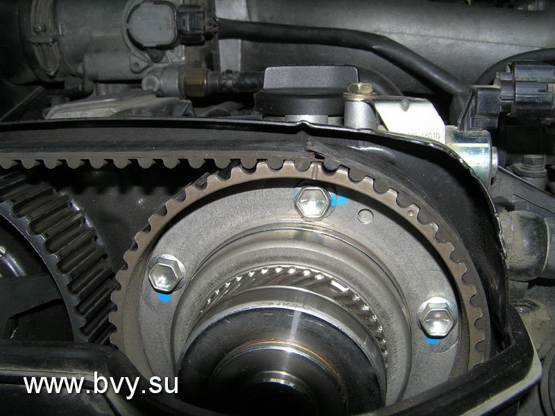
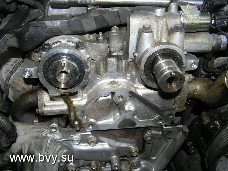
Belt change on 1JZ-GE 2JZ-GE motors is carried out in conjunction with roller seals and a hydraulic tensioner. On the top cover there is a photo of the correct removal of the VVT-I coupling. Clearly defined alignment marks on the belt and on the gears leave little chance of incorrect installation of the belt. When the timing belt breaks, there is no fatal meeting of the valves with the piston. Below in the photographs are examples of belt wear, timing belt number, removed gears, alignment marks and hydraulic tensioner.


Ignition system engine 1JZ-GE 2JZ-GE.
Distributor.
The distributor - standard execution. Inside are position and speed sensors and a slider.


Contacts of high-voltage wires in the cover are numbered. The first cylinder is marked for installation. The only inconvenience is the installation of the distributor in the head. The drive is gear, but it also has marks for proper installation. Distributor problems are usually related to oil leakage. Either through the outer ring, or through the stuffing box inside. The outer rubber ring changes quickly without problems, but replacing the oil seal causes certain difficulties. Hot fit marker gear - the process of replacing the oil seal nullifies. But with a competent approach and skillful hands, this problem can be solved. The size of the gland is 10x20x6. The electrical problems of the distributor are standard - wear or sticking of the coal in the cover, contamination of the contacts of the cover and the slider and an increase in gaps due to burnout of the contacts.
Ignition coil and switch, high voltage wires.


The remote coil practically did not fail, worked flawlessly. An exception is the filling with water when washing the motor, or a breakdown of the insulation during operation with broken high-voltage wires. The switch is also reliable. It has a CIP design and reliable cooling. Contacts are signed for quick diagnostics. High-voltage wires are the weak link in this system. With an increase in the gaps in the candles, a breakdown occurs in the rubber tip of the wire (strip), which leads to the “triple” of the motor. It is important during operation to carry out a scheduled replacement of candles by mileage. Structurally, the wire of the 6th cylinder is subject to water ingress. This also leads to breakdowns. The 4th cylinder is completely inaccessible for diagnostics and inspection. Access is only possible by removing part of the intake manifold. The 3rd cylinder is subject to antifreeze ingress when dismantling the damper body - this should be taken into account during repairs. The operation of the ignition system is affected by oil leakage from under the valve covers. Oil destroys the rubber lugs of high voltage wires. Restyled engines were equipped with a DIS ignition system (one coil for two cylinders) without a distributor. With remote switch and crankshaft and camshaft sensors.


The main failures are the breakdown of the rubber tips of the coils and wires, when the spark plugs are worn out, the vulnerability of the 6th and 3rd cylinders, and the ingress of water, oil and dirt during the general aging of the engine. During winter bays, cases of destruction of coil and wire connectors are not uncommon. Difficult access to the middle cylinders makes owners forget about their existence. Proper maintenance and seasonal diagnostics completely remove all these problems and troubles.
Fuel system Filter, injectors, fuel pressure regulator.
The average fuel pressure required for engine operation is 2.7-3.2 kg / cm3. When the pressure drops to 2.0 kg, there are dips during regassing, power limitation, backache in the intake. It is convenient to measure the pressure at the inlet to the fuel rail by first unscrewing the damper. It is also convenient to connect here for flushing the fuel system.

The fuel filter is installed under the bottom of the car. The replacement cycle is 20-25 thousand kilometers. Replacement presents a certain difficulty. It is necessary that the tank be almost empty when replacing. Fitting on the tubes to the filter with a peculiar profile. They are unscrewed with great effort (to prevent fuel leakage). On a car since 2001, the filter has been moved to the fuel tank and its replacement is not difficult. The fuel rail with injectors is located in an easily accessible place. The injectors are very reliable, easy to clean - when flushing the fuel system. Checking the operation of the injectors is carried out with an oscilloscope. When the internal resistance of the winding changes, the shape of the pulse changes. You can also check the operation of the injector and its relative "clogging" by measuring the current (current clamps). For changes in current. The winding resistance is measured with a tester. The spray of the injector is checked on the stand - by visual inspection of the spray cone and the amount of filling for a certain time.
The photo shows the correct impulse.

Water ingress is detrimental to the injector. Since the date does not provide for a cylinder performance test, it is possible to determine an idle or inefficient cylinder by turning off the corresponding injector. The injectors are flushed according to diagnostic readings. Reason for flushing Lean mixture errors 25 (P0171), or gas analyzer reading - a large amount of oxygen in the exhaust. The fuel pressure regulator is mounted on the fuel rail. It is adjusted to release pressure in the return line above 3.2 kg. The mechanism breaks when exposed to water. I haven't had any other problems with it in my experience. The fuel pump is installed in the tank. Standard pump. Its performance is evaluated by measuring the pressure (with the vacuum tube removed from the pressure regulator). When the operating pressure drops to 2.0 kg, the engine loses power.
The Toyota JZGE engine line is a series of gasoline inline six-cylinder automotive engines that replaced the M line. All engines in the series have a DOHC gas distribution mechanism with 4 valves per cylinder, engine displacement: 2.5 and 3 liters.
Engines are designed for longitudinal placement for use with rear-wheel drive or all-wheel drive transmission. Produced from 1990-2007. The GR line of V6 engines became the successor. The 2.5 liter 1JZ-GE was the first engine in the JZ line. This engine was equipped with a 4 or 5-speed automatic transmission. The first generation (until 1996) had a classic "distributor" ignition, the second - "coil" (one coil for two spark plugs). In addition, the second generation was equipped with a variable valve timing system VVT-i, which allowed to smooth the torque curve and increase power by 14 hp. With. Like the rest of the engines in the series, the timing mechanism is driven by a belt, the engine also has only one drive belt for attachments. When the timing belt breaks, the engine is not destroyed. The engine was installed on cars: Toyota Chaser, Cresta, Mark II, Progres, Crown, Crown Estate, Blit.
Specifications 1JZ-GE, 1st and (2nd) generation:
Type: Petrol, injection Volume: 2 491 cm3
Maximum power: 180 (200) hp, at 6000 (6000) rpm
Maximum torque: 235 (255) N m, at 4800 (4000) rpm
Cylinders: 6. Valves: 24. Piston diameter 86 mm, piston stroke - 71.5 mm.
The compression ratio is 10 (10.5).
Operating conditions, thin spots in repair, engine problems 1JZ-GE 2JZ-GE.
Diagnostics: Date from the scanner.
The developers have laid down a fairly informative diagnostic date, according to which it is possible to accurately analyze the operation of the sensors using the scanner. Laid the necessary tests of the sensors. The exception is the ignition system, which is practically not diagnosed by the scanner. The date presents the operation of all sensors and electronic components without frills. In graphical mode, viewing the switching of the oxygen sensor is informative. There are tests for checking the fuel pump, changing the injection time (the duration of the opening of the injectors), activating the VVT-i, EVAP, VSV, IAC valves. The only negative, there is no test - a power balance with alternately turning off the injectors, but this flaw can be easily bypassed by disconnecting the connectors from the injectors to determine an idle cylinder. In general, most problems are recognized during scanning, without the use of additional equipment. The main thing is that the scanner is checked and with the correct display of parameters and symbols.
Below are screenshots from the scanner display.
A photo. Unreal oxygen sensor data (short circuit of the signal circuit to the heating circuit).
Photo.Scanner software error
Photo. A window with a list of tests for activation of executive bodies.
Photo. Continued
Photo. Display of current oxygen sensor data in graphical mode.
A photo. A fragment of the current data from the scanner.
Sensors engine 1JZ-GE 2JZ-GE.
Knock sensor.
The knock sensor detects detonation in the cylinders and transmits information to the control unit. The unit corrects the ignition timing. If the sensors (there are two of them) malfunction, the unit fixes error 52.54 P0325, P0330.
As a rule, the error is fixed after a “strong” re-gassing on x \ x or when moving. It is impossible to check the sensor performance on the scanner. You need an oscilloscope to visually monitor the signal from the sensor. Photo. Sensor location. The stuffing of the sensor.
Oxygen sensor(s).
The problem of the oxygen sensor (s) on this motor is standard. Breakage of the sensor heater and contamination of the active layer with combustion products (decrease in sensitivity). Repeatedly there were cases of breakage of the active element of the sensor. Sensor examples.
In the event of a sensor malfunction, the unit fixes error 21 P0130, P0135. P0150, P0155. You can check the performance of the sensor on the scanner in graphical viewing mode or using an oscilloscope. The heater is physically checked by a tester - resistance measurement.
Rice. An example of the operation of an oxygen sensor in graphical viewing mode.
Rice. Error codes fixed by the scanner.
Temperature sensor.
The temperature sensor registers the motor temperature for the control unit. In the event of an open or short circuit, the control unit fixes error 22, P0115.
A photo. Temperature sensor readings on the scanner.
A photo. Temperature sensor, and its location on the motor block.
A typical sensor failure is incorrect data. That is, as an example, on a hot motor (80-90 degrees), the sensor readings of a cold motor (0-10 degrees). At the same time, the injection time is greatly increased, a black soot exhaust appears, and the stability of the engine at idle is lost. And starting a hot engine becomes very difficult and long. Such a malfunction is easy to fix on the scanner - the temperature readings of the motor will randomly change from real to minus. Replacing the sensor is somewhat difficult (difficult to access), but with the right approach and the use of special. tool is easy to do. (On a cold engine).
VVT-i valve.
The VVT-i valve causes a lot of problems for owners. Rubber rings, in its design, are compressed into a triangle over time and press the valve stem. The valve wedges - the stem gets stuck in an arbitrary position. All this leads to the passage of oil (pressure) into the VVT-i clutch. The clutch turns the camshaft. At the same time, at idle, the engine starts to stall. Either the revs become very high, or they float. Depending on the malfunction, the system fixes errors 18, P1346 (a violation of the timing phases is detected within 5 seconds); 59, P1349 (At a speed of 500-4000 rpm and a coolant temperature of 80-110 °, the valve timing differs from the required ± 5 ° for 5 or more seconds); 39, P1656 (valve - open or short circuit in the valve circuit of the VVT-i system for 1 or more seconds).
Below in the photographs is the valve installation location, catalog number, valve disassembly and examples of “triangular” rubber rings, the date with a changed vacuum due to the valve wedge. Example of a stuck valve stem and oil filter location.
The system test consists of testing the operation of the valve. The scanner provides a test - the inclusion of the valve. When the valve is turned on at idle, the engine stalls. The valve itself is physically checked for stem travel sticking. Replacing the valve is not particularly difficult. After replacement, you need to reset the battery terminal to bring the speed back to normal. Valve repair is also possible. You need to flare it and replace the o-ring. The main thing during the repair is to observe the correct position of the valve stem. Before repair, it is necessary to make control marks for installing the core, relative to the winding. You also need to clean the filter mesh in the VVT-i system.
crankshaft sensor.
Conventional inductive sensor. Generates impulses. Fixes the speed of the crankshaft. The oscillogram of the sensor has the following form.
The photo shows the location of the sensor on the motor and a general view of the sensor.
The sensor is quite reliable. But in practice, there have been cases of interturn short circuit of the winding, which led to the disruption of generation at certain speeds. This provoked a speed limit during throttling - a kind of cut-off. A typical malfunction associated with the breaking off of the marker teeth of the gear (when replacing the crankshaft oil seal and dismantling the gear). Mechanics during disassembly forget to unscrew the gear stopper.
In this case, starting the engine becomes either impossible, or the engine starts, but there is no idling - and the engine stalls. If the sensor breaks (no readings), the motor does not start. The block fixes error 12,13, P0335.
Camshaft sensor.
The sensor is installed on the head of the block, in the region of the 6th cylinder.
An inductive sensor generates pulses - it counts the speed of rotation of the camshaft. The sensor is also reliable. But there were sensors, through the body of which engine oil flowed, and the contacts were oxidized. There were no breaks in the sensor winding in my practice. But the occurrence of an error on the inoperability of the sensor - when the belt jumped (out of synchronization), there was plenty.
Therefore, if error P340 occurs, it is necessary to check the correct installation of the timing belt.
MAP manifold absolute pressure sensor.
The intake manifold absolute pressure sensor is the main sensor, according to which the fuel supply is formed. The injection time directly depends on the sensor readings. If the sensor is faulty, then the unit fixes error 31, P0105.

As a rule, the cause of the malfunction is a human factor. Either a tube that has flown off the sensor fitting, or a broken wire or a connector that is not fixed until it clicks. The performance of the sensor is checked according to the readings on the scanner - a line indicating the absolute pressure. According to this parameter, abnormal suction in the intake is easily fixed. Or, together with other codes, the operation of the VVT-i system is evaluated.
Idle stepper motor.
On the first motors, a stepper motor was used to control the load speed, warm-up and idle.
The motor was very reliable. The only problem is the contamination of the motor rod, which led to a decrease in idle speed and engine stops, under load - or at traffic lights. The repair consisted in dismantling the motor from the throttle body, and cleaning the stem and body from deposits. Also, when removing, the motor sealing ring is changed. The dismantling of the stepper motor was possible only with the partial removal of the throttle body.
IAC valve.
On the next generation of motors, a solenoid valve (idling valve IAC) was used to control the speed. There were many more problems with the valve. It often got dirty and wedged.
Rice. control impulses.
At the same time, the engine speed became either very high (remained warm) or very low. The decrease in speed was accompanied by a strong vibration when the loads were turned on. You can check the operation of the valve using a test on the scanner. It is possible to programmatically open or close the valve shutter and observe the change in speed. Control pulses must be checked before dismantling.

If the speed does not change on the test, the valve is cleaned. Disassembly of the valve presents a certain difficulty. The bolts that fix the winding are unscrewed with a special tool. Five pointed star.
Repair consists in flushing the valve shutter (elimination of jamming). But there are pitfalls here. With abundant flushing, the grease is washed out of the rod bearings. This leads to re-jamming. In such a situation, repair is possible only by relubricating the bearings. (Lowering the valve body into hot oil and then removing excess lubricant when cooling down) If there are problems with the electronic winding of the valve, the control unit fixes error 33; P0505.
Repair consists in replacing the winding. You can change the speed a little by adjusting the position of the winding in the housing. After any manipulations with the valve, it is necessary to reset the battery terminal.
Throttle position sensor has been installed on all kinds of engines. In the first version, when replacing it, it required the adjustment of the idling sign. In the second installation was carried out without adjustments. And on the electronic damper, a special adjustment of the sensor was required.
If the sensor malfunctions, the unit fixes error 41 (P0120).
The correct operation of the sensor is controlled by the scanner. On the adequacy of switching the sign of idling and in the graph the correct change in voltage during throttling (without dips and surges in voltage). The photo shows a fragment of the date from the engine scanner with an idle valve. Sensor reading at idle 12.8%
When the sensor breaks, a chaotic speed limit is observed, incorrect automatic transmission switching. And on a motor with el. damper – complete shutdown of damper control. Replacing the sensor is not difficult. On the first engines, the replacement includes the correct installation and adjustment of the idle sign. On the second type of motors, the replacement consists in the correct installation and reset of the battery. And on email. throttle adjustment is carried out using a scanner. You need to turn on the ignition, turn off the email. damper motor, press the damper with your finger and set the TPS readings on the scanner to 10% -12%. Then connect the motor connector and reset the errors. After start the engine and check the sensor readings. At idle, the warm engine readings should be in the region of 14-15%.
The photo shows the correct readings of the sensor on the electric throttle in idle mode.
Installed on systems with email. throttle. In the event of a malfunction, the unit fixes the error P1120, P1121. When replacing does not require adjustment. It is checked by a scanner and physically measuring the resistance of the channels.
Electronic choke.
The idle valve and cable-actuated mechanical throttle were replaced by an electronic throttle in the 2000s. Completely reliable robot design.
The gas cable was left in order to be able to control the damper in the event of a malfunction (it allows you to slightly open the damper with the gas pedal almost completely pressed). The gas and throttle pedal position sensors and the motor are mounted on the damper body. This gives an advantage in repair. Problems with the electronic throttle are associated with the failure of sensors. On average, after 10 years of operation, the active resistive layer on potentiometers is erased. The repair consists in replacing the sensors, setting the TPS and then resetting the control unit.
Gas distribution engine 1JZ-GE 2JZ-GE.
The timing belt is changed every 100 thousand mileage. Timing belt and installations are checked during diagnostics. Initially, they check the absence of codes on the camshaft, then the ignition angle with a stroboscope.
And if there are prerequisites, they check the marks, physically combining them, or with an oscilloscope to view the synchronization of the crankshaft and camshaft sensors.
Belt change on 1JZ-GE 2JZ-GE motors is carried out in conjunction with roller seals and a hydraulic tensioner. On the top cover there is a photo of the correct removal of the VVT-I coupling. Clearly defined alignment marks on the belt and on the gears leave little chance of incorrect installation of the belt. When the timing belt breaks, there is no fatal meeting of the valves with the piston. Below in the photographs are examples of belt wear, timing belt number, removed gears, alignment marks and hydraulic tensioner.
Ignition system engine 1JZ-GE 2JZ-GE.
Distributor.
The distributor - standard execution. Inside are position and speed sensors and a slider.
Contacts of high-voltage wires in the cover are numbered. The first cylinder is marked for installation. The only inconvenience is the installation of the distributor in the head. The drive is gear, but it also has marks for proper installation. Distributor problems are usually related to oil leakage. Either through the outer ring, or through the stuffing box inside. The outer rubber ring changes quickly without problems, but replacing the oil seal causes certain difficulties. Hot fit marker gear - the process of replacing the oil seal nullifies. But with a competent approach and skillful hands, this problem can be solved. The size of the gland is 10x20x6. The electrical problems of the distributor are standard - wear or sticking of the coal in the cover, contamination of the contacts of the cover and the slider and an increase in gaps due to burnout of the contacts.
Ignition coil and switch, high voltage wires.
The remote coil practically did not fail, worked flawlessly. An exception is the filling with water when washing the motor, or a breakdown of the insulation during operation with broken high-voltage wires. The switch is also reliable. It has a CIP design and reliable cooling. Contacts are signed for quick diagnostics. High-voltage wires are the weak link in this system. With an increase in the gaps in the candles, a breakdown occurs in the rubber tip of the wire (strip), which leads to the “triple” of the motor. It is important during operation to carry out a scheduled replacement of candles by mileage. Structurally, the wire of the 6th cylinder is subject to water ingress. This also leads to breakdowns. The 4th cylinder is completely inaccessible for diagnostics and inspection. Access is only possible by removing part of the intake manifold. The 3rd cylinder is subject to antifreeze ingress when dismantling the damper body - this should be taken into account during repairs. The operation of the ignition system is affected by oil leakage from under the valve covers. Oil destroys the rubber lugs of high voltage wires. Restyled engines were equipped with a DIS ignition system (one coil for two cylinders) without a distributor. With remote switch and crankshaft and camshaft sensors.

The main failures are the breakdown of the rubber tips of the coils and wires, when the spark plugs are worn out, the vulnerability of the 6th and 3rd cylinders, and the ingress of water, oil and dirt during the general aging of the engine. During winter bays, cases of destruction of coil and wire connectors are not uncommon. Difficult access to the middle cylinders makes owners forget about their existence. Proper maintenance and seasonal diagnostics completely remove all these problems and troubles.
Fuel system Filter, injectors, fuel pressure regulator.
The average fuel pressure required for engine operation is 2.7-3.2 kg / cm3. When the pressure drops to 2.0 kg, there are dips during regassing, power limitation, backache in the intake. It is convenient to measure the pressure at the inlet to the fuel rail by first unscrewing the damper. It is also convenient to connect here for flushing the fuel system.
The fuel filter is installed under the bottom of the car. The replacement cycle is 20-25 thousand kilometers. Replacement presents a certain difficulty. It is necessary that the tank be almost empty when replacing. Fitting on the tubes to the filter with a peculiar profile. They are unscrewed with great effort (to prevent fuel leakage). On a car since 2001, the filter has been moved to the fuel tank and its replacement is not difficult. The fuel rail with injectors is located in an easily accessible place. The injectors are very reliable, easy to clean - when flushing the fuel system. Checking the operation of the injectors is carried out with an oscilloscope. When the internal resistance of the winding changes, the shape of the pulse changes. You can also check the operation of the injector and its relative "clogging" by measuring the current (current clamps). For changes in current. The winding resistance is measured with a tester. The spray of the injector is checked on the stand - by visual inspection of the spray cone and the amount of filling for a certain time.
The photo shows the correct impulse.
Water ingress is detrimental to the injector. Since the date does not provide for a cylinder performance test, it is possible to determine an idle or inefficient cylinder by turning off the corresponding injector. The injectors are flushed according to diagnostic readings. Reason for flushing Lean mixture errors 25 (P0171), or gas analyzer reading - a large amount of oxygen in the exhaust. The fuel pressure regulator is mounted on the fuel rail. It is adjusted to release pressure in the return line above 3.2 kg. The mechanism breaks when exposed to water. I haven't had any other problems with it in my experience. The fuel pump is installed in the tank. Standard pump. Its performance is evaluated by measuring the pressure (with the vacuum tube removed from the pressure regulator). When the operating pressure drops to 2.0 kg, the engine loses power.
JZ series of Toyota engines is a 6-cylinder engines with a direct arrangement of cylinders and a DOHC gas distribution system with 4 valves per cylinder. The JZ series succeeded the M series. The JZ engine was offered in two versions, 2.5L and 3.0L.
1JZ
1JZ engines were produced from 1990 to 2007 (last installed on the Toyota Mark II Wagon BLIT). The working volume of the cylinders is 2.5 liters (2492 cc). The cylinder diameter is 86 mm and the piston stroke is 71.5 mm. The gas distribution mechanism is driven by two toothed belts, the total number of valves is 24, i.e. 4 per cylinder.
Engine 1JZ-GE
1JZ-GE is not a turbocharged version of 1JZ. Engine power is 200 hp. at 6000 rpm and 250 Nm at 4000 rpm. The compression ratio is 10:1. It was equipped with a two-stage intake manifold. Like all engines of the JZ series, the 1JZ-GE is designed for longitudinal installation in rear-wheel drive vehicles. The engine was completed only with a 4-speed automatic.
Engine 1JZ-GTE
The 1JZ-GTE engine is a turbocharged version of the 1JZ. It was equipped with two CT12A turbochargers arranged in parallel. The physical compression ratio is 8.5:1. This refinement of the engine led to an increase in power by 80 hp. relative to the atmospheric 1JZ-GE and amounted to 280 hp. at 6200 rpm and 363 Nm at 4800 rpm. The cylinder diameter and piston stroke corresponds to the 1JZ-GE engine and is 86 mm and 71.5 mm, respectively. There is a certain probability that Yamaha took part in the development of the engine, namely the cylinder head, as evidenced by the corresponding inscriptions on some parts of the cylinder head. In 1991, the engine was installed in the new Toyota Soarer GT.
There were several generations of 1JZ-GTE engines. In the first generation, there were problems with ceramic turbine discs, which had a tendency to delaminate at high engine speeds and operating temperature conditions. Another feature of the early 1JZ-GTEs was a one-way valve failure on the head, which led to the fact that some of the crankcase gases entered the intake manifold, which negatively affected engine power. On the exhaust manifold side, a fair amount of oil vapor enters the turbos, which in turn causes premature seal wear. All these shortcomings in the second generation of the engine were officially recognized by Toyota and the engine was recalled for revision, but only in Japan. The solution to the problem is simple - the PCV valve is replaced.
The third generation 1JZ-GTE was introduced to the market in 1996. This is still the same two and a half liter engine with a turbocharger, but with a proprietary architecture. BEAMS, which consists of a redesigned cylinder head, the installation of the latest VVT-i system at that time with continuously variable valve timing, a change in the cooling jacket for better cooling of the cylinders and new valve gaskets coated with titanium nitride for less friction on the camshaft cams. The turbo setup was changed from two CT12 turbines to one CT15B. The installation of the VVT-i system and a new cooling jacket made it possible to increase the physical compression ratio from 8.5:1 to 9:1. Despite the fact that the official engine power data has not changed, the torque has grown by 20 Nm to 379 Nm at 2400 rpm. These improvements resulted in a 10% increase in engine fuel efficiency.
- Toyota Chaser / Cresta / Mark II Tourer V (JZX81, JZX90, JZX100, JZX110)
- Toyota Soarer (JZZ30)
- Toyota Supra MK III (JZA70, Japan)
- Toyota Verossa
- Toyota Crown (JZS170)
- Toyota Mark II Blit
Engine 1JZ-FSE
In 2000, Toyota introduced the least recognized member of the 1JZ-FSE family with direct fuel injection. Toyota argues for the appearance of such engines with their higher environmental friendliness and fuel efficiency without loss of power relative to the base engines of the family.
The 2.5 liter 1JZ-FSE has the same block as the regular 1JZ-GE. The block head is the same. The intake system is designed in such a way that, under certain conditions, the engine runs on a very lean mixture of 20 to 40:1. In this connection, fuel consumption is reduced by 20% (according to Japanese studies in the mode of 10/15 km / h).
Power 1JZ-FSE with direct injection system D4 is 197 hp and 250 Nm, the 1JZ-FSE has always been equipped with an automatic transmission.
The engine was installed on cars:
- Toyota Mark II
- Toyota Brevis
- Toyota Progres
- Toyota Verossa
- Toyota Crown
- Toyota Mark II Blit
2JZ
2JZ engines have been produced since 1997. The working volume of the cylinders of all modifications was 3 l (2997 cc). These were the most powerful engines in the JZ series. The cylinder diameter and piston stroke form the square of the engine and are 86 mm. The gas distribution mechanism is made according to the DOHC scheme with two camshafts and four valves per cylinder. Since 1997, the engines have been equipped with the VVT-i system.
Engine 2JZ-GE
The 2JZ-GE engine is the most common of all 2JZs. A three-liter "aspirated" develops 220 hp. at 5800-6000 rpm. Torque is 298 Nm at 4800 rpm.
The engine is equipped with sequential fuel injection. The cylinder block is made of cast iron and is combined with an aluminum cylinder head. On the first versions, a conventional DOHC gas distribution mechanism with four valves per cylinder was installed on it. In the second generation, the engine acquired a VVT-i variable valve timing system and a DIS ignition system with one coil per cylinder pair.
The engine was installed on cars:
- Toyota Altezza / Lexus IS 300
- Toyota Aristo / Lexus GS 300
- Toyota Crown/Toyota Crown Majesta
- Toyota Mark II
- Toyota Chaser
- Toyota Cresta
- Toyota Progres
- Toyota Soarer / Lexus SC 300
- Toyota Supra MK IV
Engine 2JZ-GTE
This is the most "charged" engine of the 2JZ series. It has six straight cylinders, two belt-driven camshafts from the crankshaft, two turbos with an intercooler. The engine block is made of cast iron, the cylinder head is aluminum and designed by TMC(Toyota Motor Corporation). The 2JZ-GTE was produced from 1991 to 2002 exclusively in Japan.
It was a response to Nissan's RB26DETT engine, which was successful in a number of championships such as the FIA and N Touring Car.
The engine was arranged with two gearboxes: automatic for a comfortable ride and sports.
- Automatic transmission 4-speed Toyota A341E
- Manual transmission 6-speed Toyota V160 and V161 developed jointly with Getrag.
Initially, this "charged" motor was installed on the Toyota Aristo V (JZS147), and then on the Toyota Supra RZ (JZA80).
When Toyota developed the 2JZ-GTE engine, the 2JZ-GE was taken as the basis. The main difference was the installation of a turbocharger with a side intercooler. The cylinder block, crankshaft and connecting rods were the same. There was a slight difference in the pistons: the 2JZ-GTE had a recess in the pistons to reduce the physical compression ratio and additional oil grooves for better cooling of the pistons. Unlike Aristo V and Suppra RZ, other connecting rods were installed on other car models, such as Aristo, Altezza, Mark II. As noted earlier in September 1997, the engine was finalized and equipped with a variable valve timing system VVT-i. This increased the power and torque of the 2JZ-GTE in all markets.
The installation of a twin turbocharger developed by Toyota in conjunction with Hitachi increased power over the base 2JZ-GE from 227 hp. up to 276 hp at 5600 rpm. On the first modifications, the torque was 435 N m. After upgrading in 1997 with the VVT-i system, the torque increased to 451 N m, and engine power, according to Toyota documentation, increased to 321 hp in the North American and European markets . at 5600 rpm.
For export, Toyota produced a more powerful version of the 2JZ-GTE, this was achieved by installing the latest turbochargers using stainless steel, against ceramic components designed for the Japanese market, as well as modified camshafts and injectors that produce a larger volume of fuel mixture per unit time (440 ml / min for domestic Japanese market and 550 ml/min for export). For domestic market engines, two CT20 turbines were installed, and for the export version, CT12B. The mechanical part of the various turbines allowed the interchangeability of the exhaust system on both engine options. There are several subtypes of CT20 turbines designed for the domestic market, which are supplemented by the suffixes A, B, R, for example CT20A.
The engine was installed on cars:
- Toyota Aristo JZS147 (Japan)
- Toyota Aristo V300 JZS161 (Japan)
- Toyota Supra RZ/Turbo JZA80
Engine 2JZ-FSE
Is the 2JZ-FSE engine equipped with direct fuel injection, similar to the 1JZ-FSE only with a larger displacement and higher compression ratio than the 1JZ-FSE? which is 11.3:1. In terms of power, it remained at the same level as its basic modification 2JZ-GE. Fuel consumption has changed for the better and indicators of harmful emissions have improved. It is worth noting that Toyota introduces direct injection engines to the market solely for environmental friendliness and fuel efficiency, because. in practice, the D4 does not provide any noticeable improvement in power performance. The 2JZ-FSE has an output of 217 hp and a maximum torque of 294 Nm. It is always mated to a 4-speed automatic transmission.
The engine was installed on cars:
- Toyota Brevis
- Toyota Progres
- Toyota Crown
- Toyota Crown Majesta