The diode bridges in the power supply rectifiers are the same. To a certain extent, this is due to the use of high-capacity storage capacitors in them. In the rectifier, you can use a VD3 diode bridge with a lower current limit value (for example, series

KTs402), but in this case a current-limiting resistor with a resistance of 80... 100 Ohms should be connected in series with the winding (5-15).
The fan (it is located on the rear panel of the case - see the layout of units and panels in Fig. 3) for forced ventilation (exhaust) - almost any one from a switching computer power supply, but if possible it is better to choose one with a lower level of acoustic noise.
The power supply uses chokes used in old tube TVs, but you can use others that are suitable for the parameters. The inductance of chokes L1, L2 is 0.4 H, and L3 is 5 H.
Various types of parts can be used in the amplifier: resistors - MLT, MON, BC of appropriate power with a tolerance of no more than 10%; non-polar capacitors - film polyethylene terephthalate K73-9, K73-16 or K73-17 for a voltage of at least 400 V. It is also permissible to install paper capacitors from old equipment - KBG-I, BMT-2, K40U-9, MBM. Oxide capacitors in the power supply and amplifier are imported from Jamicon or domestic series K50-35, K50-26, K50-27.
The signal level indicators in each of the channels (PA1) are arrow (M42305 or similar for 50-200 µA). Basically, they perform an auxiliary function and aesthetically bring some dynamics to the operation of the device. Indicator illumination can be organized using LEDs or miniature incandescent lamps powered by a 12 V voltage source in the power supply.

The amplifier has a unique design. At the bottom there is a power supply mounted on its own chassis; at the top is the amplifier block (two channels), also on a separate chassis (see Fig. 3).
The amplifier uses a volume control with an ALPS RK27 100 kOhm stereo electric motor (Blue Velvet); this allows you to connect a wired remote control, which has one two-pole switch (toggle switch) with three fixed positions (SA1 in the diagram in Fig. 2). Another possible option is a joystick, which, depending on the direction of its deflection, connects the electric drive motor to a 12 V voltage source using bipolar contact groups in the appropriate polarity (you can also use suitable electromagnetic relays, for example, RES22 or similar) * However, remote control not necessarily - this is to a certain extent a tribute to fashion
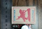
Particular attention should be paid to the manufacture of the case. Since the amplifier operates in difficult temperature conditions, the wood must first be well dried. In this case, the boards were dried naturally in room conditions for 6 months. After finishing the boards, a body was made from them (photo in Fig. 4). The blanks were cut at the ends at an angle of 45° and glued together with “Joiner-moment” glue. After this, the body was installed near the central heating radiator and covered with a blanket. In this state, it was left to dry for another two months, after which the required holes and windows were cut out and decorative elements of the front, top and rear panels were glued in. After these operations, the body for a month


I dried myself by the radiator again, covered with a blanket. Then it was sanded and painted with the Belinka-TOPLAZUR tinting composition in mahogany color (No. 28) in four layers. All this was done so that there would be no surprises in the future when operating the amplifier.

The amplifier has a fairly intense temperature regime in the upper part of the case, while the lower compartment hardly heats up. Insufficiently dried body material (in this case, pine) can burst along the grain. I had to work hard to get a good result: for three years now there have been no complaints about the case. If you don’t want to make bars, the body can be made from plywood 15...20 mm thick, covered with veneer.
The side panels of the case are cut from tinted glass "Turquoise" with a thickness of 5-6 mm. When the amplifier is operating, they can be slightly moved back, as shown in the photo in Fig. 5; while ventilation

hull will improve significantly. To make the life of the amplifier easier, a computer cooler is installed on the rear panel, operating in two modes - at 8 and 12 V. It can be turned on or off if desired
The rear and front panels are cut from 2...3 mm aluminum, sanded and coated with clear acrylic automotive varnish from aerosol packaging.
Holes with a diameter of 5...6 mm are drilled around the lamp panels to ensure natural air convection. The top panel of the case has a protective metal grille, which fits freely into the decorative frame on this panel
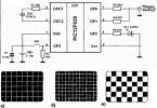
In this amplifier model, the output transformers are not quite conventional. They are made on the basis of a TS-90 network transformer with an ShL magnetic core. All windings are removed from the standard coils, and new ones are wound in bulk with a bundle of nine PELSHO wires. Of these, seven PELSHO-0.33 wires are used in the primary winding, and two PELSHO-0.8 wires - in the secondary. The connection diagram of these wires into windings is shown in Fig. 6.
A bundle of these nine wires, about 10 m long, is wound onto the frame of each coil until it is filled (about 70 turns are obtained). Next, these coils are boiled in paraffin for 15...20 minutes in a water bath C
output transformer options are also possible. 6P36S lamps have a fairly low internal resistance, and for a push-pull amplifier using such lamps, from 700 to 1000 turns of the primary winding (for the used magnetic circuit) with a tap from the middle is sufficient.
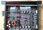
The amplifier and power supply are equipped with circuit boards made of foil-coated fiberglass. Due to the fact that they have a very simple pattern, it is cut with a cutter made from a hacksaw blade. A view of the installation of small parts and assemblies in the chassis of the blocks is shown in photo fig. 7.
On the rear panel of the case there are output terminals for both channels, input connectors, a remote control connector, a network connector, a fan switch (red key), a fan mode switch - a toggle switch (voltage 8 or 12 V), a case ground terminal and a fuse block (one in the primary network circuit and two in the anode supply circuits of each channel)
From the editor. In the case where the fan is located below powerful lamps, forced ventilation should be organized as supply ventilation.
Comments on the article:
Practical circuits of tube amplifiers using TN transformers
Scheme 1. Two-tube amplifier using 6F3P or 6F5P triode-pentodes.
The scheme is classical and does not require a detailed description of the physics of its operation.
A differential stage is used as a preliminary amplification stage and bass reflex. The anode current of each triode is 1.45 mA. In this case, the gain of the cascade from the input to each output is 25. The sensitivity of the amplifier from the input, at maximum output power, is 0.45 volts effective value.
The amplifier output stage operates with automatic bias in class AB mode. The current balance of the output lamps is established by a small (plus/minus 1.5 volts) change in their grid biases.
The power supply is made on the basis of standard TAN transformers with a bridge semiconductor rectifier and a classic U-shaped C-L-C filter. For low-voltage "current" lamps, the use of semiconductor diodes in the rectifier instead of kenotrons is preferable.
The amplifier parameters for this circuit are given in the first two lines of Table 4.
Replacing 6F3P with 6F5P will not lead to a change in the circuit, except that you will have to re-solder the wiring of the panels and turn on the windings of the output transformer. It is also possible to use “single” pentodes 6P18P, 6P43P in this circuit, and perform the differential stage of the phase inverter on a double triode 6N23P. Such a diagram is shown in the following figure. Here, a different series of supply transformers is used and the prestage is set to twice the anode supply voltage for better linearity.
Scheme 2. Three-tube amplifier for 6N23P and 6P43P or 6P18P.
The circuit is completely similar to the previous one, with the only difference that the preliminary differential stage is made on a 6N23P double triode. The anode current of each triode is 6.25 mA. The gain of such a circuit from the input to each of the paraphase outputs is 14. Accordingly, the sensitivity of the amplifier from the input, at maximum output power, is 0.8 volts effective value.
If you want to supply a paraphase input signal to the amplifiers according to Schemes 1 and 2, you need to apply an inverse signal to the grid of the second triode through the capacitor available in the circuit (0.47 μF) by disconnecting its lower terminal in the circuit from the common bus. In this case, the sensitivity of the amplifier for each input will be 2 x 0.4 volts. In Scheme 1, the sensitivity of the amplifier with a paraphase signal will be 2 x 0.225 volts.
The power supply in its constituent elements is completely similar to the previous circuit, however, the physics of its operation is different. The prestage is fed with an increased voltage of + 370 volts from the bridge rectifier to provide greater gain linearity and better circuit symmetry due to the large value of the resistor in the common cathode circuit and, accordingly, a large voltage drop across it (+ 70 volts). The output stage is powered by a full-wave rectifier formed by two bridge diodes with grounded anodes, and a potential of +200 volts is drawn from the midpoint of the anode winding. The anti-aliasing filter is similar to the previous scheme.

Frequency range at half power (0.707 voltage) from 40 Hz to 25 KHz.
The sensitivity of the amplifier at maximum output power is 0.25 ... 0.3 volts.
The variable parameters of the amplifiers according to schemes 1 and 2 are summarized in Table 4.
Table 4.
| Lamps | Output tr-r. | Power tr-r. | Pout [W] | Raa [Ohm] | Ea [V] | Iao | - Eg1 [V] | Rk [Ohm] | Rc [Ohm] |
| 6F3P | TN33, 36 | TAN2, 14, 28, 42 | 9 | 5000 | 220 | 2 x 32 | 16 | 270 | 240 |
| 6F5P | TN36, 39 | TAN2, 14, 28, 42 | 14 | 4050 | 220 | 2 x 40 | 20 | 120 | 270 |
| 6P18P | TN36, 39 | TAN4, 17, 31, 45 | 9 | 5600 | 200 | 2 x 60 | 11 | 330 | 75 |
| 6P43P | TN36, 39 | TAN4, 17, 31, 45 | 15 | 3333 | 200 | 2 x 60 | 16 | 330 | 130 |
Scheme 3. Push-pull ULF on “television” lamps.
The preamplifier in this circuit is made of two stages. The mode of the first amplification stage on the triode part of the 6F1P was chosen close to the standard one with an anode current of 10 mA and an anode voltage of 93 volts. Stage gain 7.
The phase inverter is made according to the circuit of a paraphase differential amplifier based on a 6N23P double triode with a current source in a common cathode circuit. The pentode part of the 6F1P lamp was used as a current source. The differential cascade scheme is completely similar to the previous one. The anode current of each triode is 6.25 mA. The gain is 14. Thus, the total pre-gain factor will be 98.
The sensitivity of the UMZCH according to scheme 3 at maximum output power will be 0.23 volts effective value.
Since the anode supply voltages of amplifiers with VTs are rigidly fixed and determined by the above calculations, and the parameters of the “frame” and “line” lamps are largely consistent, it seems possible to develop a single amplifier circuit for 6P36S, 6P41S, 6P42S, 6P44S, 6P45S. Only the parameters of some passive elements, the inclusion of secondary windings and the type ratings of the power and output transformers will be different. Well, of course, the currents consumed from the power source and the output powers of the amplifiers will also be significantly different.
As an anode supply rectifier for an amplifier using current tubes, it is better to use a semiconductor bridge, after which a smoothing C-L-C filter is installed. This circuit, compared to a kenotron rectifier, will provide better stability of low anode voltage at high load currents. And the anode currents in these amplifiers will be very significant. A 1 kilo-ohm resistor in the negative terminal of the anode bridge limits the charging current of the filter capacitors and must be short-circuited after turning on the amplifier, but not earlier than after 5 seconds.

The variable parameters of the amplifiers according to scheme 3 are summarized in Table 5
Table 5.
| Lamps | Output transformer | Power transformer | Pout. [W] | Raa [Ohm] | Ea [V] | Iao | - Eg1 [V] | Rg [Kohm] | Sf [µF] |
| 6P41S | TN42, 44, 46, 47 | TAN31, 45 | 28 | 1620 | 200 | 2 x 70 | 27 | 27 | 330 |
| 6P36S | TN49, 50, 52 | TAN45, 59 | 32 | 1400 | 200 | 2 x 60 | 24 | 20 | 470 |
| 6P44S | TN54, 56, 57 | TAN73 | 43 | 1040 | 200 | 2 x 100 | 33 | 43 | 470 |
| 6P42S | TN58, 59 | TAN73, 108 | 49 | 920 | 200 | 2 x 100 | 33 | 43 | 680 |
| 6P45S | TN60, 61 | TAN108 | 56 | 800 | 200 | 2 x 150 | 37 | 68 | 680 |
An amplifier version using 6P44S tubes is shown in the diagram below. The balance of the output stage circuit is adjusted within small limits using a potentiometer in the screen grids. Having previously set the same lamp currents in rest mode with this resistor, the final adjustment of the symmetry of the circuit must be carried out at a nominal signal with a minimum of nonlinear distortions.
When installing amplifiers, it is necessary to remember that armored transformers TAN31, 45, 59 and rod transformers TAN73, 108 have different pin numbers.
You can also try triode connection for current lamps by connecting the screen grid to the anode; fortunately, their typical mode provides the same supply voltages for the anode and the screen grid.
You can also switch the output stage to class A mode with auto-bias - with a common resistor in the cathodes of 140 Ohms for 6P44S (6.6 W will be dissipated by this resistor, so you need to connect four 2-watt resistors of 560 Ohms in parallel), of course, adjusting anode power supply to these 30 volts, connecting in series with the anode windings the free bias windings 11-12 and 20-21. Thus, with auto-bias, the anode supply voltage will increase to approximately 230 volts. However, you will need to check the prestage supply voltage to ensure it does not exceed the 450 volt limit for electrolytic capacitors. The excess voltage will be absorbed by a 10 kilo-ohm 1-watt resistor connected directly to the positive terminal of the anode bridge before connecting it to the filter capacitor. A similar connection of a quenching resistor is shown in Diagram 2.
The same amplifier circuit will provide the necessary gain and range of the output voltage of the phase inverter for driving “regulating” lamps of the 6S19P, 6S41S, 6S33S types. But this is the topic of one of the subsequent articles.
TN transformers open up enormous circuit design possibilities in the design of push-pull tube amplifiers, even up to high-quality sound reproduction.
Experiment!
Among the creators of tube amplifiers, tubes that were previously used in televisions are deservedly popular. 6N23P, 6F3P, 6P45S are still very popular among amplifier manufacturers and this is not a complete list of such lamps. Among these lamps there are leaders in popularity, as output lamps, for example, the most popular are 6P36S and 6P42S, and this popularity is well-deserved. When performed well, the sound of amplifiers on these tubes pleases the discerning ears of many music lovers.
Below is one of the versions of a single-ended amplifier with a 6P42S output tube.
To fully power up the 6P42S, you need a signal with an amplitude of 70-80 Volts. It is quite problematic to obtain such an amplitude using a single-stage driver from a standard signal source. Therefore, it was decided to make the driver two-stage, in the first stage the E80CC performed very well, in the second stage we settled on the EL84 in triode connection, although the 6P15P and EL803 performed very well.
The output stage uses a transformer with a cathode winding, which increases the linearity of the stage and reduces its output resistance. The amplifier circuit is shown in Fig. 1.
Fig. 1 Schematic diagram of the electrical amplifier
As can be seen from the diagram, 6P42S is used with a fixed bias. As an anode current sensor, I usually use the active resistance of the cathode winding, usually it is around 10 Ohms.
The amplifier is switched on in three stages: when the general switch 1 is turned on, all filaments are preheated, after which the contacts of relay 2 close a limiting resistor of 1 kOhm and the lamps are fully heated and in the anode supply the voltage rises to approximately half. After closing the contacts of relay 3, full anode voltage is applied and the amplifier is ready for operation.
The output transformer has a reduced resistance (for the anode and cathode windings together) of about 2.5 kOhm, the cathode winding is approximately 10% of the anode winding.
Now about the output tubes. There are at least four different designs of these tubes, with the two earliest ones being the most “sounding”, with round holes in the anode. The very best has a gray-silver anode, the second in the ranking has a mouse-gray anode. The difference in their sound is very small in favor of the silver one. The latest version is similar in design to the 6P45S and sounds accordingly.
The original amplifier used BC resistors (except for the EL84 anode, there are five-watt Matsushita ones, one to one the same as Kiwame, but blue), Tesla electrolytic capacitors, interstage capacitors - K40-U9, volume control - wire PPZ-40. But this is not dogma.
In conclusion about the measured characteristics: the maximum output power was 11 W with a frequency range of 8 Hz...50,000 Hz (with a flatness of ±3 dB) and 16...35,000 (with a flatness of ±0.5 dB), Kni = 1% (with 8 W), Rout = 1.5 Ohm.
The design of the amplifier is shown in Fig. 2. There is no protective grid in the photo, which is installed for safety reasons because life-threatening voltage is present and easily accessible on the 6P42S anode caps.
6P45S is a very consumer-grade lamp! For such a healthy bandura, it is made very poorly! Firstly, there is a wide range of parameters. Secondly, the cathode and the terminal are very poorly connected, stuck with some tiny wire that burns out at any overvoltage. I screwed up about 5 lamps. Only the cathode of two of them did not burn out right away, it burned out...in a day! And only one worked for a month. To avoid desoldering, I wanted to parallel two of them, but the filament current of 5 A seemed too high. I used them in my tube high-voltage converter:
http://stalin.flyback.org.ru/tubeflyback.htm
Then I installed a 36 instead of the 45, everything has been working for about a month, the 36 actually calmly holds 600(!) volts and 30 watts at the anode. Reliable as a rock (in a good way).
Arkady Antonov
> anode power 6p36s-20 watts
This may be so, but the lamp calmly holds 27 - 28 watts at the anode... Yes, and thirty won’t scare it
From my experience, 36 sounds more convincing (versus 45)
Pronin
The best-sounding frame tetrodes, in our opinion, are 6P42S lamps WITHOUT A CHAMBER ANODE. They are, however, extremely rare, and the meaning of their production in Svetlana in 1972-1975 is generally unclear. However, they exist, you can find them. Also very good are 6P36S and 6P42s with a white “fluffy” anode. They are also absolutely “indestructible,” apparently due to the coating of the anode.
The sound characteristics of these lamps greatly depend on the modes used.
Therefore, it is difficult to talk about sound outside of these “mode” bindings.
> And anyway, what are the cutoffs for 36 and 42?
I like the 300 V, 125 mA mode for 6P42S and 300 V, 72 mA for 6P36S.
The load is absolutely correct - 2 and 4 com, respectively.
You can wind it on 2 coms, put two sockets and listen to either one 6P42S or two 6P36S in parallel.
There is no need to set 5Ts3S, the sound will be musical, but slow. Install two 6D22S, and achieve musicality by selecting parts.
And in any case, there’s no point in loading the kenotron into space.
Shalin
Well, can anyone tell me the optimal modes for this tube in a triode and the internal resistance and Mu at the operating point... I've been searching - I've listened to the amplifier on these tubes, and they play better with the same circuit design than the EL34 and much better than the EL84. Unlike 6P45S, they stably maintain the mode without floating in thermocurrents at a fixed displacement. Well, in general, do whatever you can to help. As far as I understand, there are no anode graphs for this lamp in nature - I don’t even have “ministry” in my reference book.
Gajdar
Then it’s better to use 6P36S. She plays EVEN BETTER than 6P44S
Shalin
> Hello Alexey. Since you are on the forum, tell me the mode for SE 6P36S and
> given load or a couple of options. Thanks Eduard.
For 6P36S: 330 V, 70 mA, Ra = 5 com.
I like this mode
Shalin
> Just 6P36S is similar to 6P42S of the first releases.
> And 6P36S have less spread and are more stable.
And today I was convinced of this - I was just selecting pairs from 6p36s:
We managed to choose from 15 pieces
1 perfect pair
1 imperfect quartet
4 lamps accelerated
Well, 5 pieces are completely different.
40% yield is a good result
And this ideal couple sounds very beautiful.
Beard

There are Svetlanov and Ulyanovsk 6P36S with light gray anodes - they play better than just gray ones.
Shalin
Better with "42". The 42 anode is slightly larger than the 36th and similar to it, and the 45th is
1.5 times higher and at the ends on both sides there are three rectangular holes of approximately 6x6 mm. It seems that A. Shalin posted photos of the correct 42 somewhere. 36th so - if the anode is almost white and “fluffy” or light-light gray and again “fluffy” - then you need to save it, even a used one.
HRYUN
You need to turn it on for 2-3 minutes, just long enough for the lamp to warm up. They feel normal. This is not yet serious overheating. Forty-five is a strong lady. They only collect them poorly.
The meaning of such a check is as follows. In a beam tetrode, both grids have the same pitch, and must be installed so that the grid threads are exactly opposite each other. This is how rays are formed. 6P45S and 6P36S have almost the same cathode-grid design - 4 frames with welded wires. Two frames on one side of the cathode, two on the other. It turns out two sets of rays in different directions from the cathode, to the opposite halves of the anode. Let's assume that on one side the frames are not aligned exactly. Then the beam current on this side will be less than on the other, and the anode half on this side will heat up less than the opposite. Half the lamp is a beam tetrode, and half is a conventional one. And these two tetrodes, different in characteristics, are connected in parallel. In principle, you can use a pyrometer to measure the temperature of different parts of the anode, but in the absence of one, heat the lamp for a short time until redness appears. If it turns red more on one side, it is a clear sign of a manufacturing defect. It will work fine in horizontal scanning, but it’s better not to use it in sound. There are approximately 80-90% of such defective lamps.
Oleg
Message from KHRUN
And the truth is HORROR...! I’ll tell you my terrible secret: somehow (long ago)
my 6P36S (vintage) worked for quite a long time in 250 V mode,
160 mA (40 watts, however...) with auto-bias (more precisely, almost with auto-fix, but then no one knew that it was auto-fix). And nothing, they remained alive.... Gridlik was, it seems, 51 kOhm.
Likewise. Only my used Svetlanov 6P36S worked for several months in the 100 mA 400V mode, and with a fix.
Dalka
And this is precisely the reason for the bad sound... I came across 45s that turned red on one side at 40 watts at the anode, maybe a little more. They immediately left the trash. How much power can the selected lamp dissipate before turning red?
Sergey Z
Those selected at 60 practically do not turn red. Only in complete darkness is a slight glow noticeable. Indeed, this is a good alternative to 6S33S. It is much easier to swing and much more linear.
Oleg
I looked at the triode I-V curves of the 45th.
I found one mode:
250V, 180mA, -50V on grid.
Ri = 290 ohms, Ra = 2380 ohms, alpha = 8.2.
Uam = 181 v, Iam = 76 mA,
P~ = 6.88 W.
Linearity in this mode is very high.
In the 250 V, 240 mA mode, it will not be possible to make a load of more than 1242 ohms, since then the right half of the load line will even go beyond the power curve of 60 (!!!) watts.
In a word, whatever one may say, the use of 6P45S with an anode power of more than 45 W is doubtful for me...
Shalin
6P36S are very vibration-resistant lamps with strong frame grids, they have a small microphone.
Shalin
IMHO, in comparison with the 6P36s, the 6P44S is first captivated by the novelty of the sound, then, after listening,
you understand that the sound is “prickly and rough”, but subjectively there are more highs,
when measuring a longer tail of harmonics, comparative measurements were carried out only
one output stage on different lamps, all other things being equal.
As for the spread, Svetlanov 6P44S have closer parameters than 6P36S,
for 6P44S the average spread is up to 30-35%, 6P36S up to 50%.
Everything is learned by comparison, but previously unused, selected 6P31S, IMHO have the most
natural sound, close to the sound of 2A3 in the midrange and treble.
Manakov
Dmitry, one of my 6P36S amplifiers has been working for 8 years at 20 watts on the anodes without replacing lamps. My friend has three years at 27 volts.
Somewhere Hryun pointed out that in the forced (36 watts at the anode) mode the Ri of the 6P36S drops to 450 ohms.
I myself try not to “torment” the 6P36S with more than 28 watts.
Shalin
Dmitry, this means that the lamps were not very good
Good 6P36S behave perfectly with 33-100 ohms in the grid. But anti-excitement measures are definitely needed, that’s true.
I did not test the 6P36S with more than 32-33 watts of anode power, but my friend in the amplifier with a 6P36S (my build) tinned it at 37 watts, and lives normally with a fixative and even without an anode stub.
Shalin
Push-pull tube stereo amplifier based on 6P36S tube NEW! February 25th, 2011
Finally got around to the article. Let's begin.
Tube sound differs from semiconductor sound for the better. There are many of them, but I won’t tell you. The only negative is that making a lamp is a tedious and difficult task. But it's worth it. To avoid any questions, you should read it.
I have already assembled the acoustics, so that there are no disputes, I will say right away that it has a sensitivity of 102 dB - just right for a lamp!
http://community.livejournal.com/ru_audiomania/1540.html
Let's move on to us. It is assembled according to a push-pull (PP) circuit using 6n23p lamps in the first stage and 6p36s in the output stage.
Scheme
Scheme by Sergei Sergeev with my modifications.
The 23x filaments will be connected to ground through 150 ohm connections from each pin. Also chokes for the anode. Well, I’ll put more electrolytes.
The setting consists of setting the voltage on resistors R12 and R13 to 0.55 volts.
Transformers
The first thing I did was make them.
For the network and two outputs I used iron from TSSh-170 transceivers with a plate thickness of 0.35 mm. I rebuilt the frames, although it was not easy.
Output parameters:
We divide the frame with the middle cheek. We swing the halves in different directions.
On each half:
Primary - two sections of 560 turns (10 layers of 56 turns) of PEV-2 0.355 mm wire.
R act of the primary - 98 ohms.
The secondary - between them - 112 turns of the same wire in two layers, taps from the 56th and 79th turns for 4 and 8 ohms, respectively. 112 turns - for 16 ohms.
There are three such secondary units in parallel on each half.
R act of the secondary - 0.88 ohm. Given - 352 ohms.
We connect the primary windings crosswise in series, the secondary windings in parallel. For more details, see G. Tsykin’s monograph (it’s cunning, by the way).
In total, the frame has 2240 turns in the primary winding and 112 in the secondary.
The iron naturally fits across the roof without a gap.
Each trance lasted 12 hours. Chewy. But what is the result:
I just exhausted the network to get 280V ~.
We end up with 360V at the anode, taking into account the drawdowns.
For the 23rd we wind two separate filaments.
To heat the exhaust we need 8 amperes. A standard winding will provide them without any problems. Near trans offset:
Chassis
I thought out the location and design myself. The chassis and all the trans boxes will be stamped and welded automatically at the factory, otherwise it will simply be ug (besides, I have long wanted a normal body).
(in the photo there is a model with another trans and a couple of chokes)
For reliable ground and glow I use these beautiful tires:
Well, for fastening all kinds of dowels I bought:
A trial prototype run gave the go-ahead, I liked everything, the sound was excellent!
The video is a MUST watch!!! You can see everything there.
I specifically asked a friend for a camera!
It’s a pity YouTube has degraded the sound quality, so it’s advisable to watch at least 720p, and better yet 1080p!
While there is nothing to write about, the chassis is still being welded at the factory. When it appears, I will immediately continue the article! In the meantime, write your thoughts, impressions, opinions here. I will be happy to answer your questions.
======================================== =====
Continuation.
The chassis has arrived! Everything is as I said, 2mm steel, holes only for sockets:
Then the security officer arrived in time. From the c1-1 tube oscilloscope, which is great for my purposes:
The panels will be flush:
The main idea is without a single visible bolt.
Therefore, the method of soldering flat head bolts to the chassis was undertaken. It is necessary to clean the surface very well so that it does not fall off and holds tightly. Then solder with a 100-watt soldering iron.
As a result, all elements of the circuit are located on special panels for wall-mounted installation.
The anode electrolytes are located on special holders that are thermally insulated from the chassis.
The setup involves setting the lamp and balancing modes.
Then it was decided to add shunts to the anode power supply at KBG 500V 5uF.
Sound.
The sound is as expected at a very high level. Low THD 0.5% at 28W. This will be enough for my speaker, given its very high sensitivity.
I'm currently planning my weekend caps.