From the end:
...Or not? It might work, it might not, it depends on the power reserve. What's the key?
What should I do? Change the key to a more powerful one or sculpt a second key in parallel; if IT is a throttle one, change it to a more powerful discharge diode of the drive.
Wherein: The conversion frequency will increase, and perhaps for some nodes it will be prohibitive. Then it’s time to recalculate the storage choke (although there is a reserve of 20% of the total, since it’s not easy on the pocket), well, perhaps with thicker wiring. IMHO, a device for determining the limits of the regime, aka “finger”, is always with you...
What's the point in speculating if no one has seen the diagram yet? Perhaps it is a blocking generator, or an inverter-bridge?
(meant a diagram with a description, although it is possible without) (meant the composition of the transistors/diodes used)
Well, not out of curiosity...
ADDED 12/14/2008 5:04 PM
PS: Here is the diagram from the first link on request in Google pulse stabilizer circuit:
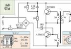
In the general case, I was talking about this kind of scheme. With options: the comparator can be integral, the switch is on a MOSFET, a choke with a gap (by the way, this ring without a gap confuses me... It can easily get enough, anyway). Here: change VD2 to a lower voltage one (3.6 V IMHO will work ), setting the exact Uout using R6... However, the output current is 1 A in no way, so: or putting 6 pieces of KD336 in parallel - it doesn’t make sense, they are ancient ones, there is no performance at all, and as the frequency increases, the voltaic speed rises. Changing the key transistor - MOSFET amperes by 5-10 amps! The conversion frequency for the used parts here is already almost limiting - this means increasing the inductance L1 (and the cross-section of the wire, which means recalculating it on a different magnetic circuit altogether). Well, accordingly, VD1 KY197 - in such modes it’s just a joke... And its performance is not so great... It’s ancient. A modern fast-diode with 10-15 amperes will whine here...
Well, that's about it. Although, this is a diagram from the FIRST link, and there are “...about 23,400 of them.” And if you also ask key stabilizer circuit, then oh-oh-oh!
How to get a non-standard voltage that does not fit into the standard range?
Standard voltage is the voltage that is very commonly used in your electronic gadgets. This voltage is 1.5 Volts, 3 Volts, 5 Volts, 9 Volts, 12 Volts, 24 Volts, etc. For example, your antediluvian MP3 player contained one 1.5 Volt battery. The TV remote control already uses two 1.5 Volt batteries connected in series, which means 3 Volts. In the USB connector, the outermost contacts have a potential of 5 Volts. Probably everyone had a Dandy in their childhood? To power Dandy, it was necessary to supply it with a voltage of 9 volts. Well, 12 Volts are used in almost all cars. 24 Volt is already used mainly in industry. Also, for this, relatively speaking, standard series, various consumers of this voltage are “sharpened”: light bulbs, record players, etc.
But, alas, our world is not ideal. Sometimes you just really need to get a voltage that is not from the standard range. For example, 9.6 Volts. Well, neither this way nor that... Yes, the power supply helps us out here. But again, if you use a ready-made power supply, then you will have to carry it along with the electronic trinket. How to solve this issue? So, I will give you three options:
Option #1
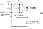
Make a voltage regulator in the electronic trinket circuit according to this scheme (in more detail):
Option No. 2
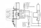
Build a stable source of non-standard voltage using three-terminal voltage stabilizers. Schemes to the studio!

What do we see as a result? We see a voltage stabilizer and a zener diode connected to the middle terminal of the stabilizer. XX are the last two digits written on the stabilizer. There may be numbers 05, 09, 12, 15, 18, 24. There may already be even more than 24. I don’t know, I won’t lie. These last two digits tell us the voltage that the stabilizer will produce according to the classic connection scheme:
Here, the 7805 stabilizer gives us 5 Volts at the output according to this scheme. 7812 will produce 12 Volts, 7815 - 15 Volts. You can read more about stabilizers.
U Zener diode – this is the stabilization voltage on the zener diode. If we take a zener diode with a stabilization voltage of 3 Volts and a voltage regulator 7805, then the output will be 8 Volts. 8 Volts is already a non-standard voltage range ;-). It turns out that by choosing the right stabilizer and the right zener diode, you can easily get a very stable voltage from a non-standard range of voltages ;-).
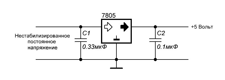
Let's look at all this with an example. Since I simply measure the voltage at the terminals of the stabilizer, I do not use capacitors. If I were powering the load, then I would also use capacitors. Our guinea pig is the 7805 stabilizer. We supply 9 Volts from the bulldozer to the input of this stabilizer:

Therefore, the output will be 5 Volts, after all, the stabilizer is 7805.

Now we take a zener diode for U stabilization = 2.4 Volts and insert it according to this circuit, it is possible without capacitors, after all, we are just measuring the voltage.

Oops, 7.3 Volts! 5+2.4 Volts. Works! Since my zener diodes are not high-precision (precision), the voltage of the zener diode may differ slightly from the nameplate (voltage declared by the manufacturer). Well, I think it's no problem. 0.1 Volt will not make a difference for us. As I already said, in this way you can select any value out of the ordinary.
Option #3
There is also another similar method, but here diodes are used. Maybe you know that the voltage drop across the forward junction of a silicon diode is 0.6-0.7 Volts, and that of a germanium diode is 0.3-0.4 Volts? It is this property of the diode that we will use ;-).
So, let's get the diagram into the studio!

We assemble this structure according to the diagram. The unstabilized input DC voltage also remained 9 Volts. Stabilizer 7805.

So what's the outcome?

Almost 5.7 Volts;-), which was what needed to be proven.
If two diodes are connected in series, then the voltage will drop across each of them, therefore, it will be summed up:

Each silicon diode drops 0.7 Volts, which means 0.7 + 0.7 = 1.4 Volts. Same with germanium. You can connect three or four diodes, then you need to sum the voltages on each. In practice, more than three diodes are not used. Diodes can be installed even at low power, since in this case the current through them will still be small.
The voltage of a vehicle battery, as well as its capacity, are the most important indicators of this automotive unit, on which its functionality and quality of work directly depend. Batteries are used to start the power unit, so every car owner should know what the normal voltage of a car battery is, constantly maintaining it in working condition. Of course, I have already touched on this topic in previous ones, but today I want to clarify this information...
To begin with, I would like to say that modern cars no longer have devices that measure “Volts,” although they used to exist. Therefore, to determine the voltage, you first need to get a multimeter. I would like to note that it is advisable to check the battery voltage at least once a month or two in order to take timely measures.
Standard for basic battery properties
What minimum value should this value be in order to start the engine? There is no exact indicator here. In the standard state, this property for a fully charged battery should average 12.6-12.7 volts.

Depending on specific conditions, this indicator may vary slightly, and there is nothing wrong with that. For example, some manufacturers assure that their products have a voltage of about 13 - 13.2 V, this is acceptable, but I want to warn you right away.

You should not measure the voltage immediately after charging the battery, as many experts write, you need to wait at least an hour, then it should drop from 13 to 12.7 Volts.
But it can go the other way when it drops below 12 volts - this indicates that the battery is 50% discharged.
In this case, the device will need urgent charging, since its operation in this state is guaranteed to lead to sulfation of the lead plates. This reduces both the performance of the battery and its service life.
But even in the case of such a low voltage, it is quite possible to start the engine of a passenger vehicle. If the battery is in working condition, it does not require repairs and the generator charges the battery while the engine is running, the device can be safely used even in this condition.
In the same case, when this electrical parameter of the battery drops below 11.6 V, the battery is almost completely discharged; its further use in this state without recharging and testing for functionality is impossible.
Thus, the normal voltage level is in the range of 12.6 - 12.7 Volts (rare, but possible up to 13.2 V maximum.)
However, in practice this is very rare. Most often for passenger cars it is 12.2-12.49 volts, which indicates an incomplete charge.

But there is nothing wrong with this: a decrease in the performance and quality of the device begins if there is a decrease to 11.9 volts or lower.
Under load
Voltage can be divided into three main indicators:
- Nominal;
- Actual;
- Under load.
If speak about rated voltage , by the way, it is customary to indicate it in literature and other materials, it is equal to 12V, but this figure is actually far from the actual parameter, I am silent about the load.
As we already said, normal battery operating voltage a passenger car is 12.6 - 12.7 volts. But in fact, the actual indicator is more reliable, which can range from 12.4 volts to approximately 12.8 V. I want to emphasize that this parameter is taken without load, which is said at rest.
But if we apply a load to our battery, the parameters will be completely different. The load is mandatory, this test shows the battery’s performance, because often all batteries can withstand normal voltage, but “dead” ones cannot withstand the load.
The essence of the test is simple - a fully functional battery is placed under a load (using a special device - a “load fork”) that is twice its capacity.

That is, if you have a battery with a capacity of 60 Am/h, then the load should be 120 Amperes. The duration of the load is approximately 3 - 5 seconds, and the voltage should not drop below 9 Volts; if the indicator is 5 - 6, then your battery is either discharged or almost dead. I would also like to note that after the load, the voltage should recover in about 5 seconds to the normal value, at least 12.4.
When there is a “sag”, the first thing you need to do is charge the battery, and then repeat the experiment with the “load fork”; if a large sag is not noticed, then the battery needs recharging. Watch a video about testing under load.
A few words about electrolyte
The main parameter that determines the voltage level in the battery is the density of the electrolyte that is inside this device.
When the battery is discharged, acid is consumed, the share of which in this composition is 35 - 36%. As a result, the density level of this liquid decreases. During the charging process, the reverse process occurs: water consumption leads to the formation of acid, which results in an increase in the density of the electrolytic composition.

In the standard state at 12.7 V, the density of this liquid in the battery is 1.27 g/cm3. If any of these parameters decreases, the other also decreases.
Reduce voltage in winter
Car owners often complain that in winter, when there is severe frost, the main parameters of the battery drop, as a result of which the car does not start. Therefore, some drivers take the battery into a warm place at night.
But in reality, things are not quite like that. At negative temperatures, the density of the electrolyte changes, which, as already noted, affects the voltage level. But if the battery is sufficiently charged, the density of the electrolyte increases in cold weather, and as a result, the second of the most important properties also increases. Therefore, a sufficiently charged battery is not in danger even in severe frost. If you leave it discharged in cold weather, the density of the electrolyte will decrease, as a result of which problems will arise with starting the car engine.

Problems with using and starting a vehicle’s power unit in winter are not associated with a decrease in the basic parameters of its battery, but with the fact that the main chemical processes inside it at negative temperatures are slower than in normal times.