Type: safety shut-off valve of low controlled pressure.
The PKN valve is a semi-automatic shut-off device designed to hermetically shut off the gas supply.
The PKN valve automatically closes when the controlled pressure goes beyond the set upper and lower limits. The valve is opened manually. Arbitrary opening of the valve is excluded.
The operating conditions of the PKN valve must correspond to the climatic version UHL category 2 GOST 15150-69 with an ambient temperature from minus 35 to plus 45 ° C.
The PKN valve is manufactured with nominal bore sizes DN 50, 100 and 200.
Examples symbol valves:
Safety shut-off valve with conditional stroke DN50 of low controlled pressure: - Valve PKN-50 TU 3710-001-1223400102013.
The manufacturer guarantees the normal operation of the PKN valve for 18 months from the date of commissioning or 24 months from the date of production, subject to compliance with the rules of storage, transportation, installation and operation.
Average service life: up to 15 years.
Basic parameters and specifications PKN valve
| Name of parameter or size | PKN-50 | PKN-100 | PKN-200 |
| Working pressure at the inlet, MAP, no more | 1,2 | ||
| Conditional bore, DN, mm | 50 | 100 | 200 |
| Controlled pressure setting limits, MPa - lower - upper |
0,0003 - 0,003 0,002-0,06 |
||
| Construction length, mm | 230 | 350 | 600 |
| Overall dimensions, mm - length - width - height |
390
310 480 |
425
320 580 |
600
390 720 |
| Weight, kg, | 33 | 73 | 140 |
Design and principle of operation of the PKN valve
Valve-type housing 1 is connected to adapter flange 2. A cover 3 is attached to the adapter flange. A membrane 4 is clamped between the cover 3 and the adapter flange, the effective area of which for a PKV-type valve is 8.5 times less than for a PKN-type valve. A large spring 5 is installed in the cover 3, the force of which is changed by means of a plug 6, and a small spring 7, the force of which is changed by means of a rod 8. Inside the body I there is a valve 9. The valve sleeve 9 moves in the direction of the post 10, screwed into the body, and the rod valve 9 into the hole in the adapter flange 2.
The valve 9 is lifted using a fork 12 mounted on a rotary shaft 13, at the end of which a lever 14 is attached.
Valve 9 has a device that acts as a bypass valve to equalize the gas pressure before and after valve 9 at the time of its opening. When the valve is opened, the lever 14 engages with the anchor lever 15 installed on the adapter flange 2. The rocker arm 16, installed in the cover 3, is connected at one end to the membrane 4, and at the other to the hammer 17.
To open the valve, it is necessary to raise the lever 14 until it engages with the anchor lever 15. In this case, the valve 9 rises and opens the passage for gas, which through the impulse tube will flow under the membrane 4. The valve is adjusted to the lower response range by rotating the rod 8, and to the upper range - by rotating plug 6.
If the controlled gas pressure is within the specified limits, the rocker arm 16, connected at one end to the membrane 34, and the other will align with the hammer stop 17, which will be locked in a vertical position, raised manually.
If the controlled gas pressure increases above the specified upper limit set by the large spring 5, the membrane 4, overcoming the force of this spring, will go up and turn the rocker arm 16, the outer end of which will disengage with the hammer stop 17. Under the action of the load, the hammer 17 will fall and hit the the free end of the anchor lever 15, which will release the lever 14 mounted on the shaft, and the valve 9, under the influence of its own weight and the weight of the lever 14, will lower down to the saddle of the housing I and block the passage of gas. If the controlled gas pressure drops below a predetermined limit set by the small spring 7, the membrane 4, under the action of this spring, will go down and lower the inner end of the rocker arm 16. In this case, the outer end will go down and lower the inner end of the rocker arm 16. In this case, the outer end of the rocker arm 16 will come out of engaging the hammer stop, which will fall and close the valve.
Installation and operation of the PKN valve
Installation and operation of the PKN valve is carried out in accordance with the Safety Rules in gas industry. The PKN valve is installed so that the direction of gas flow coincides with the direction of the arrow on the valve body.
Before installing the valve, it is necessary to re-preserve the external surfaces.
Installation of the device in places with negative temperatures is permitted provided that there is no condensation of water vapor in the passing gas at these temperatures.
The PKN valve should not be installed in environments that are destructive to aluminum, cast iron, steel, rubber and zinc coating.
The PKN valve is mounted on a horizontal section of the pipeline in front of the pressure regulator. The membrane must be in a horizontal position. The gas inlet must correspond to the arrow cast on the body.
The PKN valve with its supporting surface is installed on brackets or stands and does not require additional fastening.
The impulse tube should be connected to the nipple (welded) and, if possible, should have a downward slope from the head and should not have sections with the opposite direction of the slope in which condensate can accumulate.
Connecting the UK tube to the lower quarter of the horizontal pipeline in which the pressure is controlled is not allowed.
The impulse is taken after the pressure regulator.
In the factory version, the valve lift lever is located on the left along the gas flow. If, due to installation conditions, such an arrangement is inconvenient, then it can be reinstalled. To do this, unscrew the nuts, remove the assembled head, swap the plugs and turn the fork axle over. Place the lever on the axle so that the axis of the lever bar coincides with the direction of the fork axis in the same plane, then secure the lever with a nut.
Install the head by turning it 180° relative to its original position and tighten the nuts. After installing and reassembling the valve, you should check the reliability of knocking out the anchor with a hammer, and that all connections are sealed with air, nitrogen or working gas at a pressure of 1.2 MPa. All sealing points of the sub-membrane cavity of the adapter flange must be pressure tested for tightness for PKN-0.1 MPa valves.
For tightness of closing the valve, the pressure is 1, 2 MPa and 0.002 MPa. Air leakage at connections and seals is not allowed.
The PKN valve, after being adjusted by the consumer to the required response pressure, must be sealed.
Upon completion of installation and pressure testing of the valve, the operating parameters should be adjusted.
First set the lower limit of rotation of the rod 8. During adjustment, you should maintain the pressure in the impulse tube slightly above the set limit, and then slowly reduce the pressure and make sure that the PKN valve operates when the pressure drops about the set lower value. Then set the upper limit of rotation of the plug 6. During adjustment, the pressure should be maintained slightly higher than the set one lower limit.
After completing the adjustment, increase the pressure and make sure the valve operates when the upper limit is reached.
Transportation and storage of the PKN valve
Transportation of PKN valves in packaged form can be carried out by any type of transport, except sea, in accordance with the rules for the carriage of goods in force for this type of transport.
During long-term storage in a warehouse, valves must be re-preserved after one year of storage with preservation oil K-17 GOST 10877-76 or other lubricants for group II products according to protection option VZ-1 GOST 9.014-78.
Shelf life is no more than 6 years.
It is allowed to transport valves in universal containers without packaging with the product laid in rows, separating each row with spacers made of boards, plywood, etc.
Possible malfunctions of the PKN valve and methods for eliminating them
| Name of the malfunction, external manifestation | Probable Cause | Elimination method |
| The hammer is not installed in a vertical working position under normal controlled pressure. | 1) Impulse tube clogged.2) Membrane rupture. | 1) Clean and blow out the impulse tube.2) Change the membrane. |
| After closing the valve, gas continues to flow. | 1) The valve does not fit tightly to the seat. | 1) Check to see if anything has gotten under the valve.2) Check for scratches on the saddle.3) Check the elasticity of the valve rubber.4) Check that the lever is installed correctly relative to the valve. |
Shut-off valves PKV and PKN are semi-automatic shut-off devices. Their purpose is to hermetically shut off the supply of non-aggressive hydrocarbon gases. PKV and PKN are produced with high (PKV) and low (PKN) controlled pressure, and have a nominal bore of 200, 100 or 50 millimeters. The climatic design of the devices complies with UZ GOST 15150 (from –40 degrees Celsius to +45 degrees Celsius).
If the level of pressure to be monitored goes beyond the lower and upper setting limits, the PKV or PKN shut-off valve automatically closes. The valve can be opened manually. Arbitrary opening of the PCV or PKN valve is excluded.
Main technical characteristics of PKV and PKN valves
 Shut-off safety valves PKV (PKN) DU 200, 100, 50 are used to stop the supply natural gas to the consumer if the pressure level goes beyond the specified limits. These valves are installed in gas control units (GRU) and gas control points(hydraulic fracturing). The valves are produced in two versions - high pressure(PKV) and low pressure(PKN). The climatic design of the valves is U, category 4 according to GOST 15 150-69.

Shut-off valves PKN, PKV - controllable valve pressure setting limits
Purpose of the PKV and PKN valves
Shut-off safety valves PKV and PKN (hereinafter simply valves) in automatic mode stop the supply of natural gas to users if the pressure level increases or decreases beyond established limits. The working medium for the valves is natural gas in accordance with GOST 5542-87. Valves are used on high, medium and low pressure gas pipelines in gas consumption and gas distribution systems.
The conditions in which the valves are operated must comply with the UZ climatic design in accordance with GOST 15150-69 (limit operating air temperature values from minus 40 to +45 degrees Celsius).
In terms of pressure, two versions of the valves are produced, namely with high or low outlet pressure, with nominal bores of 200, 100 and 50 millimeters, as well as in two versions according to the location of the control levers - left or right. The right-hand version of the shut-off valve is the version in which the control levers are on the right when looking at the inlet flange of the device. If the levers are on the left, the execution is considered left-handed.
The valve seal tightness class is “A” according to GOST R 54808-2011.
Installation and operation of PKN and PKV valves
Installation and operation of PKN and PKV valves must be carried out by representatives of a construction and installation organization, or representatives of an operating organization that is accredited for commissioning, construction and installation work gas distribution networks. Installation and operation must be carried out in accordance with the requirements of GOST R 54983-2012 and SNiP 42-01-2002 (SP 62.13330.2011), “Safety Rules for Gas Distribution and Gas Consumption Networks” as well as the device operating manual.
Only persons who are familiar with the operating rules of the valves, have undergone workplace safety training, have also been trained in safe working methods and have Rostechnadzor certificates are allowed to carry out installation and maintenance of PKV and PKN valves.
Operating principle of PKV and PKN valves
The valve works like this: in the open position of the device, the anchor hook and the lever pin are interlocked. The lower end of the hammer rests on the protrusion on the anchor lever.
The hammer pin rests on the right protruding end of the rocker arm, and its left end fits into the annular groove of the rod.
When the level of controlled gas pressure is within the established limits, the lower end of the spring, through the washer, rests against the protrusions of the head cover and glass, and does not press on the membrane. Under the influence of pressure, the membrane takes a middle position. The adjusting screw nut is pressed against the spring plate.
The rocker arm is engaged with the hammer pin and is approximately in a horizontal position.
When the gas pressure under the membrane exceeds the limit set by the spring, the membrane with the rod begins to rise, thereby compressing the spring. In this case, the right end of the rocker disengages from the hammer pin, and its left end rises. Next, the hammer falls and hits the end of the anchor lever. The lever disengages from the anchor and falls, causing the valve to close.
When the pressure level under the diaphragm falls below the limit set by the spring, the rod and diaphragm begin to descend, the right end of the rocker arm disengages from the hammer pin and rises, causing the valve to close, as in the previous case.
Design of PKV and PKN valves
 Locking safety valve has a valve-type flanged housing. Inside this body there is a seat that closes the valve with a rubber seal.
The valve hangs on the stem. Top end The rod moves into the hole in the head, and its lower end moves along the guide post.
By means of a pin, the valve stem engages with a fork, which is mounted on the axle. At the end of the axle there is a fixed lever with a load. The axis coming out of the body is sealed with rubber rings.
The main valve has a built-in small bypass valve, the purpose of which is to equalize the pressure before and after the valve before. How to open it. When the valve opens, the rod will first begin to move, due to which the bypass valve will open and the pressure will equalize in the cavities of the body. This will open the main valve. When closing the valve, the main valve sits on the seat, and after that, under the influence exerted by the lever, the rod is pressed against the seal, and the bypass valve closes.
There is an attached head on the top flange of the housing. Its upper part forms a submembrane cavity to be controlled by pressure. A membrane with a rod is attached between the cover and the head.
A controlled pressure adjustment mechanism is located inside the lid.
The pin with a stop rests against the hole in the upper end of the membrane rod. A washer is placed on the stop, which rests on the protrusions on the lid glass. A small spring rests on the stop, which determines the setting of the lower limit of the pressure to be monitored. The force is determined by moving the adjusting screw.
The spring rests with its lower end on the washer. It defines the upper limit setting for the pressure to be monitored. The force is changed by moving adjusting glass. A controlled pressure pulse is supplied through the nipple under the membrane. 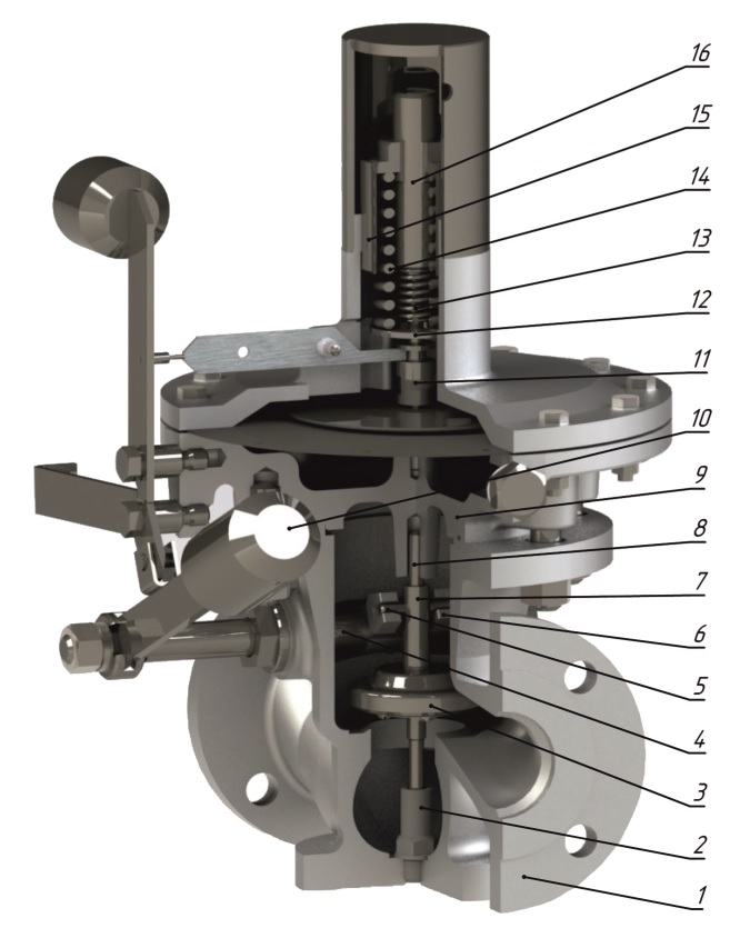
Despite the fact that almost all modern gas control points (GRP) have high performance characteristics, absolutely any hydraulic fracturing can fail completely or partially. The main task of the personnel who service the hydraulic fracturing unit is the timely detection and elimination of equipment malfunctions. What problems do inspection and repair specialists most often encounter? gas control equipment? What causes emergency situations? How to prevent equipment failures?..
Threaded and flanged connections
The most dangerous and, unfortunately, the most common accidents at hydraulic fracturing occur due to natural gas leaks. Hydraulic fracturing is not only special equipment, but also a huge number of threaded and flanged connections. For a gas leak to occur, one seemingly trivial violation of the technology for installing connecting elements is enough - it is enough to tighten one or another bolt incorrectly, use bolts of different diameters for fastening, or install gaskets made of low-quality materials. Elimination of an emergency situation of this type- the most complex procedure from the entire list of repair work gas equipment: it is necessary to eliminate a natural gas leak with the utmost care, using exclusively modern methods and materials. Thus, to replace gaskets in flange connections, it is recommended to use only klingerite and paronite gaskets thoroughly soaked in oil or gaskets made of oil- and petrol-resistant rubber. Impregnation of gaskets with oil paints or white paint, as well as the use of several “gasket” layers, is a gross violation of technology, which sooner or later will lead to new accidents at hydraulic fracturing.
The likelihood of a natural gas leak can be reduced only if, if possible, the hydraulic fracturing operation scheme is optimized and the number of connecting sections is reduced. If the gas distribution center has an auxiliary room intended to accommodate heating equipment, then in order to prevent the consequences of accidents, it is recommended to pay attention to the density of the partitions separating the rooms. In gas control points with stove heating, an important safety condition is the tightness of the metal casing on the heating equipment.
Rotary gas meters
A failure in the operation of hydraulic fracturing, leading to a leak of natural gas, can often be associated with the failure of rotary gas meters. The most common causes of leakage in in this case- loose tightening of union nuts of impulse gas pipelines, faulty gaskets, misalignment of connecting flanges, etc.
If the meter rotors themselves do not rotate or the meter operates, creating a pressure drop above the permissible parameters, then it is recommended to check the space between the walls of the chamber and the rotors - it is quite possible that it is clogged with mechanical impurities. If boxes with gears- “wet cleaning” of wheels and filling is recommended clean oil in a box. There are often situations when the rotors rotate, but the meter itself does not cope with its functional responsibilities - it does not show the consumption of natural gas or shows “wrong” data. Reasons for exit rotary counter In this case, there may be several failures - the gearbox is clogged, the gap between the walls of the chambers and the rotors has changed larger, or the counting mechanism has simply broken down.
Gas filters
Gas leaks often occur due to the fault of gas filters, which become clogged with mechanical impurities during operation. The main sign that the gas filter is clogged is a significant pressure drop due to increased resistance to the flow of natural gas. The pressure drop across the filter can cause the metal mesh of the cage to rupture. Avoid occurrence emergency situations due to a faulty gas filter, this can only be done by regularly checking the pressure level. If deviations from the norm are observed, it is recommended to clean the gas filter from mechanical impurities.
Valves
Malfunction of valves is also one of the reasons for natural gas leaks. Let's look at several options for how and why valves fail. First, gas leakage can occur due to wear of the sealing surfaces on the body and disks: physical wear of the sealing surfaces allows natural gas to “slip” even through a closed valve. Secondly, the valve itself may well be broken - the discs have come off the spindle, the spindle is bent, the valve flywheel is broken, or cracks have appeared in the oil seal box, etc.
Safety shut-off valves
Another problem that arises during the operation of hydraulic fracturing is the failure of safety shut-off valves. If the valve does not shut off the supply of natural gas, then it is quite possible that the valve is clogged or there is some defect in the seat. This type of malfunction can only be identified and eliminated after disassembling the valve. Meanwhile, the valve can remain open and allow gas to pass through even with defects such as sticking levers or sticking rod. Such a malfunction can be detected when visual inspection devices. On the contrary, if the valve, as expected, shuts off the supply, but the pressure of natural gas is not increased by the regulator, then the impulse tube may have become clogged, the head membrane has ruptured, or the “fuse” has spontaneously closed due to strong vibration hydraulic fracturing equipment or errors were made when setting up the valve. If the valve does not open during adjustment, then most likely the valve stem is stuck, the valve has become detached from the stem (this malfunction can be detected when the valve is lifted), or the bypass valve is clogged.
Pressure regulators RD
When operating gas regulators of the RD type, in some cases an increase in output pressure is observed. This happens due to a malfunction of the regulator. In particular, an increase in output pressure occurs if there is a defect in the valve seat, the integrity of the membrane is compromised, the soft seal of the valve is damaged, or the elastic force of the spring is not suitable for the pressure mode selected when setting. An equally common malfunction is the release of gas into the atmosphere through the safety device (PU) of the regulator. Most often, gas discharge occurs due to errors in setting the safety device, due to clogging of the PU valve or the appearance of defects in the PU seat. If the natural gas pressure at the outlet of the RD regulator gradually or sharply drops, a gas service technician will need to check to see if the spring is broken, the regulator valve is clogged, or the gas filter installed upstream of the regulator is clogged. If pressure pulsation is observed during operation of the regulator, then most likely there is a low flow of natural gas (compared to the throughput capacity of the regulator), the impulse tube is clogged, or an error was made when choosing the location for attaching the impulse tube to the gas pipeline.
Pressure regulators RDUK and RDSC
Sometimes it happens that RDUK or RDSC does not supply gas to consumers. Eliminate this type malfunctions can be detected by checking the integrity of the diaphragm, the functionality of the pilot regulator adjusting spring, and inspecting the discharge impulse tube for clogging. In addition, it cannot be ruled out that the pilot valve is clogged or frozen. If the diaphragm ruptures, a service technician will need to disassemble gas regulator and install a new membrane. A faulty pilot adjuster spring can be identified by visual inspection while removing the spring. If the RDSK or RDUK increases the gas pressure, then the valve may not be completely closed, the valve stem is stuck, or the impulse tube is clogged.