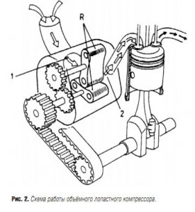
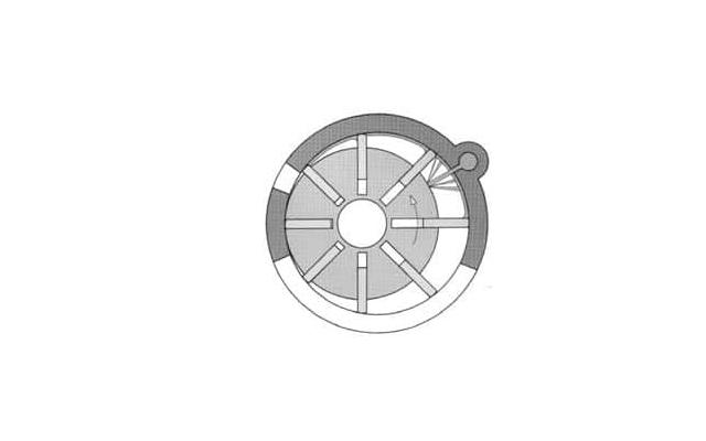
And now about compressors! The principle of operation of a vane compressor is based on the rotation of a rotor eccentrically placed in a cylindrical housing, and the movement of plates (blades) movable in this rotor. Centrifugal forces ensure that the plates are pressed against the compressor housing. Suction into the compressor occurs in the process of changing its working volume from minimum to maximum, and injection - after a given air compression and until the working volume is reduced to a minimum. On fig. 1 shows that the compressor contains a housing (1) with inlet and outlet windows, a rotor (2) and an intermediate rotary housing (3) with windows for air inlet and discharge.
The rotor is placed in a housing with eccentricity and contains plates (4) placed in the grooves (5) of the rotor.
When the rotor rotates together with the intermediate housing (3), its working cavities located between the plates, the rotor and the housing change their volumes. The figure shows that the working volume of the cavity currently located in the upper part is the largest, and the working volume of the cavity in the lower part is the smallest. On the right in the figure, the working volumes increase, and on the left, they decrease. In this case, air is sucked in, as shown in the figure, then the charge is compressed in the working cavity and forced into intake manifold engine. In the simplest version, the compressor may not have a casing (3). The plates (4) can move relative to the walls of the body (1) itself. However, in this case, problems arise with their wear, with the sealing of working cavities, especially when passing through the plates at the inlet and outlet windows.
 It is known that machines of this type are used as pumps for supplying liquids (oil, fuel pumps etc.). Some light diesel engines use fuel pumps of this type to provide sufficient high pressure fuel injection A feature of the use of such machines for supplying air lies in the complexity of organizing the lubrication of the plates (blades), since the air supplied to the diesel engine must be clean, without oil impurities, which in the cylinder can create a combustible mixture and ignite spontaneously at any time.
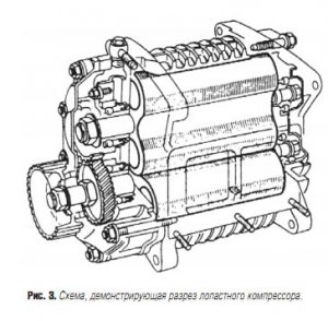
Of particular difficulty is also the problem of heating the compressor. Thanks to the intermediate housing (3), there is no friction of the plates against the housing, which alleviates the problem of overheating.
The advantage of the compressor is the ability to rotate its rotor synchronously with the engine shaft, due to their corresponding rigid connection, which provides a proportional increase in compressor performance with an increase in the demand for engine charge air.
In addition, the compressor begins to supply air instantly at the beginning of the rotation of the motor shaft and, consequently, the compressor itself. The design of the compressor is relatively simple and cheap, and its dimensions are acceptable for supercharged engines.
 Vane compressors provide an increase in boost pressure up to 0.6 - 0.7 bar above atmospheric level. IN maximum conditions it is possible to achieve a displacement ratio of 3:1 with an adiabatic efficiency level of about 0.4 - 0.5. These compressors are often used for supercharging gasoline internal combustion engines. Successes in the creation of such machines, competing with vane compressors, have been achieved by Cozette, Zoller and Powerplus. Companies "Centric" and "Bendix" have improved such compressors, significantly reducing the problems of their lubrication and cooling.
However, the problems of limiting the maximum achievable speed, lubrication and cooling problems still limit its use for supercharging diesel engines.
Rotary compressors are equipped with a rotating compression element. These include screw compressors. The market for screw compressors is diverse. However, the basic principles of the design and operation of a screw compressor are the same for almost all manufacturers. In these compressors, the pressure is reduced by the rotation of the screws.
The principle of operation of the screw compressor has been known for over 120 years, the design has been developed since the 30s of the twentieth century and was patented in 1934. The development of the screw compressor is a success story of the 20th century. Initially, they were not in such demand, as the production of rotors was expensive. But as a result of developments, this problem was solved. Screw compressors are used if it is required to provide the enterprise with a large amount of compressed air. Screw compressors are characterized by low vibration and noise levels. The advantages of screw compressors include their ease of maintenance.
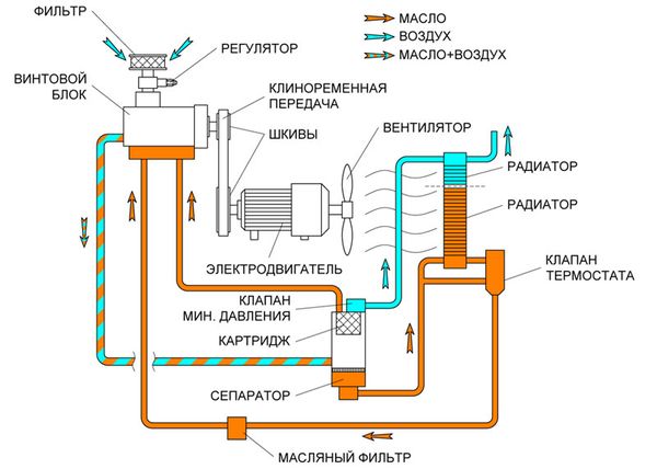
Compressor diagram
Screw block - an important component of the compressor is very reliable with a service life of 15-20 years. The screw assembly can operate at variable speed, while reducing the speed of the screws changes only the amount of compressed air.
There are no parts on the screw compressor that cause significant vibration and noise. Therefore, the screw compressor can be installed directly at the place of operation - in the production hall. Waste heat can be used for heating in winter.
General description of rotary compressors
Compressors are used to ensure that various gases (including air, refrigerants, natural gas and special gases: ammonia, oxygen, nitrogen, etc.) get a pressure higher than the normal atmospheric pressure.
Rotary compressors are positive displacement compressors. A positive displacement compressor creates a decrease in the volume of gas to increase its pressure.
Rotary compressors get their name from the rotating working element. They compress gases using cam rotors, liquids, screws or plates. In response to market demands, compact and efficient compressor machines have come into being through the efforts of many manufacturing companies.
Rotary compressors include compressors of the following types: screw, cam (Roots compressor), vane, scroll and liquid ring.
With the exception of differences in design, compressors of this type have several common features. Most important feature which distinguishes them from reciprocating compressors is the absence of a large number of valves. Rotary compressors are lighter than piston compressors, have a simple constructive solution, can be with one or more rotors. The design of the rotor distinguishes the types from each other, and also the mode of operation and size are unique to each type of compressor.
Rotary compressors are often a single driven unit. In addition, there are installations with a sequential arrangement, with or without an intermediate gearbox.
Most rotary compressors are equipped with an electric motor, however, portable compressors can also be equipped with an engine. internal combustion.
Rotary screw compressor
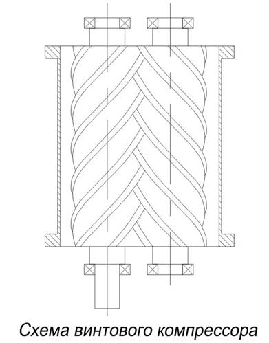
Fig 1. Screw compressor
The screw compressor is a widely used medium for compressing air, process gases and refrigerant. Effective work screw compressors depends mainly on the correct design of the rotor. This type compressors are often used in industry. In recent decades, this type of compressor has become widely popular in the gas industry for low pressure, high capacity applications. Suction pressure can be very low and discharge pressure can be as high as 400psig.
The screw compressor has performance close to reciprocating and centrifugal compressors. For example, a large 40,000 cfm screw plant is a typical application for centrifugal compressors, while small automotive air conditioning units are a typical application for reciprocating compressors.
Structural device:
The working element of the compressor is two helical rotors that rotate towards each other: when the left rotor rotates clockwise, the right rotor rotates counterclockwise. The rotors and housing are separated by a small gap. Both rotors can be attached to a drive shaft which drives the compressor into working condition. The compressor has an inlet and outlet for the working medium. Screw compressors are available in various materials. Heat treatment of rotors is usually not required.
Principle of operation
The rotary screw compressor shown in Figure 1 consists of two meshed screws or rotors that hold the gas between themselves and the compressor casing. The motor drives the male rotor, which in turn drives the driven rotor. Both rotors are located in the housing, which also has an inlet and outlet. Gas enters the compressor through the inlet and fills the voids between the rotors. When the rotors are in motion, the gas is compressed by the rotors, thereby reducing its volume. During the operation of the compressor, there is no direct contact between the rotors, which in turn means no wear on the surface of the rotors, an increase in the reliability of all equipment and a uniform gas supply.
Type description
Compressors of this type can be oil-free or oil-filled. In an oil-filled screw type compressor, lubricant is injected into the gas, which is trapped inside the housing. In this case, the lubricant is also used to cool the compressor. The gas is removed from the compressible gas-lubricating mixture in the separator. Rotary screw compressors recirculate the gas-oil mixture 1 to 8 times per minute to cool the gas and then separate them. Since screw compressors use a closed lubrication system a small amount of oil is required. The viscosity of the oil is selected depending on the specific heat of the gas.
In dry type compressors, the rotors move without lubrication (or refrigerant). Heat from compression is removed from the compressor, limiting its ability to run to one stage.
Oil-free screw compressors are usually used for special applications. Due to the lack of oil, many stages are not required as in oil-filled compressors to reach the same high pressure. Some oil-free compressors use water as the coolant. Separate ports are used for oil and air.
Most industrial screw type air compressors have motors ranging from 30 to 200 hp. These compressors use one to three helical rotors that keep the medium inside a chamber that is reduced in size to increase the pressure. Valves open when stopped to relieve internal pressure and make starting smoother.
An industrial rotary screw compressor can operate 24 hours a day, 7 days a week and will typically run longer and more efficiently when used in this manner. If the screw compressor is chosen correctly, it can be one of the energy efficient types of compressors.
Typically, an oil-filled compressor is equipped with a minimum pressure valve that prevents air from entering the pneumatic system until the minimum pressure for lubricating the compressor is reached. The oil filter removes contaminants in the oil and there is also a second oil filter, which removes large contaminants. Mounted on the compressor bypass valve to maintain pressure when the compressor is idling.
At oil-free compressor several other components. Usually these are two screw pairs, the air is cooled in an intermediate radiator between them and the gears for both screw pairs are located in the gearbox housing and the gearbox is lubricated. Oil seal and high blood pressure keep oil from getting from the gearbox to the screws.
In a rotary screw compressor, a lubricant is injected into the compressor housing. The rotating rotors come into contact with a mixture of gases and lubricant. In addition to the fact that the thin film of lubricant prevents metal-to-metal contact, the lubricant also acts as a sealant, preventing gas recompression that occurs when high-pressure hot gas enters the seal between the rotors and is compressed again. Recompression can cause the gas discharge temperature to exceed the design temperature, which will ultimately lead to a loss of plant reliability. The lubricant also acts as a coolant, removing heat during the gas compression process.
Key Benefits of Rotary Compressors
- all working parts move and can work with high speeds;
- there is practically no contact between the rotating parts, which makes them very reliable;
- uncomplicated Maintenance;
- low maintenance and operation costs;
- operation at low suction pressure;
- compactness and light weight;
- long service life.
Areas of use:
Screw compressors are commonly used for continuous operation in various industries and can be both stationary and mobile. Their power can be from 3 hp (2.2kW) to over 1200 hp (890kW) and pressure from low to over 1,200 psi (8.3 MPa).
Screw compressors work with a large number of media, among which gases, vapors or multi-phase mixtures, taking into account that the phases inside the machine can change. Typically, refrigerant and process gas compressors that run for long periods of time are highly efficient, while for air compressors, especially for mobile applications, efficiency may be less important than size and cost.
Screw compressors are ideal for most applications where compression is required:
- compression fuel gas;
- compression of gas from a borehole;
- vapor recovery;
- compression of landfill gas and recycled gas;
- compression of corrosive and or dirty process gases;
- air
- refrigeration equipment
- and etc.
Rotary compressor with lobe rotors
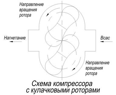
Fig 2. Compressor with cam rotors
schematic diagram rotary compressor with lobe rotors, shown in Fig. 2. Usually this type of compressor is used where a large volume is required. These machines are very reliable because the rotating parts do not touch each other, the need for oil to lubricate them is eliminated and the need for maintenance is low. The air supplied is 100% oil-free. The flow rate of the compressor is largely dependent on the operating speed.
Settings big size(over 5000cfm) are directly connected to their engines, smaller units have V-belt drive. Electric motors are usually used as drives. The compressors can also be supplied with a bare shaft for connection to the customer's drive. The scope of delivery may include a sound absorber, valves, filters, a bypass valve and compensators.
The main parts of the compressor: rotors, housing, timing gears, bearings, seals. The cam profile of the rotors is usually involute, although it can also be cycloidal. The gap between the rotors and the body is usually kept to a minimum to prevent leakage. The rotor may have two or three lobes. The body is usually made of cast iron, aluminum construction is supplied for special conditions. Splash lubrication is commonly used, but some installations do external system lubricants.
Principle of operation
The principle of operation of the compressor is similar to that of a rotary screw compressor, except that the mating lobe rotors are usually not lubricated. The peculiarity of this type of compressor is that the gas inside is not compressed. The rotors can be mounted on parallel shafts inside the cylinder. A set of gears synchronizes the rotation of the rotors. The cams do not touch each other. As the cam impellers rotate, the gas enters between them and the compressor casing, where it is compressed due to their rotation, and then enters the discharge line. In this case, the bearings and timing gears are lubricated.
Areas of use:
This type of compressors are designed to compress air and neutral gas mixtures.
Scope of application:
- Agriculture;
- construction;
- chemical production;
- electronics;
- metallurgy;
- water supply systems
- food industry.
- industrial furnaces
- pharmaceutical industry
- central vacuum supply
- degassing
- pneumatic transport
- filtration
- storage sites for organic waste
Rotary lobe rotor compressors are used where relatively constant flow is required at varying discharge pressures in material handling, liquid airing, gas production and vapor recovery, gas and air supply low pressure, waste water treatment, soil reclamation, cement plants, etc.
Rotary vane compressor
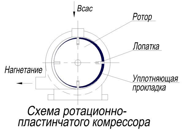
pic 3. Vane compressor
Description of type and constructive device:
A rotary vane compressor is shown schematically in Figure 3. Rotary vane compressors have a rotor with several sliding plates that are eccentrically mounted in a casing.
Compressors of this type are dry type and oil-filled. Oil compressors are the most efficient and can reach 90% efficiency. They also create more pressure than a dry type compressor.
Compressors of this type can be stationary or portable, have one or more stages, can be driven by an electric motor or an internal combustion engine. The dry type rotary vane compressor is used at relatively low pressure (2 bar), while oil-filled compressors have a sufficient coefficient useful action to achieve a pressure of 13 bar in one stage.
The most commonly used drive type is Electrical engine. On small installations (less than 100 hp), a V-belt drive is used.
The cylinder is usually made of cast iron. The inlets and outlets are flanged. For lubricated installations, the plates are made of laminated asbestos interspersed with phenolic polymers. Graphite is used in non-lubricated installations. The rotor is made of carbon steel. On larger installations, the rotor can be made from cast iron and the shaft from carbon steel.
Principle of operation
The rotor blades extend and slide along the inner surface of the cylinder under the action of centrifugal force. As a result, due to rotation, the volume of the chamber between the two blades is constantly changing. As the rotor rotates, the working medium enters the region of a larger volume, and then is supplied to the injection already as a compressed gas from the region of a smaller volume.
The lubrication process of a rotary vane compressor occurs once per operating mode. The lubricant is injected into the compressor and exits with the compressed gas and is not normally recycled. The lubricant creates a thin film between the compressor casing and the sliding plates. The sliding of the plates on the surface of the housing requires the lubricant to withstand the high pressure in the compressor system.
Areas of use:
Rotary vane compressors are used in gas recovery and gas boosting, competing with reciprocating compressors. They are inferior in efficiency, but they are quite compact, have less weight and do not require special foundation preparation for them. This type of compressor is also used to remove vapors. Rotary vane compressors have proven their reliability as compressing equipment for natural gas and methane.
Rotary vane compressors are used for:
- central vacuum supply
- cooling
- solvent extraction
- impregnation (surfaces of the material under the influence of vacuum impregnating agent)
- drying (e.g. medical products)
- degassing
- sealing solar modules
- food packaging
- vacuum forming
- tray sealing in the food industry
- packaging of non-food products
- workpiece processing
- pneumatic transport
- printing and pulp and paper industry
Special attention care must be taken to control the wear of the plates, as their wear can cause damage to the cylinder.
Liquid ring compressors
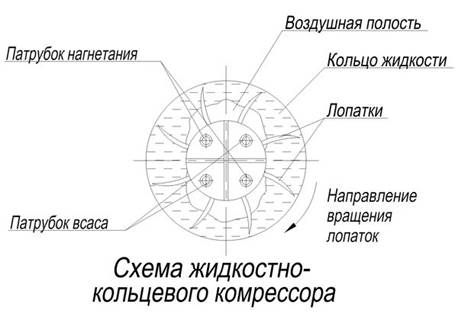
The liquid ring compressor is unique in that it uses compression by a liquid ring that acts like a piston. The single rotor is located eccentrically inside the housing. The inlet and outlet for gas is located on the rotor. Standard material is cast iron for cylinder and carbon steel for shaft, steel for rotor parts. Structurally, liquid ring compressors can be either single-stage or multi-stage.
Principle of operation
The compressive fluid partially fills the rotor and cylinder and forms a ring as the piston moves. As the piston moves, a gas pocket forms in the housing. The gas is compressed in cavities that form the surfaces of the liquid ring and the rotor. On the suction side, the volume of the cavities increases and it is filled with gas; on the discharge side, the volume decreases, the gas is compressed and supplied to the discharge line. As service fluid usually use water.
Main advantages
Areas of use:
This type of compressor is used to compress vapors, dangerous and toxic gases, as well as hot gases, including those containing dust or liquid. After the interaction of gas and working fluid, the temperature of the gas rises slightly, giving an almost isometric seal. Liquid ring compressors are used where reliable, safe work and special technological conditions are required.
Applications
- production of plastics - regeneration of process gases,
- petrochemical industry - compaction of combustible gases (fumes of gasoline, hydrogen)
- total gas transport
- removal of air from clay
- removal of oil residues
- corrosion protection for water pipes
- dust removal in the mining industry
- biogas production
- compression of anaerobic gases
- wastewater treatment and disposal
- product spillage in breweries
- loading and unloading operations
- cleaning and degreasing systems for hydrocarbon particles
- other
Scroll compressors
Structural device and type description
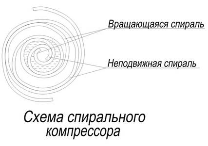
The scroll compressor is a positive displacement machine with orbital movement, in which compression occurs with the help of two scroll elements nested in each other.
Although the idea of a scroll compressor has been known for a long time, scroll compressors are enough new technology. The first patent for a scroll compressor was issued in 1905 to the French engineer Léon Croix, but it was not until 1970, with the development of high-precision machining, that a working prototype was made. Today, scroll compressors find their application in both commercial and domestic applications.
Scroll compressors are completely hermetic. The spiral block, clutch, counterweights, motor and bearings are mounted in a welded steel housing. Most air conditioning scroll compressors are vertical in design. The casing is a cylindrical vessel located vertically and divided into a low pressure part and a high pressure part. The lower part of the casing serves as a reservoir for oil and fluid. Spirals are usually made from carbon steel blanks. Particular attention is paid to the manufacture of spirals, as their precise fit is required.
Principle of operation
The scroll compressor uses two scrolls, one fixed and the other moving, connected to the motor. The spirals are nested one into the other, so that during movement, their interaction creates cavities for the working medium. The medium is subjected to compression when moving along the orbit of the movable spiral around the fixed spiral and is gradually pumped towards the center. As the cavities move, they decrease in volume and compress the gas.
Main advantages
Spiral technology offers advantages for a number of reasons. Large intake and discharge openings reduce pressure losses during suction and discharge. Also, the physical separation of these processes reduces the transfer of heat to the suction gas. Scroll compressors have the advantage of being smaller and lighter than mid-range reciprocating compressors. This effective devices operating at different compression ratios. Also, the advantages include a relatively low level of noise and vibration, high level reliability and long service life, due to the fact that a small number of parts are involved in compression and there are no valves.
Areas of use
Scroll compressors are manufactured in different sizes up to 25t. They have found wide application in domestic and commercial heating, ventilation and air conditioning systems. They are successfully used for cooling milk in bulk containers, in container transportation, in sea containers and food display cases, in water coolers. Scroll compressors are used to produce compressed air and oil-free compressed air.
Horizontal hermetic scroll compressors can be operated with natural gas, air and helium and have oil cooling. Another area of application for such a compressor is the capture of gas vapors in oil fields.
Fundamentals of the device and the principle of operation of a rotary compressor (on the example of a screw compressor)
The principle of operation of most screw compressors is as follows
Main parts of screw compressor
screw block is a pair of worm geared rotors, driving and driven in a housing that fits snugly against them. The body and rotors are delimited by a very small space between them. The rotors mesh like gears in such a way that as they rotate, the space that is created between them and the housing is progressively reduced. Any gas that enters this space is compressed.
TO category:
The device of autocompressors
Rotary vane compressors
In a rotary vane compressor, grooves are cut on the rotor in which the plates are installed. Air enters the cells between the working plates and is compressed when the rotor rotates. Rotary vane compressors compress air by reducing the volume of the working cavities enclosed between the plates of the rotating rotor and the stator cylinder of the compressor. These compressors are available in single and double stage.
The advantage of rotary compressors is the uniformity of gas supply, compactness and simplicity of design, the absence of self-acting valves and dynamic balance, which allows the use of a high-speed drive with direct connection to the compressor through a flexible coupling. These compressors with a capacity of 6-10 m3/min and a discharge pressure of 8 kgf/cm2 are used in autocompressors both with their own drive and with a drive from the engine of the base vehicle.
The efficiency of air rotary vane compressors largely depends on air leakage through the gaps between the rotor and cylinder heads.
Rice. 180. Scheme of a rotary vane compressor:
1 - suction pipe; 2 - rotor; 3 - body; 4 - working plates; 5 - cylinder; 6 - discharge pipe; O, and 02 are the axes of the stator and rotor.
Therefore, the ratio of the length of the cylinder to its diameter d for a single-stage compressor and for the first stage of a two-stage compressor should be 1.5-2.5, and the size of the end gaps is set such that, with thermal expansion of the rotor and plates in the cylinder, scoring or jamming is avoided.
The most loaded parts of the compressor are the plates. Taking into account the stresses and deformations of the plates for compressors with a discharge pressure of up to 8 kgf/cm2, the eccentricity (displacement of the rotor axis to the cylinder axis) e=0.28. The height of the installed plate is h=3.8 e. Depending on the dimensions of the machine, the pressure drop in the compressor, the material of the plates, the method of lubrication and cooling, the number of plates varies from 4 to 30. It should be borne in mind that a larger number of plates corresponds to a smaller difference pressure between neighboring cells. This reduces leakage losses and reduces bending stresses in the plates, but at the same time increases the wear of the mirror in the cylinder.
To reduce cylinder wear, plastic plates are used that are thicker than the rest. To prevent the volume of the useful area of the cylinder from decreasing due to the volume of the plates, a smaller number of plates is installed, which leads to a greater pressure drop between cells A, B, C, D (Fig. 180). A smaller number of plates is possible with abundant lubrication of the cylinder, which helps to reduce losses from leaks. At internal cooling oil injection compressor, it is necessary to have a small number of plates, otherwise gas-dynamic losses increase. Peripheral speed for steel plates is allowed up to 13, and for plastic plates - up to 10 m/s1.
The grooves for the plates in the rotors, depending on its rotational speed, are made radial (below 24 m/s1) or inclined (above 24 m/s-1) at an angle to the plane passing through the rotor axis. The rotor rotates in one direction only.
The rotary vane compressor (Fig. 180) is a compact, balanced machine. A rotor is placed in a horizontally located cylinder body. The axis of the rotor 02 is displaced (has an eccentricity) relative to the longitudinal axis of the cylinder 01 by the value e. In the grooves of the rotors there are plates that, when rotated under the action of centrifugal forces, are pressed against the surface of the cylinder.
Between two adjacent rotary plates, inner surface closed cells A, B, C and D are formed by the cylinder and the rotor. When the rotor rotates, air from the atmosphere is sucked into cell A through the nozzle; in cells B and C, a compression process occurs, the volumes of these cells gradually decrease; in cell D - the process of forcing compressed air, which is pushed out through the nozzle. Radial gaps between the cylinder and the rotor in the compressed air cut-off zone should be within 0.15-0.2 mm.
TO category: - Device of autocompressors
Rice. 01
Rice. 2
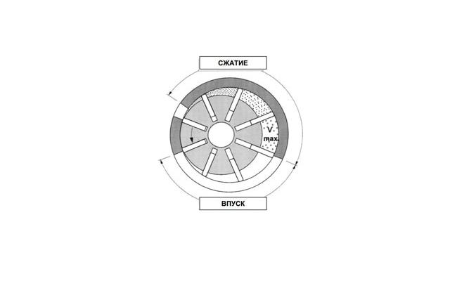
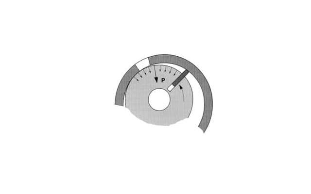
The air is compressed in several cavities that form the stator, rotor and each pair of adjacent plates and which decrease in volume in the direction of rotation of the rotor. Air intake occurs at maximum output plates from the grooves and the formation of vacuum in the cavity of maximum volume. Further, at the stage of compression, the volume of the cavity is constantly decreasing until reaching maximum compression, When plates pass by the outlet channel and compressed air is released (Fig. 2).
Plates in a rotary vane compressor are always pressed against the inner surface of the stator (Fig. 1), which creates an almost perfect seal. In the place where the rotor and the stator approach, due to the accurate machining of the surfaces and setting their relative position, touching the generatrix of the two cylinders practically eliminates leakage. Only one plate with a tight clamp to the stator surface in the sector between the inlet and outlet channels is enough to prevent air leakage from the injection zone to the low pressure zone.
Rice. 3
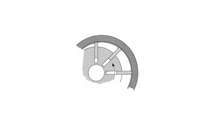
In addition, the large amount of oil that is injected into the stator to lubricate the moving parts and cool the compressed air also seals the gaps between the rotor, stator and stator end caps. The oil, which is supplied under pressure, penetrates into the gaps over the entire surface of the maximum convergence of the rotor and stator in the sector between exhaust channel and the nearest plate and reliably seals them (Fig. 3).The reliability of a rotary vane compressor is based primarily on its design features, including simplicity of design, the absence of a large number of moving parts subject to wear and failure, the absence of axial loads, and reliable lubrication by injection of abundant oil.Reliable operation and reproducibility of performance characteristics throughout the entire life of the rotary vane compressor is also ensured by the above design features, which, in particular, make it possible not to impose particularly stringent requirements on the dimensional accuracy of the main parts of the compressor.This means that the performance of the compressor is not affected initially and during its long-term operation by slight dimensional fluctuations. The plates always slide freely inside the grooves of the rotor and, tightly pressed against the walls of the stator under the action of centrifugal force, provide excellent sealing. Even a slight wear of the plates does not change this picture over time. The same applies to the end gaps between the rotor and the stator end caps, which are always reliably sealed with pressurized oil. The same is true for babbitt plain bearings, on which the rotor shaft rotates and which provide low noise and reliable performance throughout the life cycle of the compressor, almost never requiring replacement. Since the rotor is significantly smaller in diameter than the stator, the increase in the clearance between the shaft and the bearings is not a significant factor. The bearings are lubricated by pressurized oil supply without the use of a special circulation pump, which eliminates the additional risk associated with possible pump failure.
Rice. 4
No vane compressor axial load, so there is no wear on the end surface of the rotor, which never comes into contact with the end caps of the stator.
The rotor and stator are also never in direct contact. This is prevented by internal oil pressure (Fig. 4). The supply of oil for lubrication and sealing film formation is proportional to the air pressure and therefore to the radial loads generated by this pressure: the higher the air pressure, the greater the oil injection and the higher the oil pressure.
Rice. 5
The plates, when the rotor rotates, also never come into direct contact with the inner surface of the stator. Due to the abundant oil supply and the rounded edges of the ends of the plates, the plates slide freely over the oil film along the inner surface of the stator (Fig. 5). Jamming of the plates is excluded, wear of the plates is negligible. In fact, the vanes are the only part of the compressor block that is subject to any wear. At the same time, their working life is at least 50,000 hours on one working side. After installing the same plates with the second working side out, they can work for the same amount, providing a total service life of the rotary vane compressor up to 100 thousand hours.
cylinders
valves
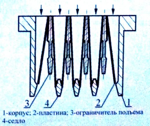
Poppet (Fig. 9)
Rice. 9. Poppet valve
lamellar
Ring (Fig. 10)
Rice. 10. Ring valve
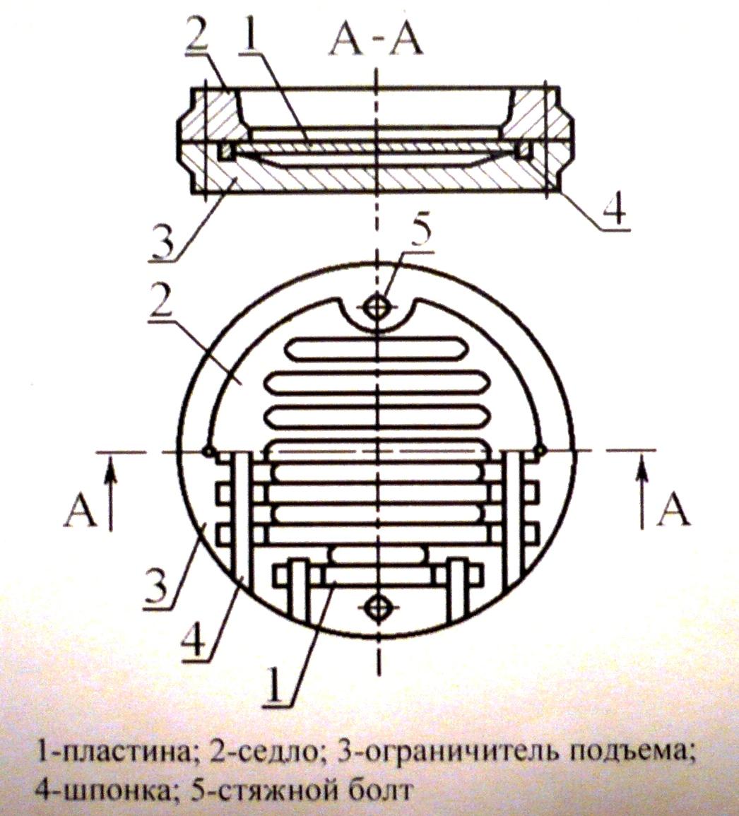
Rice. 11. Strip valve
Strip (Fig. 11)
Multi-tiered
Direct-flow (Fig. 12)
Rice. 12. Straight valve
materials
Valve arrangement
5.2. Rotary compressors.
Rotary compressors work on the same principle as reciprocating machines, that is, on the principle of displacement. The bulk of the energy transferred to the gas is imparted during direct compression.
Rotary blowers that develop overpressure up to 0.3 MPa (at atmospheric pressure at the inlet), as we said earlier, are called blowers, and those that create higher pressure are called compressors.
Rotary machines have a number of advantages over piston ones: balanced stroke due to the absence of reciprocating motion; possibility of direct connection with the electric motor; uniform gas supply; lack of valves, etc. However, they have a lower efficiency, develop a lower pressure.
The most widespread are two types of rotary machines: lamellar and with two rotating pistons.
Rotary Vane Compressor
To create pressure from 0.3 to 0.4 MPa, single-cylinder vane compressors are used. Two intercooled vane compressors installed in series can generate pressures up to 0.7 MPa.
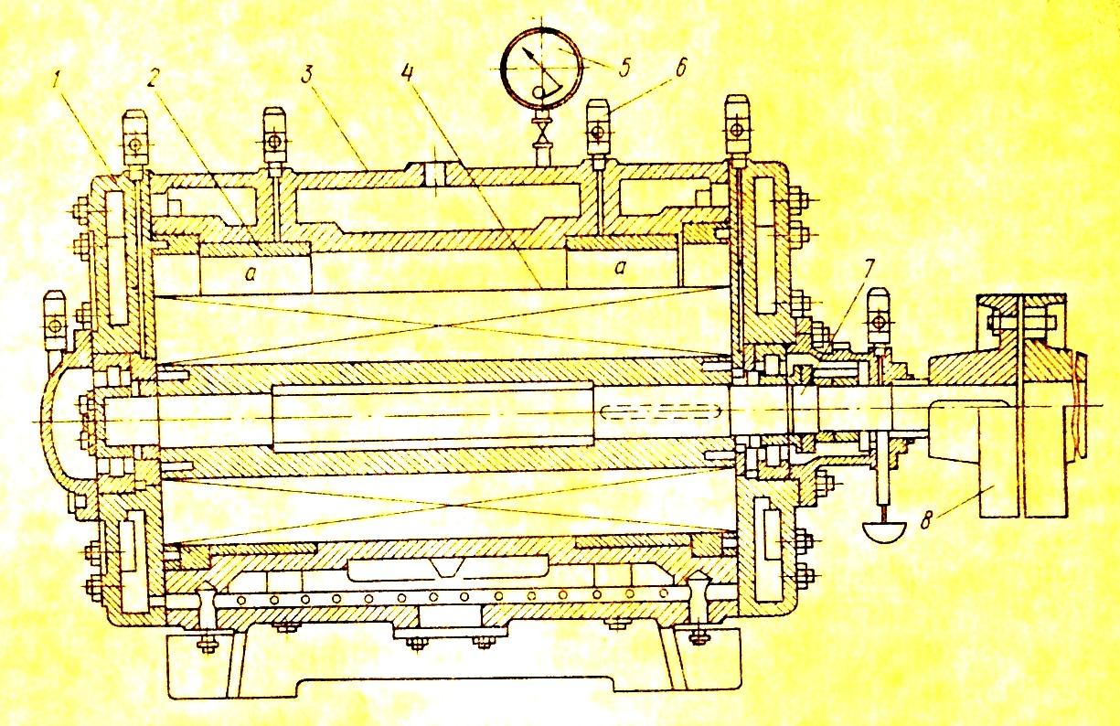
Rice. 8. Rotary vane compressor
R
Rice. 8. Rotary vane compressor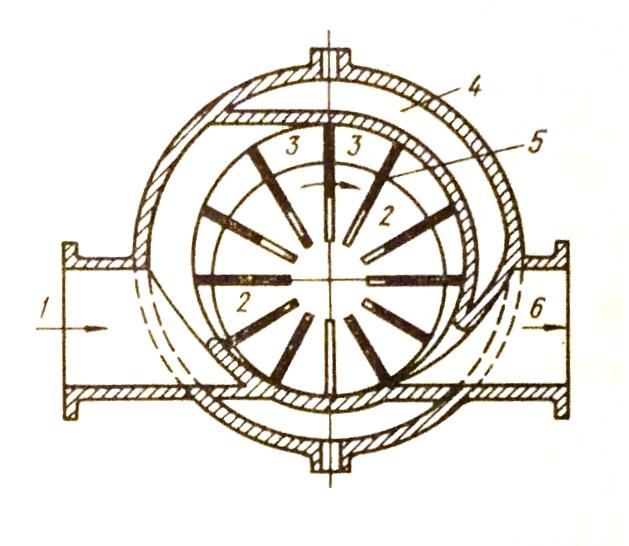
The compressor works as follows: due to the eccentric arrangement of the rotor, during its rotation, a crescent-shaped space is formed, divided by plates into separate chambers. The plates come out of the grooves of the rotor due to the action of centrifugal forces. Due to the fact that when the rotor rotates, the volume of the chamber increases, gas or air is sucked in through pipe 1. The sucked gas enters a closed chamber, the volume of which, moving with the rotation of the rotor, decreases. Compression due to a decrease in the volume of the chamber leads to an increase in pressure and expulsion of gas into the discharge pipe 6.
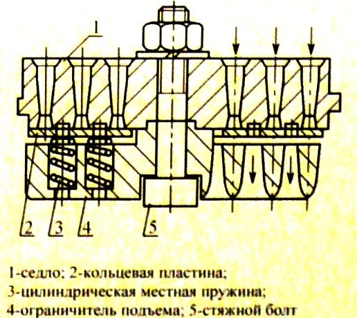
Rice. 9. Rotary vane compressor with relief rings
To reduce the friction of the plates against the cylinder, relief rings 1 are installed (Fig. 9), which cover the plates and freely rotate in the cylinder 2. Oil enters the gap between the outer surface of the relief rings and the inner surface of the recesses in the cylinder through holes 3. The number of plates in such compressors is at least twenty in order to reduce the pressure drop between the chambers and thereby weaken the flow of gas and increase the volumetric efficiency.
Rice. 9. Rotary vane compressor with relief rings
To reduce the wear of the cylinder and plates, the peripheral speed on the outer edge of the plates should be no more than 10 - 12 m/s. For a snug fit of the plates to the cylinder, it is necessary that the minimum speed be in the range of 7 - 7.5 m / s.