To ensure the operation of the battery, the car battery must be periodically charged. For charging, a home-made or branded charger can be used. It is quite possible to make a charger with your own hands from a rectifier or a computer power supply.
[ Hide ]
The design and principle of operation of the charger
A home-made device for a car battery must charge the battery from a 220-volt household network. In fact, a charger for a car battery can be called an electricity converter. The device consumes alternating current from the mains and reduces it to a parameter of 14 volts. This is the voltage level that a car battery puts out. On sale today you can find many varieties of memory, ranging from simple to multifunctional devices with many features. You can find devices that allow not only, but also to start a machine engine. This type of device is considered charging and starting.
There are also starting devices that will provide battery recharging or starting the power unit without connecting to a household network. In the device itself, in addition to the equipment that converts electricity, a conventional battery is installed. Due to its presence, the device can be called autonomous. But after each battery charge procedure, the device needs to be recharged so that it can perform this function next time.
charger device
If we talk about simple memory, then structurally they include several components. The main part of such a device is a step-down transformer device, which is designed to reduce the voltage from 220 to 13.8 volts. But the transformer node only reduces the voltage parameter. Directly the procedure for converting AC to DC produces a diode bridge. It is used to rectify the current and divide it into two poles - plus and minus. An ammeter is installed immediately after the diode component, it is designed to demonstrate the current strength. In simple design devices, pointer ammeters are used.
In the upgraded memory, digital devices are installed, and in addition to the ammeter, a voltmeter can be added to the circuit. Depending on the type of charger, the device may have a voltage selection function. Such devices can be used to recharge batteries at 12, 24 or 6 volts. Electrical circuits with positive and negative contacts come out of the diode component, they are connected directly to the battery. The whole structure is installed in the housing, a power line with a plug comes out of it, which is connected to the household network, as well as conductors with clamps. To ensure the safe operation of the circuit from power surges and damage, the device is equipped with a fusible safety element. These are the main nuances of the design of the electrical circuit.
AKA KASYAN spoke in detail about the design features, the principle of operation and the nuances of assembling a home-made memory.
Operating principle
As for the charging procedure, everything is simple here:
- The terminals of the device are connected to the dead battery, while the consumer must be careful not to confuse the poles.
- After connecting, the device connects to the network.
- When charging starts, the device produces a voltage, the current strength of which is 6-8 amperes. However, after some time, the current strength parameter decreases, which makes it possible to prevent the destruction of the plates installed inside the structure.
- When the battery is fully charged, the instrument needle will drop to zero.
General charger requirements
It is important to determine the necessary parameters for the degree of charge and density of the working solution in the battery. Otherwise, the efficiency of the memory may be reduced to a minimum.
We determine the necessary parameters when charging with direct current
Correspondence table for the degree of charge, electrolyte density and voltage
Most modern cars are equipped with lead-acid batteries. To recharge such devices, no more than 10% of the current of the total battery capacity is required. If the battery capacity is 55 Ah, then no more than 5.5 amperes of current will be required to replenish the charge. If 65 Ah - then 6.5 amperes, etc. It is allowed to use a smaller amount of current, then the charging procedure will be slower. The charge itself will be collected in the battery even at the minimum current value, but it will take more time to replenish it in the battery.
When performing calculations, it is taken into account that the current value should be no more than 10%. Therefore, the procedure will take about ten hours to complete. But it will take so much time at full discharge, and this cannot be allowed. Therefore, the recharging time in fact directly depends on the magnitude of the discharge.
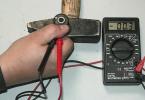
To determine the degree of discharge, it is necessary to measure the voltage:
- if the battery is fully charged, then the voltage will be about 12.7 volts;
- if the voltage is 12 volts, this indicates that the device is half discharged;
- at a voltage of about 11.7 volts, the battery needs to be charged urgently, since it is almost empty.
If the battery is discharged to the end, this will lead to rapid wear of the device. For an approximate calculation of the recharge time, the consumer must know the difference between the actual voltage, as well as the maximum battery charge. The resulting parameter is multiplied by ten, so the consumer can find out the charge replenishment time. For example, if the voltage parameter on a discharged battery is 12.1 volts, then the difference with the ideal charge value will be 0.7 V. Multiplying this number by 10, you can determine that the actual time to replenish the volume of the device will be about seven hours.
Self-made car charger: the most popular schemes
In order to make a powerful charger for a car battery with your own hands, we recommend that you familiarize yourself with the following scheme options:
- semiconductor diode + light bulb;
- rectifier;
- memory from the computer power supply;
- memory from the power adapter.
Semiconductor diode + light bulb
The household network is used as a power source. The diode component will be required to convert the magnitude of the alternating current to direct current. The light source is used as a current-limiting resistor element.
The following data are used to calculate the memory:
- The parameter of the current that passes through the light source must be calculated in accordance with the power of the light bulb. The power parameter of the device is divided by the voltage in the household network. For a 60 W light source, the current in the circuit will be 0.27 amperes.
- The actual average current is calculated. Since the diode element cancels every 50% of the sine wave, the average current will be about 0.32.
If the light source is powerful, the load current will eventually turn out to be low. This allows you to add a common diode component to the circuit, for example, 1N4004. You can find it at an electronics store. Such diodes are installed in low-power power supplies, supplied complete with anti-theft systems, etc. When assembling, one nuance must be taken into account - the strip on the body of the diode element means the cathode. This contact must be connected to the positive contact of the battery.
 A simple circuit of a semiconductor diode element with a light source
 Rectifier
A circuit with a rectifier device is used in branded memory devices that are simple in design. To assemble the device, you will need a transformer assembly with at least 12.5 volts of output voltage. The voltage parameter should be no more than 14 volts. It is allowed to use transformer devices from Soviet TVs, such devices are equipped with two windings of 6.3 volts each. If the devices are connected in series, the result will be 12.6 volts. To ensure the rectification of the current value, a diode bridge is added to the circuit, it is used as a rectifier device. It is allowed to assemble a node from individual diode elements, you can purchase a ready-made device.
During operation, the diode component will get very hot. Therefore, a radiator device must be added to the circuit from a plate of the appropriate size, it must be aluminum. Therefore, the use of a diode assembly will be more convenient. The plate is mounted by fixing it with a bolt to the central hole. When installing the plate on the work surface, it must be treated with thermal paste.
 Scheme of a rectifier for a homemade charger
 Charger from computer power supply
If you have an old PC power supply, you can disassemble it and remove all electrical circuits, leaving only:
- black conductor, this is the ground contact, connects to the negative output of the battery;
- the electrical circuit is red, this is a voltage of 5 volts, a load is connected to it for the correct operation of the device;
- yellow contact is a 12-volt voltage, connected to the positive output of the battery;
- the green contact is designed to activate the converter device, it must be fixed to the case inside the device.
To provide an imaginary load, a ceramic resistor device is used. The value of its resistance will be approximately 1.2 ohms, and the power parameter must be at least 20 watts. It is allowed to use a piece of a nichrome spiral from a heating device, a piece is cut off in accordance with the readings of an ohmmeter. Since the load will be heated, it must be installed in the power supply housing next to the fan. After that, the memory case is assembled, and the clamps are soldered to the remaining contacts, which will be used to connect to the battery.
The main disadvantage of the charger from the power supply is that it cannot fully charge the battery, since 12 volts is not enough for this.
If the device will be used for emergency charging, it needs to be finalized. The PWM controller board will be used as the main component. It is used to convert DC to serial current. The procedure for adjusting the output voltage is performed by changing the duration of the signals when operating at a constant frequency. To complete the task, you will need an electrical circuit associated with pin 1 in the diagram. We need to find a resistor element that connects this pin to the 12-volt output.
This resistor part is soldered with a soldering iron, instead of it, a trimmer is mounted. Before performing the task, using an ohmmeter, the element is adjusted to a similar resistance. After connecting the power supply to the household network, a voltmeter is connected to its output. By carefully rotating the trimmer resistor, the PSU is adjusted to a voltage of about 14.5 volts, but no more. When the resistance parameter increases, the voltage value will also increase. After adjustment, the resistor device can be removed from the board.
 Diagram of a device from a computer PSU
 Charger from power adapter
For self-development of memory, it is allowed to use other power supplies, for example, to power a laptop. But the voltage parameter on such devices varies around 20 volts, and this is a lot for a car battery. Therefore, the voltage will have to be reduced, for this you can try to modify the PWM controller circuit. This task requires certain skills and knowledge in the field of electronics.
A 12-volt light source is allowed as a limiter. An H7 standard high-beam light bulb has a power of about 60 watts, about 5 amperes of current passes through it. A normal adapter will be able to function normally under such a load. If the value of the maximum current of the adapter is less, it is allowed to use 21 W light sources, for example, from the rear optics. In this case, the amount of current flowing will be about 1.75 amperes, and with a parallel connection, you can get 3.5 amperes.
 Scheme of the memory from the power adapter
 What else is needed for homemade charging?
In the process of recharging the battery, the consumer needs to control the amount of charging current. To do this, you can temporarily add a tester to the circuit, it is connected to the break of one of the electrical circuits that go to the battery. If you want to get a more powerful memory, then it is recommended to add an ammeter to its circuit. It crashes into one of the battery power supply circuits into the body of the device itself, and its screen is displayed on the front of the device.
To prevent damage to the device as a result of power surges, the electrical circuit recommends protecting it with a safety element. This device is designed for a current that must be 50% more than the charging parameter. The best option would be to add a tubular safety device to the socket.
The process of charging a battery made by hand
The value of the charging current should be no more than 10% of the standard. For gel devices, the charging current value must be set as accurately as possible, in particular, if the capacitance value is low. This type of battery is highly sensitive to overcharging. If the battery is critically discharged, it is necessary to consider limiting the current of the device.
The procedure for charging the battery using a homemade device is as follows:
- The battery is removed from the vehicle. To do this, the clamps are disconnected, and the terminals of the device are stripped.
- The battery is diagnosed visually for mechanical damage. If there are cracks and dents on the case through which the electrolyte comes out, then there is no point in charging the device.
- The covers on the case are unscrewed if the battery is serviced. The level of the electrolyte solution in the jars is checked. If it is critically low, distilled water is added inside the device. Only after that you can proceed to the procedure for replenishing the charge.
- The charger clamps are connected to the battery terminals. The positive contact is connected to the plus, and the negative to the minus.
- The charger is connected to the household network. After a certain period of time, which must be calculated in accordance with the degree of discharge, the device turns off.
Typical mistakes in making a homemade charger
Video "The process of assembling a homemade memory"
The Soldering Iron TV channel presented a detailed overview of the procedure for assembling a homemade charger for a car.
Automatic charger UZ-A-6 / 12-6,3-UHL 3.1 (hereinafter - UZ-A device) is designed to charge 6 and 12 volt starter batteries installed on motorcycles and cars for personal use.
Before using the UZ-A device (it is necessary to study this manual, as well as the rules for the care and operation of the battery.
The UZ-A device has a smooth setting of the charging current, an electronic protection circuit that ensures the safety of the battery in case of overloads, short circuits and incorrect polarity of the output terminals. At the same time, the protection is designed in such a way that the charging current appears at the output only if a voltage source (battery) is connected to the output terminals.
The UZ-A device is designed for operation in temperate climates at ambient temperatures from minus 10 °C to plus 40 °C and relative humidity up to 98% at 25 °C.
This device produces a charge in the presence of a voltage on the battery of at least 4 volts.
Technical data
- Mains voltage - 220 ± 22 V;
- Network frequency - 50 ± 05 Hz;
- Charge current setting range - 0.5 - 6.3 A;
- Automatic disconnection from the battery after -10.5 ± 1 h;
- Power consumption, no more than -145 W;
- AC voltage for powering a portable car lamp (12 or 36±2V).
On the front panel are:
- LED "NETWORK", signaling the inclusion of the device in the network;
- current indicator to control the charge current;
- button for turning the charger into charge mode;
- knob for setting the charge current;
- LED signaling the end of the charge cycle.
A radiator for cooling the rectifier is placed on the back wall of the charger. A socket for powering a portable lamp (12 or 36 V), an electric soldering iron, etc., and a fuse are installed on the radiator.
In the lower part of the case, the device has a niche in which the power cord and cables with "+" and "-" terminals are placed to connect the charger to the corresponding battery terminals.
Rice. 1. Appearance of the automatic charger "Electronics".
Checking the performance of the charger
In the conditions of sale of the charger in the store in the absence of a battery, as well as at the consumer's to check the performance of the charger, it is allowed to briefly use dry cell batteries with a total voltage of at least 4 V instead of the battery (it is most convenient to use a battery with a voltage of 4.5 V, it is allowed to use series-connected elements of 1.5 V each - at least 3 elements).
Perform the check as follows:
- Set knob B to the leftmost position.
- Connect the terminals of the charger to the battery terminals, observing the polarity: the “+” terminal of the device to the “+” of the battery, and the “-” terminal of the device to the “-” of the battery.
- Connect the charger to the 220 V AC mains, while the "NETWORK" LED on the front panel of the device will light up and, depending on the state of the electronic circuit, the LED may light up. Press the [i] button. In this case, if the LED was on, it will turn off.
- Turn the knob clockwise to make sure that the current changes (the current will gradually increase). This is a criterion for the health of the device. Note. In order to avoid premature failure of the test battery, it is recommended to check the current for no more than 5 hours - 10 seconds and set the current value to no more than 3-5 A.
- After checking, remove the knob (counterclockwise until there is no indication of the charging current. Disconnect the charger from the mains and from the battery.
Safety Requirements
When operating the UZ-A device, it is not allowed:
- replacement of the fuse, as well as repair of the device in the on state;
- mechanical damage to the insulation of the power cord, wires of the output terminals, as well as the ingress of a chemically active environment (acids, oils, gasoline, etc.) onto it.
In the process of charging, the temperature of the device body is allowed to exceed the ambient temperature by no more than 60 °C.
Product device
The UZ-A device is a rectifier with a smooth current setting. From terminals 3, 6 of the network transformer T1, the voltage is supplied to a 2[-half-wave controlled rectifier, made on thyristors VS1 and VS2.
The rectified voltage is supplied to the battery through contacts X1 (“plus”) and X2 (“minus”). To control the magnitude of the charge current, the current indicator RA1 is used.
To turn off the charge circuit from the battery after 10.5 ± 1 hour, control the operation of thyristors and set the required charge current, a circuit assembled on transistors VT1 + VT11 and a DD1 chip is used.
On the transistor VT1, a pulse shaper with a frequency of 50 Hz is made, on an integrated circuit DD1 - a pulse counter, on transistors VT8 and VT10 - a frequency divider by 2, on a transistor VT6 - a controlled current generator (stabilizer).
In this case, the required charge current is set by the potentiometer RP1.
The control pulse generator is made on transistors VTZ and VT7.
Transistor VT2 is an amplifier of these power pulses.

Rice. 2. Schematic diagram of the automatic charger device "Electronics" - option 1 (the numbering of parts is made according to the marking on the factory diagram).

Rice. 3. Schematic diagram of the automatic charger "Electronics" - option 2 (the numbering of parts is made according to the marking on the factory board).

Rice. 4. The circuit board of the automatic charger "Electronics".

Rice. 5. Circuit board for automatic charger "Electronics".
The transistor VT11 has a protection circuit against short circuit and reverse polarity of the outputs.
The circuit on transistors VT4 and VT5 serves to switch the device to reduced current mode (after 6 - 8 hours, the current will decrease by 1.3 - 2.5 times).
On diodes VD7 and VD8, a power supply rectifier for the pulse shaper and counter circuits is assembled. Diodes VD5 and VD6 prohibit the supply of pulses to the control electrode of the thyristor at the moment when reverse voltage is applied to the thyristor.
To indicate the inclusion of the network and the end of the charge, the LEDs VD2 and VD13 are used.
The manufacturer reserves the right to replace individual elements of the circuit that do not affect the technical characteristics of the product.
Preparation and work order
Remove the power cord and contact clips from the niche.
Install the device steadily on the handle - stand.
Set the adjustment knob to the leftmost position.
Connect the terminals of the device to the battery terminals, observing the polarity:
- "+" of the clamp of the device to the "+" of the battery;
- "-" clamp the device to the "-" battery.
Connect the device to the 220 V alternating current network, while the "NETWORK" LED on the front panel will light up and, depending on the state of the electronic circuit, the LED may light up.
Press the [i] button. At the same time, if the AND LED was on after switching on, it will go out. Turn the adjustment knob to set the required charge current on the current indicator.
When charging the battery, the charge current may increase at the first moment, and then gradually decreases as the charge progresses, which is a sign of an increase in the EMF of the battery. To improve the battery charge mode, after 6-8 hours, the charge current will automatically decrease by 1.3 - 2.5 times.
After 10.5 hours (± 1 hour), the device will automatically disconnect from the battery, and the LED on the front panel will light up.
Under normal operating conditions, the vehicle's electrical system is self-sufficient. We are talking about power supply - a bunch of a generator, a voltage regulator, and a battery, works synchronously and provides uninterrupted power to all systems.
It's in theory. In practice, car owners amend this orderly system. Or the equipment refuses to work in accordance with the set parameters.
For example:
- Operating a battery that has reached its end of life. The battery does not hold a charge
- Irregular travel. A long idle time of the car (especially during the "winter hibernation") leads to battery self-discharge
- The car is used in the mode of short trips, with frequent muffling and starting the engine. The battery just can't get recharged.
- Connecting additional equipment increases the load on the battery. Often leads to increased self-discharge current when the engine is off
- Extremely low temperature accelerates self-discharge
- A faulty fuel system leads to increased load: the car does not start immediately, you have to turn the starter for a long time
- A faulty alternator or voltage regulator prevents the battery from charging normally. This problem includes frayed power wires and poor contact in the charge circuit.
- And finally, you forgot to turn off the headlights, dimensions or music in the car. To completely discharge the battery overnight in the garage, sometimes it is enough to loosely close the door. Interior lighting consumes a lot of energy.
Any of the following causes an unpleasant situation: you have to go, and the battery is unable to crank the starter. The problem is solved by external recharge: that is, a charger.
In the tab, there are four proven and reliable charger schemes for a car, from the simplest to the most complex. Choose any and it will work.
A simple 12V charger circuit.
Charger with adjustable charging current.
Adjustment from 0 to 10A is carried out by changing the delay in opening the trinistor. 
Diagram of a battery charger with self-shutoff after charging.

For charging batteries with a capacity of 45 amperes.
The scheme of a smart charger that will warn of incorrect connection. 
It is quite easy to assemble with your own hands. An example of a charger made from an uninterruptible power supply.
UHL 3.1
Manual.
Introduction
ATTENTION!
Please read this manual carefully before using the charger.
When charging or recharging, the charger should be placed in a specially equipped place or compartment that excludes contact with explosive gases, and the battery should be placed in a well-ventilated area.
To stop charging, you must first disconnect the charger from the mains, then the conductor leading to the battery.
Cannot recharge non-rechargeable batteries.
Repair and maintenance of the charger device should be carried out only in specialized organizations that have a certificate for the repair and maintenance of household and radio-electronic equipment, household machines and household appliances.
Keep the instruction manual until the end of the use of the charger.
1. General instructions
1.1. Charging and rectifying devices UZS-P-12-6.3 UHL 3.1. "Electronics", "Electronics-M", "Electronics-I" (hereinafter referred to as the charger) with smooth regulation of the stabilized charging current are designed for charging and recharging starter lead-acid batteries of type 6 ST and 3 ST with a capacity of up to 60 Ah in automatic and manual modes.
It is allowed to charge batteries with a capacity of more than 60 Ah, but the charging current should not exceed 6.3 A.
1.2. The 12V battery can be charged in both automatic and manual modes, while the 6V battery can only be charged in manual mode. Two 6-volt batteries connected in series are charged as one 12-volt battery.
Only one 12V battery can be charged at a time.
1.3. The charger allows you to determine the polarity of the batteries in the absence of markings on them.
1.4. The charger has electronic protection against short circuits on the load side and polarity errors when connected to the battery.
1.5. When buying a charger, ask to check its performance.
Check the completeness of the charger. Make sure that the date of sale, the signature of the seller and the stamp of the store are put.
1.6. After storing or transporting the charger, allow it to warm up to operating ambient temperature for at least 2 hours before plugging it into the mains.
2.Specifications
2.1. The charger is powered from the AC mains with voltage (220±22) V, frequency 50 and 60 Hz.
2.2. Charging current………………………………………………………………………….6.3 A.
2.3. The rated voltage of the battery being charged……………………………………………………………………………………………………………………………12 V.
2.4. Adjustment range of the stabilized charging current……….from 0.2 to 6.3 A.
2.5. Device operating conditions:
A) ambient air temperature………………………………..from 10˚С to 40˚С.
b) relative air humidity up to 98% at 25˚С.
2.6. Overall dimensions, mm, no more……………………………………...255×230×100.
2.7. Mass of the device without packaging, kg, no more………………………………………3.6.
2.8. Information about the content of precious materials:
Gold………………………………………………………………………..0.0172491
Silver……………………………………………………………………… 0.021162
3. Completeness
Package Included:
1) charger………………………………………………………………..1 pc.
2) consumer packaging……………………………………………………………....1 pc.
3) instruction manual……………………………………………………..1 pc.
4.Device
4.1 .Controls and indications of the charger are displayed on the front panel:
In the "Electronics" charging device, the pointer indicator is designed to indicate the magnitude of the charging current.
In the “Elektronika-I” charger, the charging current value is determined by the marking applied near the lit (turned on) LED indicator;
In the charger "Electronics-M" the value of the charging current is determined by the marking applied on the panel;
The regulator is designed to regulate the amount of charging current.
The indicators are designed to determine the operating mode of the charger.
The CONTROL button is designed to monitor the performance and start the charger when an uncharged capacitive load is connected, as well as a weakly charged battery.
Circuit elements are placed in the body. The power cord and load cables are located in the device compartment.
The handle is designed to carry the charger when it is not in working condition.
For the Elektronika-I charger, the charging current value indication step is:
0.5A - 12-bit current indicator;
1.0A - for a 6-digit current indicator.
5.Safety instructions
5.1. The charger complies with the requirements of GOST R51318.14.1-99 "Electromagnetic compatibility of technical means" and GOST R IEC 60335-2-29-98 "Safety of household and similar electrical appliances".
1) unsupervised operation of the charger;
2) operation of the charger with the cover removed;
3) during the operation of the charger, close the ventilation holes in its case;
4) use fuses homemade and not of the appropriate ratings;
5) contact with electrolyte load cable clamps, in order to avoid damage to their coating. If traces of oxide deposits are found on the clamps, it is necessary to remove them by wiping the clamps and battery terminals with a solution of baking soda or 10% ammonia solution, and then rinse with water and wipe dry;
6) use connecting wires and a power cord with damaged insulation;
5.3. At the end of operation, the charger that cannot be repaired should be disposed of in the usual way - handed over to a solid waste landfill.
6.Check for performance
Before using the charger, check that it is working properly. For this:
set the regulator to the end to the left, the switch to the operating mode MANUAL. Connect a 12V (10-25)W automotive incandescent bulb to the load cable clamps.
connect the power cord to the mains, the indicator should turn on (light up), press the CONTROL button, without releasing the button, turn the regulator knob to the extreme right position, while the brightness of the lamp and indicator should increase;
unplug the power cord,
turn off the incandescent lamp.
7.Working order
Battery charging mode according to the requirements of the "Operating Instructions" for rechargeable batteries . The recommended nominal value of the charging current is A=0.1C, where C is the nominal capacity of the battery.
When working with the charger, observe the safety requirements in the Introduction section and Section 5 of this instruction manual.
The charger only functions with a capacitive load. To start the charger, when a weakly charged battery or an uncharged capacitive load is connected to the device, it is necessary to press the CONTROL button until the device turns on (up to 1/3 second), which is determined by the indicator turning on.
In the "Electronics - M" charger, the value of the charging current is determined by the marking on the panel, as well as by the brightness of the indicator. The deviation of the charging current from the marked value at the nominal value of the supply voltage is not more than ± 0.5A. When charging a battery with sulfation, the charging current may differ from the specified value.
7.1. Charger operation when charging 12-volt and 6-volt batteries in manual mode.
7.1.1. Set the regulator knob to the left extreme position, switch to the MANUAL operating mode.
7.1.2. Connect the battery to the charger using the load cable. Connect the clamp with the “+” sign to the “+” terminal of the battery, with the “-” sign to the “-” terminal.
7.1.3. Turn on the charger in the network: the indicator should turn on (light up), set the required value of the charging current with the current regulator, and the indicator should turn on (light up), signaling the flow of the charging current. A sign of the end of the charging process is abundant gas evolution, boiling in all battery cells, as well as the constancy of the electrolyte density and voltage on the battery for 2-3 hours.
It should be remembered that boiling also occurs when the electrolyte is heated above 45°C. In this case, let the electrolyte cool down to 30˚C and then continue charging.
7.2. Procedure for charging a 12-volt battery in automatic mode.
7.2.1. Set the control knob to the left - extreme position. Connect the battery to the charger using the load cable. Connect the clamp with the “+” sign to the “+” terminal of the battery, with the “-” sign to the “-” terminal.
7.2.2. Connect the charger to the mains, and the indicator should turn on.
7.2.3. Set the required value of the charging current with the regulator knob, the indicator turns on, the switch to the ABT operating mode. The pointer indicator in the "Electronics" charger shows the value of the charging current, then there is a dead pause, the indicator turns off, and the indicator arrow is at zero. After a dead pause, the process of charging the battery begins: charging-pause-charging-pause-. The duration of the dead time depends on the state of charge of the battery.
7.2.4. Signs of the end of the charging process are long pauses without current, abundant gas release, as well as the constancy of the density of the electrolyte and the voltage on the battery.
For the final charging of the battery, we recommend switching to manual mode at the end of the charging process.
ATTENTION!
Stabilization of the charging current of the charger in the "MANUAL" mode and in the "AUTO" mode. not carried out when charging batteries with the presence of sulfation of the electrode mass, with the germination of separators or their destruction, with warping of the electrodes, with the presence of harmful impurities in the electrolyte. In most cases, this is accompanied by a spontaneous uncontrolled decrease in the charging current.
7.3. Procedure for determining the status of a 12-volt battery.
7.3. 1. Connect the battery to the charger using the load cable. Connect the clamp with the “+” sign to the “+” terminal of the battery, with the “-” sign to the “-” terminal.
7.3.2. Connect the charger to the mains. Set the required value of the charging current with the regulator knob, switch to the ABT operating mode.
7.3.3. The indicator turns on, and the arrow indicator in the “Electronics” charger shows the value of the charging current, then there is a dead pause, the indicator turns off, and the arrow of the indicator is at zero. Check the indicators for the dead time. If the dead time lasts (0.5-1) seconds, the battery must be charged. If the dead time lasts (1-2) minutes, the battery does not need to be charged.
The described temporary mode of operation of the device may not coincide when the battery is turned on, the warranty period has expired, as well as with the following deviations in the battery:
Corrosion of down conductors of positive electrodes; sloshing of the active mass of the positive electrode; distortion of the electrodes; germination of separators or their destruction; short circuit between electrodes of different polarity; irreversible sulfation of the electrode mass, the presence of harmful impurities in the electrolyte.
7.4. Determining the polarity of batteries in the absence of markings on them.
7.4.1. Connect the charger clamps to the battery terminals, set the current regulator knob to the extreme left position, switch to the MANUAL operating mode. Connect the charger to the mains. Turn the current regulator knob clockwise. If the indicator turns on, the polarity of the battery terminals corresponds to the markings on the clamps of the load cable. If the indicator does not turn on, swap the clamps and retest.
8. Storage rules
8.1. The charger should be stored indoors at an ambient temperature of minus 50˚ to 40˚C and relative humidity up to 98% at 25˚C without moisture condensation.
9. Manufacturer's warranties
The manufacturer guarantees the compliance of the charger with the specifications provided that the consumer observes the conditions of operation, storage and transportation.
Warranty period of operation - 12 months. From the date of sale to the consumer through a retail network, but no more than 3 years from the date of release of the charger.
NOTES:
Chargers with broken seals and open covers with signs of fusible inserts are not subject to warranty repair.
On type 91C16 current indicators, due to the appearance of a static charge on the case, the indicator arrow may deviate from the value 0 without the presence of current in the charging circuit. To remove a static charge, it is necessary to wipe the accessible part of the current indicator housing with a cotton rag moistened with alcohol.
Batteries in electrical engineering are usually called chemical current sources that can replenish, restore the expended energy due to the application of an external electric field.
Devices that supply electricity to the battery plates are called chargers: they bring the current source into working condition, charge it. In order to properly operate the battery, it is necessary to understand the principles of their operation and the charger.
How the battery works
A chemical recirculating power source in operation can:
1. power the connected load, such as a light bulb, motor, mobile phone and other devices, consuming its own supply of electrical energy;
2. consume external electricity connected to it, spending it on restoring the reserve of its capacity.
In the first case, the battery is discharged, and in the second case, it receives a charge. There are many designs of batteries, but they have common principles of operation. Let us analyze this issue using the example of nickel-cadmium plates placed in an electrolyte solution.
Battery discharge
Two electrical circuits work simultaneously:
1. external, applied to the output terminals;
2. internal.
When discharged to a light bulb, in the external attached circuit, a current flows from the wires and filament, formed by the movement of electrons in metals, and in the internal part, anions and cations move through the electrolyte.
Graphite-laced nickel oxides form the basis of the positively charged plate, while cadmium sponge is used on the negative electrode.
When the battery is discharged, part of the active oxygen of nickel oxides moves into the electrolyte and moves to the plate with cadmium, where it oxidizes it, reducing the overall capacity.
Battery charge
The load from the output terminals for charging is most often removed, although in practice the method is used when the load is connected, as on the battery of a moving car or a mobile phone put on charge, on which a conversation is being conducted.
Voltage is supplied to the battery terminals from an external source of higher power. It has the form of a constant or smoothed, pulsating form, exceeds the potential difference between the electrodes, is unipolar with them.
This energy causes the current to flow in the internal battery circuit in the opposite direction to the discharge, when active oxygen particles are “squeezed out” from sponge cadmium and through the electrolyte enter their original place. Due to this, the consumed capacity is restored.
During charging and discharging, the chemical composition of the plates changes, and the electrolyte serves as a transfer medium for the passage of anions and cations. The intensity of the electric current passing in the internal circuit affects the rate of restoration of the properties of the plates during charging and the speed of the discharge.
Accelerated processes lead to rapid release of gases, excessive heating, which can deform the design of the plates, disrupt their mechanical state.
Too low charging currents significantly lengthen the recovery time of the spent capacity. With frequent use of a delayed charge, the sulfation of the plates increases, and the capacity decreases. Therefore, the load applied to the battery and the power of the charger are always taken into account to create the optimal mode.
How the charger works
The modern range of batteries is quite extensive. For each model, optimal technologies are selected that may not be suitable or be harmful to others. Manufacturers of electronic and electrical equipment experimentally investigate the operating conditions of chemical current sources and create their own products for them, which differ in appearance, design, and output electrical characteristics.
Charging structures for mobile electronic devices
The dimensions of chargers for mobile products of different capacities differ significantly from each other. They create special working conditions for each model.

Even for the same type of AA or AAA batteries of different capacities, it is recommended to use your own charging time, depending on the capacity and characteristics of the current source. Its values are indicated in the accompanying technical documentation.

A certain part of chargers and batteries for mobile phones are equipped with automatic protection that turns off the power at the end of the process. But, control over their work should still be carried out visually.
Charging structures for automotive batteries
It is especially important to follow the charging technology exactly when operating car batteries designed to work in difficult conditions. For example, in winter, in frost, with their help, it is necessary to spin the cold rotor of an internal combustion engine with a thickened lubricant through an intermediate electric motor - a starter.

Discharged or improperly prepared batteries usually do not cope with this task.
Empirical methods revealed the relationship of the charging current for lead acid and alkaline batteries. It is generally accepted that the optimal value of the charge (ampere) is 0.1 capacity (ampere hours) for the first type and 0.25 for the second.
For example, a battery has a capacity of 25 amp hours. If it is acidic, then it must be charged with a current of 0.1 ∙ 25 = 2.5 A, and for alkaline - 0.25 ∙ 25 = 6.25 A. To create such conditions, you will need to use different devices or use one universal one with a large number functions.
A modern lead acid battery charger must support a number of tasks:
control and stabilize the charge current;
take into account the temperature of the electrolyte and prevent it from heating more than 45 degrees by interrupting the power supply.
The ability to conduct a control-training cycle for an acid car battery using a charger is a necessary function that includes three stages:
1. full charge of the battery until the maximum capacity is reached;
2. ten-hour discharge with a current of 9÷10% of the nominal capacity (empirical dependence);
3. recharging a discharged battery.
During the CTC, the change in the density of the electrolyte and the completion time of the second stage are controlled. Its value is used to judge the degree of wear of the plates, the duration of the remaining resource.
Alkaline battery chargers can be used in less complex designs, because such current sources are not so sensitive to undercharging and overcharging modes.
The graph of the optimal charge of acid-base batteries for cars shows the dependence of capacity gain on the form of current change in the internal circuit.

At the beginning of the charging process, it is recommended to maintain the current at the maximum allowable value, and then reduce its value to the minimum for the final completion of the physicochemical reactions that restore the capacity.
Even in this case, it is required to control the temperature of the electrolyte, to introduce corrections for the environment.
The complete completion of the charge cycle of lead acid batteries is controlled by:
restoration of voltage on each bank 2.5 ÷ 2.6 volts;
achievement of the maximum density of the electrolyte, which ceases to change;
the formation of rapid gas evolution, when the electrolyte begins to "boil";
achievement of battery capacity exceeding by 15÷20% the value given during discharge.
Battery charger current waveforms
The condition for charging a battery is that a voltage must be applied to its plates, creating a current in the internal circuit in a certain direction. He can:
1. have a constant value;
2. or change in time according to a certain law.
In the first case, the physical and chemical processes of the internal circuit proceed unchanged, and in the second case, according to the proposed algorithms with a cyclic increase and decay, creating oscillatory effects on anions and cations. The latest version of the technology is used to combat plate sulfation.
Some of the time dependences of the charge current are illustrated by graphs.

The lower right picture shows a clear difference in the output current shape of the charger, which uses thyristor control to limit the opening moment of the half-cycle of the sinusoid. Due to this, the load on the electrical circuit is regulated.
Naturally, numerous modern chargers can create other forms of currents not shown in this diagram.
Principles for creating circuits for chargers
A single-phase 220 volt network is usually used to power the charger equipment. This voltage is converted to a safe low voltage that is applied to the battery input terminals through various electronic and semiconductor components.
There are three schemes for converting industrial sinusoidal voltage in chargers due to:
1. use of electromechanical voltage transformers operating on the principle of electromagnetic induction;
2. application of electronic transformers;
3. without the use of transformer devices based on voltage dividers.
Technically, inverter voltage conversion is possible, which has become widely used for frequency converters that control electric motors. But, for charging batteries, this is quite expensive equipment.
Charging circuits with transformer separation
The electromagnetic principle of transferring electrical energy from the primary winding of 220 volts to the secondary completely ensures the separation of the potentials of the supply circuit from the consumed circuit, prevents it from entering the battery and causing damage in the event of insulation failures. This method is the most secure.
Schemes of power parts of devices with a transformer have many different developments. The picture below shows three principles for creating different power section currents from chargers through the use of:
1. diode bridge with a ripple-smoothing capacitor;
2. diode bridge without ripple smoothing;
3. a single diode that cuts off the negative half-wave.
![]()
Each of these circuits can be used independently, but usually one of them is the basis, the basis for creating another, more convenient for operation and control in terms of the output current.
The use of sets of power transistors with control circuits in the upper part of the picture in the diagram allows you to reduce the output voltage at the output contacts of the charger circuit, which provides adjustment of the values of direct currents passed through the connected batteries.
One of the options for a similar design of a current regulated charger is shown in the figure below.

The same connections in the second circuit allow you to adjust the amplitude of the ripples, limit it at different stages of charging.
The same average circuit works effectively when two opposite diodes in the diode bridge are replaced by thyristors, which equally regulate the current strength in each alternating half-cycle. And the elimination of negative half-harmonics is assigned to the remaining power diodes.
Replacing a single diode in the lower picture with a semiconductor thyristor with a separate electronic circuit for the control electrode allows you to reduce current pulses due to their later opening, which is also used for various methods of charging batteries.
One of the options for such a circuit implementation is shown in the figure below.
![]()
Assembling it with your own hands is not difficult. It can be made independently from available parts, allows you to charge batteries with currents up to 10 amperes.
The industrial version of the Electron-6 transformer charger circuit is based on two KU-202N thyristors. To control the opening cycles of half-harmonics, each control electrode has its own circuit of several transistors.
Among motorists, devices are popular that allow not only charging batteries, but also using the energy of a 220-volt supply network to connect it in parallel to start a car engine. They are called launchers or launchers. They have an even more complex electronic and power circuit.
Circuits with an electronic transformer
Such devices are produced by manufacturers to power halogen lamps with a voltage of 24 or 12 volts. They are relatively cheap. Some enthusiasts try to connect them to charge low-power batteries. However, this technology has not been widely developed and has significant drawbacks.
Charging circuits without transformer separation
When several loads are connected in series to a current source, the total input voltage is divided into component sections. Due to this method, dividers work, creating a voltage drop to a certain value on the working element.
On this principle, numerous chargers with resistive-capacitive resistances for low-power batteries are created. Due to the small dimensions of the components, they are built directly into the flashlight.
![]()
The internal electrical circuit is completely placed in a factory insulated case, which excludes human contact with the network potential during charging.
Numerous experimenters are trying to implement the same principle for charging car batteries, offering a connection scheme from a household network through a capacitor assembly or an incandescent bulb with a power of 150 watts and passing current pulses of one polarity.
![]()
Similar designs can be found on the sites of do-it-yourself masters, who praise the simplicity of the circuit, the cheapness of parts, and the ability to restore the capacity of a discharged battery.
But, they are silent about the fact that:
open wiring 220 represents ;
the filament of a lamp under voltage heats up, changes its resistance according to a law unfavorable for the passage of optimal currents through the battery.
When switched on under load, very large currents pass through the cold filament and the entire series-connected circuit. In addition, charging should be completed with small currents, which is also not performed. Therefore, a battery that has undergone several series of such cycles quickly loses its capacity and performance.
Our advice: don't use this method!
Chargers are designed to work with certain types of batteries, taking into account their characteristics and conditions for restoring capacity. When using universal, multifunctional devices, you should choose the charge mode that best suits a particular battery.