The need to replace the starter relay may arise as a result of its breakdown. Symptoms of a malfunctioning relay are that the starter starts to work intermittently. When turning the ignition key, . If this situation arises, it is necessary to start diagnostics with the contact relay. But where is it located and how to check its operation? Read more about this in this article.
Where is the starter relay located?
The starter relay is located in the fuse box. And to the left of the driver next to .
Location of the decorative plug latches mounting block
In order to get to the fuse box, you need to remove the decorative protective panel. How to do this was shown in the video above.
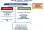
Contact relay diagnostics
To check the operation of the starter relay, you need to remove it from the mounting block and replace it with a known good one, or install a jumper. You can also try .

Using a jumper wire to test a contact relay
If, after replacing the contact relay, the car starter began to work, then the fault was in the “relay”. If, on the contrary, the replacement did not bring any results, then “the problem was not in the reel” and the old relay is most likely working.
Useful advice on what you can temporarily replace the starter relay with
If your starter relay breaks during a trip, you can replace it with a “heating relay rear window" They are identical. Number “rear window heating relay” K10.
The difference between the schemes in the Standard, Norm or Lux trim levels is insignificant, and is primarily due to the installation of additional equipment.
A total of 32 fuses are installed in the mounting block, which is slightly more than in older versions. Those of them that are located in the cabin are responsible for the operation of various circuits with relatively low power.
The security forces, as previously noted, were placed in engine compartment. This was done to ensure a greater level of safety and ease of maintenance of the vehicle.
The manufacturer expressly prohibits the use of protective devices during replacement that do not correspond to the nominal ratings of those indicated in the diagram. In particular, exceeding the maximum values leads to overload of the circuit and subsequent failure of the equipment powered by it. All this most often leads to fire.
It is important to remember that if a fuse blows, you should not change it immediately. First of all, you need to find out what exactly led to this. Otherwise, there is a risk of the insert melting on the new one.
If you do not have the knowledge to test electrical systems, you should seek the help of professionals.
How to replace fuses or relays
- F2 (30 amperes), in charge of power windows;
- F3 (15) – alarm;
- F4 (20) – wipers and airbag;
- F5 (7.5) – ignition switch;
- F6 (7.5) – reverse signal.
F7, rated at 7.5 amps, controls the circuit:
- adsorber valve;
- oxygen sensor;
- DMRV;
- speed sensor
- F8 (30) – rear view mirror heating;
- F9 (5) – right clearance;
- F10 (5) – left side signal;
- F11 (5) – rear fog lights;
- F12 and 13 (7.5) – are responsible for the low beam (right and left, respectively);
- F14 and 15 (10) for distant, in the same order;
- F16 and 17 (10) for front fog lights;
- F18 (15) – heated rear seats;
- F19 (10) – ABS;
F20 (15) protects:
- horn;
- luggage compartment locking mechanism;
- cigarette lighter;
- diagnostic connector.
In its turn:
- F21 (15) – fuel pump;
- F22 (15) – central locking;
- F23 (10) – daytime running signals;
- F24 (7.5) – air conditioning system;
- F25 (10) – interior lights and brake lights;
- F26 (25) – anti-lock brake.
From 27 to 30 – backup fuses.
F31 is rated at 50 amps and protects the heating system windshield. In turn, F32 is responsible for the heater and electric power steering.
In the engine compartment mounting block the location of the fuses is as follows:
- F1 – power steering (50 amperes);
- F2 – heater fan (30);
- F3 and 4 – generator (60);
- F5 – low beam (30).
Fuse- This electrical appliance, which serves to protect the electrical circuit in which it is directly installed. Almost all components of the Lada Granta car are protected by fuses except three, through which a very large current passes: the battery charging circuit, the generator and the engine starting circuit (starter).
Each circuit protected fuse characterized by the maximum current that can flow through it. Based on this indicator, a fuse for the appropriate current strength is installed in the break of this circuit with a small margin. If one of the circuit elements fails and the current exceeds permissible value for this circuit - the fuse will melt and de-energize this part scheme.
This ensures safety electrical wiring car and this also helps to avoid electrical fires in the event of a short circuit in any circuit.
The fuse box on the Lada Granta is located on the left side of the instrument panel.
Lada Grant fuses have slightly smaller dimensions than fuses previous models VAZ 2110-12, 2114-15. Also, their number has now been increased to 32.
Below is a description of each fuse and the circuits it protects on a Lada Granta car.
Location of the Lada Granta fuse box.
Fuse layout diagram in the Lada Granta mounting block.
Lada Granta fuse table and the car components they protect.
| Fuse | Current strength, A | Protected circuit |
|---|---|---|
| F1 | 15 | - Engine cooling fan relay - short circuit 2x2 - Controller (engine control unit) - Injectors - Ignition coil |
| F2 | 30 | Electric windows |
| F3 | 15 | Alarm |
| F4 | 20 | - Windshield wiper - Airbag |
| F5 | 7,5 | Ignition switch terminal 15 |
| F6 | 7,5 | Reversing light |
| F7 | 7,5 | - Canister valve - Sensor mass flow air - Oxygen sensor 1/2 - Speed sensor |
| F8 | 30 | Rear window defroster circuit |
| F9 | 5 | Side lights on starboard side |
| F10 | 5 | Side lights on the left side |
| F11 | 5 | Rear fog lights |
| F12 | 7,5 | Low beam on starboard side |
| F13 | 7,5 | Low beam on the left side |
| F14 | 10 | High beam on starboard side |
| F15 | 10 | High beam on the left side |
| F16 | 10 | Front anti-fog headlight starboard |
| F17 | 10 | Front fog lamp on the left side |
| F18 | 15 | Heated front seats |
| F19 | 10 | ABS (Anti-lock Braking System) |
| F20 | 15 | - Sound signaling device - Trunk lock - Transmission - Cigarette lighter - Diagnostic connector |
| F21 | 15 | Electric fuel pump |
| F22 | 15 | central locking |
| F23 | 10 | Daytime Running Lights |
| F24 | 7,5 | Air conditioner |
| F25 | 10 | - Interior lighting - Stop signal |
| F26 | 25 | Anti-lock braking system |
| F27 | - | Spare |
| F28 | - | Spare |
| F29 | - | Spare |
| F30 | - | Spare |
| F31 | 50 | Heated windshield |
| F32 | 30 | - Heater - Electric power steering |
Table describing the relays used in the Lada Granta mounting block.
| Relay | Description |
|---|---|
| K1 | Heater fan relay. |
| K2 | Power window relay |
| K3 | Starter relay |
| K4 | Ignition switch terminal 15 relay |
| K5 | Turn signal and hazard warning relay |
| K6 | Wiper relay |
| K7 | Relay high beam headlights |
| K8 | Horn relay |
| K9 | Low beam relay |
| K10 | Heated rear window relay |
| K11 | Controller relay (engine control unit) |
| K12 | Electric fuel pump relay |
In addition to the main fuses, the Lada Granta car has additional block power fuses, which is located in engine compartment. The cover of this block slides up and is removed.
Location of the power fuse box on the Lada Granta.
- Fuses located in the power fuse block Grants:
F1, 50A - Electric power steering;
F2, 30A - Heater fan
F3, 60A - Generator
F4, 60A - Generator
F5, 30A - Low beam headlights.
If you find that any fuse has burned out, do not rush to replace it with a new one. You must first ensure that the devices protected by this fuse are in working order. If the installed new fuse fails repeatedly, contact an auto electrician. Under no circumstances should you try to install a new fuse with a higher rated current in place of a repeatedly blown fuse. This can lead to fire and burnout of electrical wiring.
Majority electrical circuits V modern cars protected by fuses. Firstly, this protects the electrical device itself from damage, and secondly, it prevents the threat of fire due to overheating or short circuit.
We gain access to the fuse box in the cabin
In the Lada Granta, the fuse box, or as it is also popularly called, the mounting block, is located to the left of the driver. To gain access to it, you need to lower the protective decorative plug down.
Removing the decorative plug
Location of the latches of the decorative plug of the mounting block

Removed from one mount
For ease of use, I recommend completely removing the decorative plug and putting it aside. To do this, you need to remove the chip from the trunk opening button. The chip can be easily removed; there are no latches that hold the chip in place.

Remove the chip from the trunk button
Also, the chip is made for fools; you won’t be able to put it on incorrectly, so you don’t need to remember its seating position.
Removing fuses and contact relay
To replace (remove) fuses and contact relays, the mounting block is equipped with special tweezers. For fuses - small tweezers, for contact relays - large tweezers.
Fuse layout diagram in the mounting block
Mounting block diagram |
Fuse box (painted numbers all day) |


Clue. On back side decorative plug, there is a diagram of the location of fuses and a contact relay in the mounting block!
| Fuse no. | Current strength, A | Protected electrical circuits |
|---|---|---|
| F1 | 15 | Controller, engine cooling fan relay, short circuit 2x2, injectors |
| F2 | 30 | Window lifters |
| F3 | 15 | Emergency Signal |
| F4 | 20 | Windshield wiper, airbag |
| F5 | 7.5 | 15 terminal |
| F6 | 7.5 | Reversing light |
| F7 | 7.5 | Canister valve, mass air flow sensor, DC1/2, speed sensor |
| F8 | 30 | Heated rear window |
| F9 | 5 | Side light right |
| F10 | 5 | Side light left |
| F11 | 5 | Rear fog light |
| F12 | 7.5 | Low beam right |
| F13 | 7.5 | Low beam left |
| F14 | 10 | High beam right |
| F15 | 10 | High beam left |
| F16 | - | - |
| F17 | - | - |
| F18 | - | - |
| F19 | - | - |
| F20 | 15 | Horn, trunk lock, gearbox, cigarette lighter, diagnostic connector |
| F21 | 15 | Gasoline pump |
| F22 | 15 | central locking |
| F23 | 10 | DRL |
| F24 | - | - |
| F25 | 10 | Interior lighting, brake light |
| F26 | - | - |
| F27 | - | - |
| F28 | - | - |
| F29 | - | - |
| F30 | - | - |
| F31 | - | - |
| F32 | 30 | Heater, EUR |
Contact relay diagram
| Relay | Description |
|---|---|
| K1 | Heater fan relay. |
| K2 | Power window relay |
| K3 | Starter relay |
| K4 | Ignition switch terminal 15 relay |
| K5 | Turn signal and hazard warning relay |
| K6 | Wiper relay |
| K7 | High beam relay |
| K8 | Horn relay |
| K9 | Low beam relay |
| K10 | Heated rear window relay |
| K11 | Controller relay (engine control unit) |
| K12 | Electric fuel pump relay |
Difference in trim levels: , standard, luxury
The mounting block is the same for all vehicle configurations: standard, normal, luxury. Depending on the configuration and equipment of the vehicle, some relays may be missing from the fuse block.
New fuse box

New fuse box

New fuse box diagram
Fuse box under the hood of a car
In the Lada Granta car there is another block of “powerful” fuses under the hood of the car. Fuse ratings range from 30A to 60A, so this block called power.

The fuse box is indicated by an arrow
To access the fuses, you must pull protective cover up. It can be easily removed. After finishing work, do not forget to return the cover to its place.
Block diagram in configurations: Standard, Norma
| Fuse no. | Denomination, A | Description |
|---|---|---|
| F1 | 30 | Low beam headlights or main relay, circuits protected by fuses F1 and F21 of the mounting block in the passenger compartment |
| F2 | 60 | Generator |
| F3 | 60 | Generator |
| F4 | 30 | Heater fan (heater fuse grants) |
| F5 | 50 | Electric power steering |
Block diagram in the Lux configuration
| Fuse no. | Denomination | Description |
|---|---|---|
| F1 | 50A | Heated windshield |
| F2 | 60A | Generator |
| F3 | 60A | Generator |
| F4 | 40A (in configuration without air conditioning system- 30A) | Electric radiator cooling fans |
| F5 | 50A | Electromechanical amplifier steering |
| F6 | 40A | Anti-lock brake system (ABS) control unit |
If the fuse constantly blows, then this is a reason to think about proper operation this chain. We also do not recommend making changes to the design unless absolutely necessary.
New car Lada Granta (VAZ 2190) was released in 2011 to replace three VAZ cars - 2107, Samara and Kalina. Lada Granta is built on the AvtoVAZ Kalina platform and is a budget option. Granta is available in three trim levels - Standard, Normal and Luxury. The luxury version includes full power accessories, air conditioning, two airbags, heated mirrors and front seats, ABS+BAS.
Fuse box- located to the left of the steering column on the instrument panel. To access you need to remove the cover (with latches). Power fuse block- located under the hood.
Mounting block VAZ 2190

Location of fuses and relays

Lada Granta fuse table and protected circuits
| F1(15A) | The engine control unit. Engine cooling fan relay. Injectors. Ignition coil. |
|---|---|
| F2(30A) | Electric windows. |
| F3(15A) | Alarm. |
| F4(20A) | Windshield wiper. Airbag. |
| F5(7.5A) | Terminal "15" of the ignition switch. |
| F6(7.5A) | Reversing light. |
| F7(7.5A) | Canister valve. Mass air flow sensor. Oxygen sensors. Speed sensor. |
| F8(30A) | Rear window defroster circuit. |
| F9(5A) | Side lights on the starboard side. |
| F10(5A) | Side lights on the left side. |
| F11(5A) | Rear fog lights. |
| F12(7.5A) | Low beam (starboard side). |
| F13(7.5A) | Low beam (left side). |
| F14(10A) | High beam (starboard side). |
| F15(10A) | High beam (left side). |
| F16(10A) | Front fog lamp (right). |
| F17(10A) | Front fog lamp (left). |
| F18(15A) | Heated front seats. |
| F19(10A) | ABS ( anti-lock braking system brakes). |
| F20(15A) | Sound signal. Trunk lock. Cigarette lighter. Diagnostic connector. Checkpoint. |
| F21(15A) | Electric fuel pump. |
| F22(15A) | Central locking. |
| F23(10A) | Daytime Running Lights. |
| F24(7.5A) | Air conditioner. |
| F25(10A) | Interior lighting. Stop signal. |
| F26(25A) | ABS. |
| F27-F30 | Reserve. |
| F31(50A) | Heated windshield. |
| F32(30A) | Heater. Electric power steering. |
Power fuse block (Normal)