The electric sewing drive of any industrial machine has not only a different speed control design (clutch), but also a different electrical diagram, the principle of operation of the electric motor.
Household models of electric drives have low power from 40 to 110 watts, low rotation speed and asynchronous motor operation. In other words, a household electric motor cannot withstand large and long-term loads and requires periodic “breathing”. Sewing motor An industrial machine can work for days without a break, without overheating or losing speed.
If you need a machine for mass sewing, then immediately think about the good suitable drive. You can buy inexpensive used tables with motors from advertisements. Soviet issue. These are reliable and efficient electric drives, and perhaps these are the ones you should use. But keep in mind that they all work very noisily, and no amount of adjustment can eliminate this noise. Therefore, we recommend purchasing immediately good drive, for example, the table and drive included with the Typical sewing machine. And just like that sewing electric drive We will look at it in detail in this article.

The Typical electric sewing drive can be purchased separately and installed on any industrial table, but it is better to purchase it complete with a table, especially since the table itself is cheaper than the motor.
By the way, you can also buy a convenient sewing table for a household sewing machine. A comfortable spacious table, and at the same time a cutting sewing table will make your work more comfortable, which will definitely affect your mood and, accordingly, the quality of your work. If you have the opportunity and you have to sew a lot, never neglect such “little things”.

Even such an insignificant detail as an electric drive switch creates comfort at work and affects your mood.
Electric motor power and mains voltage

On front side There is a label on the motor that indicates the mains voltage and motor power.
If you are going to install the machine at home or in a small studio where there is no 380-volt outlet, choose an electric motor to operate on a 220-volt network.
And the engine power in this example does not really matter, since the speed of the machine depends on other factors. We'll talk about this below.

What's happened friction drive? If you drive a car yourself, then you should know what a clutch is. So the clutch of an electric sewing drive is designed in a similar way.
The motor rotates constantly at the same speed. When you press the pedal, the friction device disk (ferado) with textolite linings approaches the motor flywheel and interacts with it. The tighter you press the clutch disc against the flywheel of the electric motor, the better their grip and the higher the speed. Therefore, sometimes from long work at slow speed and the smell of burnt PCB appears.
Degree freewheel(without force) the drive pedal is adjusted with this thumbscrew.

But with these screws, or rather two screws (with reverse side one more) the brakes are adjustable. Yes, exactly the brakes, almost like a car.
If you work for high speed, then after stopping the sewing machine by inertia, it will continue to rotate. Therefore, we need a brake that will immediately stop unnecessary rotation. It is with this screw and locknut that the degree of “sharpness” of the brake is adjusted.
We did not post a photo of the engine clutch design; engine repairs should be carried out by an electrician, but you need to be able to regulate its operation with your own hands.

It is better to adjust the lift height or pedal angle here.
What determines the speed of an industrial sewing machine?

The operating speed of an industrial sewing machine depends primarily on the speed of the electric motor. This parameter can be found on the tag or in the drive passport. But such details are of interest only to specialists in factory tailoring. For small manufacturers, this parameter of engine operation is secondary, since there is another way to adjust the speed of an industrial sewing machine.

Namely, by changing the engine pulley. The larger the pulley diameter, the higher the maximum operating speed of the sewing machine.
Changing the pulley is not at all difficult; for this you need a 19mm wrench and the pulley itself, which is usually included with the engine. But keep in mind that you will have to adjust the length of the drive belt, and in many cases it will have to be of a different diameter.

No matter how good an industrial drive may be, even one as modern, almost silent and beautiful as that of Typical, it is not always needed. This applies to home-based seamstresses. They often work at home in industrial sewing machines Oh, such as 1022 class, 97 class. For various reasons, but primarily due to increased operating noise, they cannot use them.
To solve this problem simply and inexpensively, buy a TUR-2 electric drive and install it directly on the body of an industrial machine. We will not explain how to install; in each case you have to use your own solution. But we can advise, if necessary, to solder the wires instead of the plug as shown in the photo.
In addition, if the position of the windings of such an engine is reversed, the engine will rotate in the other direction. This advice will come in handy when connecting an overlocker to such a drive.
But all these tips are intended only for electricians; we strongly advise against amateurs disassembling the engine themselves, much less changing or soldering anything. There is not only a direct danger of electric shock, but also a hidden one. It appears after a long time. Overheating of the motor windings, even when the sewing machine is not working but connected to the network, can cause the windings to ignite.
Other brands of electric motors can also be installed on industrial machines, but we recommend only what we have tested, namely the TUR-2 electric drive.
And do not forget that the speed of the machine is noticeably reduced and you can only sew on it for a short time, taking long breaks (pauses).
Sometimes it becomes necessary to disassemble the sewing machine, or rather remove the plastic body of the machine in order to gain access to some components. Such a need arises very rarely and it arises only when it is necessary to replace the sewing machine motor or drive belt. However, to replace the electric drive, sometimes it is enough to remove only the bottom and side covers. But to eliminate the “jamming” you will have to disassemble the machine completely.
In this article you will learn how to find the cause of an electric drive malfunction, as well as how to replace the electric motor yourself.
Usually, problems with an electric sewing drive start with the pedal, not with the electric motor. However, we do not recommend disassembling the pedal yourself. Handle the pedal with care, do not twist the wires, do not “stand” on them with a chair leg, and generally remember what passes through these wires electricity, voltage 220 volts.

Manual sewing machine - drive design and repair
Sewing manual typewriter Simply irreplaceable when sewing thick fabrics and even leather. But here manual drive so inconvenient that there is no desire to use it. However, this situation can be easily corrected if you buy an electric sewing drive along with a pedal and drive belt included. Each electric motor has standard mount, which allows it to be installed even on a manual sewing machine.
The foot drive of a sewing machine is more of a museum piece these days. It rattles, knocks, and your legs get tired. In addition, the machine often starts spinning in the wrong direction. How to refuse to use it if the Chaika or Podolskaya machine suits you perfectly? You just need to install the electric sewing drive. Every Chaika has a mount for it. The electric drive itself costs only twice as much as a new foot drive belt.
The zigzag attachment for a sewing machine is a clever device that simulates the execution of a zigzag stitch with a conventional Podolsk-type lock-stitch machine.
In this article you will learn why a machine with a horizontal shuttle loops and how to fix this sewing stitch defect with your own hands.
The sewing machine will not sew if the flywheel friction washer is installed incorrectly or if the bushings, etc., have rusted during long-term storage.
Each model of household sewing machine has its own set of feet. Detailed description using paws for household sewing machines from Janome.
To work with genuine leather you need special tools, devices for installing fittings, adhesives and other applied materials.


 Materials and tools:
- Soldering Station
- wire solder 60/40 1mm
- soldering clamp
- 10 AWG wires (about a meter)
- 4mm bullet connector (“male” - 6 pcs, “female” - 4 pcs)
- stripper
- heat shrink tube 5mm-15cm, 15mm-8cm (red and black)
- wire cutters
- heat gun
- copper ring 15mm - 2 pcs
- insulating tape
- pliers/crimpers
- multimeter
Preparing the wires
As you can see in the photo, I used a wire in black insulation, but you can use 50cm of red and black wires to indicate the polarity of the connection.
The wire is cut into five 10cm sections, the ends of which are stripped on one side by 4mm, on the other by 15mm. Four wires (of the same color) are twisted together with 15mm ends, and then a fifth wire is added to this twist, but going in a different direction.
A copper ring is put on the twist and crimped pliers or crimping pliers.
The resulting cable is checked for breaking using a multimeter, which is set to “sound” mode, the first probe is applied to a single contact of the cable, and the second is applied in turn to each of the four contacts, and if there is no circuit, the ring is crimped tighter or soldered with solder until a connection is obtained between contacts.
Next, the twist is wrapped with electrical tape, and then a piece of 15x40mm heat-shrink tubing is put on it (red for the positive wire, black for the negative) and “shrinked” using a heat gun for better insulation.
The same operations are performed to obtain the second brain cable .
Soldering the positive cable (red)
The stripped end of the single wire of the cable is twisted and inserted into the male connector. Next, it is installed in the solder clamp so that the wire is horizontal and the solder hole in the connector is facing up. At the soldering station it is set heat, since you need to warm up the connector and wire well so that the solder melts.
The heated tip of the soldering iron is placed to the connector under the soldering hole, next to the entry point of the 10 AWG wire, everything heats up for some time (do not touch the heated parts), and then, still holding the soldering iron at the connector, it is fed into the soldering hole solder until it flows down the wire. After this, the soldering iron is removed from the soldered parts, and they are given some time to cool.
The entire procedure is repeated for the remaining four cable wires and male connectors.
After this, the quality of the soldering is checked with a multimeter, five pieces of 5x30mm red heat-shrinkable tubing are cut off and placed at the junction of the wires and connectors, and then they are grabbed with a heat gun to insulate the connections.
Soldering negative cable (black)
For the negative cable, all the same procedures are repeated as for the positive one, only the connectors are female, and the heat-shrink tube is black.
Note: It is recommended to use 10mm heat shrink tubing to insulate all open parts of the connectors, this will avoid short circuits when connecting/disconnecting batteries to charge them.
Step 9: Toggle Switch and Motor Cables


Materials and tools:
- Soldering Station
- wire solder 60/40 1mm
- soldering clamp
- 2 meters of black 10 AWG wire
- 4mm bullet connector - 4 pcs.
- flat female terminal 6.35mm - 2 pcs
- black heat shrink tube (5mm -3cm, 15mm - 60cm)
- red heat shrink tube (5mm - 20cm, 15mm - 4cm)
- toggle switch
- stripper
- wire cutters
- heat gun
- insulating tape
- multimeter
Power button cable
The ends of two 50cm black 10 AWG wires are stripped of 4mm of insulation and a 6.35mm flat terminal is attached to one end of each wire. Next, a “male” connector is soldered to the free end of one wire, and a “female” connector is soldered to the other wire. And the quality is checked using a multimeter brain connections.
Pieces of red 5x30mm heat-shrinkable tubing are “shrunk” onto the resulting terminal-wire connections, then the wires are connected to the terminals of the toggle switch and again the quality of the contacts and the performance of the toggle switch itself are checked with a multimeter. If the multimeter shows a break, then you need to check how tight the terminals are, this can be seen directly, and if everything is fine, then the contacts are insulated with electrical tape and a piece of 15x40mm red thermal tube. After this, a large piece of black heat-shrinkable tubing 15x400mm is cut off, put on both wires leading to the toggle switch, and “shrinked” with a heat-shrink gun to obtain a neat cable.
Motor cable
One of the wires on this cable can be replaced with 10 AWG red wire to indicate polarity.
Each end of three 26cm x 10 AWG wires is stripped 4mm, then a male connector is soldered to one end of each wire and a female connector is soldered to the other.
Next, two pieces of 5x30mm black heat-shrinkable tubing are cut off and the connections of one of the wires (black) are insulated with them. Two pieces of 5x30mm red thermal tube are cut off and the connections of the second wire (yellow) are insulated with them. And then two more pieces of 5x40mm red heat-shrink tubing are cut and they are “shrunk” onto the connections of the third wire (red). Finally, a piece of 15x200mm black thermal tubing is cut and placed over all three wires, and then “shrinked”, thereby forming a neat motor cable.
Note:
After connecting the motor, it may not rotate in the desired direction, and to fix this, just swap two wires with red insulation. You can also immediately mark the “yellow” wire, for example, with yellow electrical tape, and in the future, when connecting the engine, you do not have to worry about the correctness of this connection.
For insulating all exposed connector areas homemade products It is recommended to use 10mm heat shrink tubing to avoid short circuits when connecting/disconnecting contacts.
Step 10: Speed Controller, Servo Tester Modification and Throttle Switch


 Materials and tools:
- speed controller HobbyKing 85A Blue Series Brushless Speed Controller 5A SBEC
- Etronix 3 Mode Servo and ESC Tester
- "finger" throttle switch
- Soldering Station
- wire solder 60/40 1mm
- soldering clamp
- "female" connector "bullet" 4mm - 5 pcs.
- black heat shrink tube 5x60mm
- red heat shrink tube 5x60mm
- stripper
- wire cutters
- heat gun
- insulating tape
Speed controller. Battery connection side
To speed controller contacts crafts, going to the batteries, two 4mm “female” connectors are soldered using a soldering clamp. Next, pieces of 5x30mm red and black heat-shrinkable tubing are cut and put on the corresponding contacts of the speed controller, and then “shrinked” with a heat-shrink gun.
Speed controller. Motor connection side
Using a soldering clamp, three “female” connectors (three black wires) are soldered to the contacts of the speed controller going to the batteries, then one piece of 5x30mm black heat-shrink tubing and two pieces of 5x30mm red heat-shrinkable tubing are cut off.
Note:
It is necessary to decide on the motor contacts before putting heat-shrink tubes on them, and when this is done, the contacts are marked with tubes and “shrinked” with a heat-shrink gun.
All open places brain connectors should be insulated with a 10mm thermal tube to avoid short circuits.
Refinement of the servo tester
When using a motor and speed controller, the throttle must be adjusted in some way, and often a transceiver used in radio simulation is suitable for this.
In this crafts no plans to use the block wireless communication, this uses a servo tester connected to a thumb-controlled throttle switch.
The handle is removed from the potentiometer shaft and the shell of the servotester is “opened”, then the potentiometer itself is unsoldered from the board, and a jumper is soldered in its place between the two terminals (see photo). The board is placed back into the shell and secured with electrical tape, leaving only 3-pin connectors free - one for the throttle, the other for the speed controller (see photo).
Throttle switch
First, determine the purpose of the wires and the type of switch connector brain games.
You need to make sure that the wires are arranged in the following order: black, red and one more of any color (see photo), it can be blue, as in the photo, or white, or something else.
You can solder them directly to the board, or you can use a 3-pin JR connector (see photo) and, if necessary, turn off the throttle switch.
Step 11: Friction Drive Assembly


 Materials and tools:
- brushless motor C6374/08 KV200
- motor support assembly
- nylon bracket
- spring
- spring tension bushing
- 8mm wrench
- M4x20 bolt with cylindrical head - 4 pcs.
- M5x20 bolt with external thread - 2 pcs.
- nut M5 - 2 pcs
- M8x40 bolt with cylindrical head - 2 pcs.
- M4x8 bolt with external thread - 2 pcs.
- dry teflon bicycle lubricant
- hex keys 2, 2.5, 3 and 6mm (preferably with a long rounded end)
Assembly
Build process brain games It begins by screwing two M5x20 bolts into the nylon bracket, so that they do not protrude into the cavity of the segment, but are flush with it, then M5 nuts are loosely screwed onto the bolts. Then a spring is inserted into the hole on the other side of the bracket with the short end inward (see photo).
Bicycle lubricant is applied to the rolling axis and it is inserted into the hole in the bracket from the side with the selected segment. The nylon bracket is slightly raised above the aluminum caliper so that the long end of the spring rises above the rolling axis, this will allow you to insert the end of the spring into the 2mm hole of the spring tension sleeve, which is put on with the drilled side to the nylon bracket, and then everything slides back to the caliper (see photo ).
After that brainspring tensioned by rotating the bushing ¼-1/2 turn counterclockwise until the corresponding hole in the rolling axis is found, and then the M4 bolts of the tension bushing are tightened with a 2mm hexagon.
Using M4x20 bolts with a cylindrical head and four holes in the caliper, the engine is attached to it, taking into account the location of its wires (see photo). Not necessary, but at this stage you can screw the second part of the bracket using M8 bolts with a cylindrical head.
Note:
Do not over-tighten the spring, as this may bend the end of the spring and tear it out of the 2mm hole.
Step 12: Mounting the Clutch on the Bicycle


 Materials and tools:
- clutch assembly
- flat bar (metal ruler or long block)
- 8mm wrench
- hexagons 2.5 and 6mm
- roulette
Attaching the clutch to the frame
Friction homemade is applied to the tube under the seat so that in the “inactive” position the engine is located at a distance of 10mm from the tire and the washers of the M8 bolts are slightly tightened to be able to align the edge of the engine parallel to the wheel axis (see photo). After this, the M8 bolts are tightened evenly by more than half a turn so that the clutch does not rotate on the frame tube.
Next, the engine is pulled up with a little effort until it rests against the wheel. Using a flat bar (metal ruler), which is applied to the rolling axis and the wheel axis, the position of the engine is set so that its center “lies” on the bar (ruler) (see photo).
Having achieved this, tighten the lower one with a 2.5mm hexagon adjusting bolt, while the center of the engine shaft should be directly on the line between the axes, or slightly below it. I have found that when set correctly the motor will simply rest on the tire and disengage from the wheel with minimal force.
Having found a good one brain state From the engine, use an 8mm wrench to tighten the nut of the adjusting bolt. It may be easier to do this on the other side of the bike and with the engine pulled out, this little trick will make it easier to “throw on” the wrench. (I believe that the corresponding section will need to be milled out in the support of the next craft).
After this, the engine position is set to “inactive” mode. To do this, the upper adjusting bolt is tightened until the engine “comes off” from the tire by 5 mm, having achieved this, the bolt is fixed with a lock nut (see photo).
Note:
After complete installation frictional homemade products you can indicate its position by wrapping the bicycle frame with electrical tape at the top and bottom of the bracket several times, and refer to these marks if you need to remove the friction brain trick.
Step 13: Connecting the Friction Drive


 Materials and tools:
- clamps
- pliers/cutters
- hex keys
- throttle switch
- on/off toggle switch
- connecting cables
- modified servo tester
- bag for batteries (Topeak Aero Wedge Pack)
- speed controller (HobbyKing 85A Blue Series Brushless Speed Controller 5A SBEC)
- two rechargeable batteries (Turnigy 5000mAh 5S 20C Lipo Pack)
Connecting cables
The throttle switch is attached to the bicycle handlebar in a convenient place, and the cable coming from it is attached along the frame and under the seat using zip ties (see photo).
A cable is connected to the speed controller, going from it to the engine, and the speed controller itself is attached on top of the battery bag, then this brainbag hangs on a bicycle (see photo), the cable from the controller is connected to the engine.
The on/off switch is installed under the seat, the cable coming from it is attached to the frame with zip ties, then one of its wires is connected to the “red” wire on the “power side” of the speed controller (see photo). The throttle switch cable connects to the servo tester, which is located under the seat, and the thin speed controller cable connects to the back of the servo tester (see photo).
Next to two batteries homemade products the appropriate cables are connected, and the batteries themselves are placed in the “battery” bag as deep as possible. The “red” positive wire coming from the batteries is connected to the on/off switch, and the “black” negative wire is connected to the corresponding contact on the “power side” of the speed controller.
All that remains is to fasten the “battery” bag and craft ready!
Basic throttle calibration with speed controller (first start)
After studying the instructions for the speed controller and adjusting the throttle, you need to ensure that the throttle switch works correctly.
For used in this brain work speed controller, the first thing you need to do is move the throttle switch to the “maximum” position and lock it in it, after that, by applying voltage to the system by pressing the on/off toggle switch, the speed controller will emit several short beeps, then the throttle switch is moved to the “ minimum" and is again fixed there, before the controller gives another sound signal, which will mean that the calibration is completed, and after that the on/off toggle switch turns off the entire system. That's all there is to it.
Note:
Do not touch the throttle switch when turning on the power while the controller homemade products serves sound signals, unless the controller is being calibrated.
Step 14: Friction Drive in Action

 It should be remembered that the friction drive in this version is designed only as additional element, and should not be started while not driving, as this may cause engine damage.
I will activate this homemade at a speed of at least 22 km/h, while I keep the throttle switch in the middle position, or at the “maximum” position, but for 3-4 seconds, and then release it.
On this moment I only use two Turnigy 5000mAh 5S 20C Lipo Packs out of the four available in this design, and they last me 19.3km on my round trip.
That's all, I hope it was cerebral!
Requirements for the drive of sewing machines.
Topic: Electric drive for sewing machines.
Lecture 7.
On sewing machines, the drive operates in an unusual manner. difficult conditions when within an hour
Up to 1000 machine starts are made. Is there another technological machine with a similar mode of operation? And the speed of the main shaft is up to 9000 rpm! Many gears cannot handle such speeds! Hence the special requirements for the electric drive:
1. Speed – the ability to provide (5 – 6) 10 3 min –1 on the main shaft of the machine.
2. Must withstand up to 1000 on-off switches per hour.
3. Smooth start, smooth adjustment of machine speed.
4. Drive control - pedal with maximum pressing force - 60 N while standing, and sitting up to 150 N.
5. Have a high K, P, D (in the workshop it becomes unnecessarily hot from many closely located welding machines), conveniently located (do not interfere with the operator’s ability to sit freely), and safe to operate both electrically and mechanically.
6. The cost of the electric drive should not be a subject of much discussion. (Automated electric drives have over 30 microcircuits, and their cost is equivalent to the cost of a machine head!)
In the sewing industry, mainly three types of electric drives are used, depending on the type and purpose of the technological machine:
· Contactor– when by turning the switch or pressing the pedal the car immediately picks up the rated speed. Smooth starting and speed control are not required. The drive is used on low-speed, simple-to-use machines that are rarely turned off (rewinding fabric, duplicating it, etc.)
· Friction– when a pedal-controlled friction clutch is installed between a simple asynchronous electric motor and a V-belt drive, ensuring smooth start and smooth speed control while the machine is moving. Today it is most widely used on both universal and special machines.
· Automated electric drive Allows you to program the operation of the machine, automatically perform basic and auxiliary operations of the technological cycle. Expensive and complicated, low efficiency. There is a tendency to replace it with a simple, well-speed controlled DC motor.
Figure 5 shows the block diagram friction clutch friction electric drive of a sewing machine, which is marked:
1. Shaft asynchronous electric motor,
2. The drive disk, fixedly fixed at the end of this shaft, without ring linings, is made of steel,
The driven disk has ring linings on both sides made of high-friction wear-resistant material.
The disk is fixed to shaft 6 of the friction clutch.
3. The brake disc is stationary, often floating, i.e. Its plane self-aligns into the plane of disc 3 upon contact with it.
4. The compression spring tends to move shaft 6 together with disk 3 to the right until it comes into contact with disk 4.
5. Clutch shaft; a fixed fit with the left ball bearing of the sleeve 7 and a movable fit with the right one.
6. Horizontally movable inner sleeve. It moves left and right in the coupling body together with shaft 6.
7. Pulley V-belt drive, presenter. On old ones industrial machines two pulleys were installed - the smaller one (item 9 not shown) - for running in a new or old car from repair; a reduction in machine speed of » 25% was achieved.
10. Roller in the groove of the movable sleeve.
11. Double lever.
12. Adjustable length rod.
13. Start pedal.
14. The coupling body, consisting of two parts (the division is not shown in the diagram).
15 . Machine industrial table.
16. A plate to which the coupling body assembly is hinged from below. There is a set screw in the hinge; serves to fix the coupling body in the desired position for correct tension V-belt transmission.
If you choose transport between a car, a motorcycle, a bus or a bicycle, then, probably, many will choose the last option. If you think about it, this is the most convenient and quick way movement. Since a car is quite an expensive thing, and it will take a very long time to get anywhere with it due to eternal traffic jams, a bus is also not an option - you will have to huddle among a crowd of people, among whom it is very hot and uncomfortable.
A motorcycle is a must have driver's license and besides, riding it can be dangerous. Therefore, all that remains is a bicycle, which, if equipped with an engine, will be ideal vehicle. This means of transportation has become very popular in last years. Even a simple old grandfather’s bicycle can be equipped with a motor and easily move around the city, quickly and without traffic jams. You can choose at your discretion.
Types of electric motors
 The following types of electric motors can be installed on a bicycle:
- Motor-wheel;
- Motor on friction gear;
- Suspension type electric motor.
The most popular manufacturers of electric motors

1. Bafang (8FUN)– electric motor made in China.
This company produces electric motors in the form of a set with a wheel. This motor is suitable for secure connection to any frame. Power of this manufacturer engines vary - its range ranges from 250 W to 750 W. The voltage will also be different - from 24 to 48 V. Of all the electric motors from this manufacturer, the motor whose power is 750 W 29 A is different.
The gearbox in it has two gear stages. The set includes a drive unit, gas pedals, connecting rods, a monitor and a brake pedal. The total mass of the entire electric motor is only about four kilograms. The speed to which the motor can accelerate maximum is only 50 km/h. 
2. Bosch.
Companies such as Merida, Scott, Stevens, Cannondale use these engines to produce their bicycles. The acceleration speed of such an electric motor is not very high - only 25 km/h. Its power is approximately 250 W, and the maximum value can rise to 350 W.
These electric motors are also available in a set that includes:
- A mechanism that signals that the motor needs to be assisted by pedals.
- A device that fully charges a battery in three hours
- A computer that is equipped with four modes. This computer allows you to economically use battery consumption by adjusting engine power in the desired proportion.
The weight of such an electric motor is only 2.5 kg, which is very convenient when riding, as the bike becomes heavier.
3. Golden Motor. These motors are presented in the form of a wheel. The kit includes a gas pedal, battery and other components for mounting the engine. Most high level The voltage of such a motor is 60V. The engine itself includes a sensor that signals the load level and temperature. Maximum speed The speed that a bicycle equipped with this type of engine can reach is 40 km/h. Its weight is relatively small - only three kilograms. You can mount such a motor on almost any bicycle.
4. YAMAHA electric motor this is very famous name a brand that even produces bicycle engines. Here the main advantage is considered to be high technical indicators and the quality of the engine itself. The power of this type of motor can reach 4 hp. Here you no longer have to help the motor with pedals when going uphill.
The disadvantages include Very high cost of this item. This company increasingly began to produce engines for bicycles of an electronic nature, therefore gasoline types the engine is getting smaller.
Motorcycle kits for bicycles
Wheel motor
 This type of engine has become very popular among bicycle enthusiasts. Its main advantage is the ability to convert a simple bicycle into an electric bicycle.
It should be noted that when mounting this engine into a bicycle, it is practically invisible, since the motor is a wheel in design and appearance looks like a simple hub.
This engine can be installed either on one of the wheels or on both wheels at once.
Once the installation of the battery and throttle lever is completed, the bike is ready for use. The power of this type of motor ranges from 150 W to 2000 W.
Depending on the power, a motor with a certain voltage is selected - from 24 to 48 V. For each of these options, it is necessary to select the right battery.
This type of engine is capable of reaching speeds of up to 70 km/h, and at this speed can travel approximately 50-60 km. But when moving uphill, these indicators may change.
 Outboard motor
Such a motor is an independent part that is connected to the lower part of the bicycle frame. When installing this type of engine, be sure to install a casing that will protect the motor. While driving, the motor sends force through the chain to the rear sprocket of the bicycle.
The engine is powered by a battery, which is also mounted on the bicycle frame. Thanks to the controller, it is possible to regulate the speed and power of the engine. This controller looks the same as the gas lever on the steering wheel.
The outboard motor is a little heavier than the motor above, so the "upgraded" bike will be a little heavier.
 But this drawback is compensated by the fact that a bicycle with such a motor can reach speeds of up to 120 km/h. Bicycles that can be equipped with suspension can be very different. Friction gear motor
- The operating principle of this type of electric motor is that the torque transmitted from the electric motor is sent directly to the bicycle wheel, or more precisely to its tire.
- Such transmission is considered ineffective and has many disadvantages, such as:
- Low level of efficiency;
- Wheels last a very short time;
It is necessary to periodically check the air pressure in your bicycle tire;
In rainy weather, the torque transfer roller slips.
 The advantage of this type of electric motor is the ability to mount it on a bicycle without disassembling it.
If the electric motor is installed on , the torque will be transmitted to the front sprocket of the bicycle.
The set may be different types. Engine power varies from one to two Horse power. Most powerful engine can accelerate to 50 km/h.
A gas tank and muffler may also be included in the kit. The total mass of such an electric motor will be no more than five kilograms.
But such motors also have disadvantages. For example:
- An electric motor of this modification is relatively expensive;
- The quality of the motor is somewhat questionable;
- The aesthetic characteristics of the electric motor are also not ideal.
ICE Kits
Two-stroke engine with one cylinder
 This engine is mounted on a bicycle frame. Its torque is transmitted to the front wheel sprocket. The advantage of this transmission is that you can switch the speed of the electric motor.
Here it is necessary to use a special gasoline-meat liquid, which is working mixture. The motor is cooled by air flows. His maximum power is 1.5 hp. This is a lot for a bicycle, so you can safely ride on a straight road. But when driving uphill, you should help the motor with the pedals.
The maximum speed it can reach this engine– 30 km/h. For 100 km of road, the engine consumes one liter of fuel mixture.
The engine also comes with a muffler and gas tank. With this kit you can transform your old bike into a new fast bike.
Two-stroke gas motor for bicycle
This type of engine was invented Chinese manufacturers. Its volume is 48 cm3. Its difference from a simple electric motor is that it is mounted in place of the gas tank. gas cylinder. The entire design of such a motor is questionable. Such an engine does not save anything, since gasoline engines also consume little fuel.
Making an electric motor for a bicycle yourself
To improve your old bike yourself, you need to choose the right engine for his new assignment. Since all electric motors are charged from the network, you need to provide them with a battery of the required power. Sometimes they can reach impressive sizes, which is not always convenient and looks beautiful on a bicycle.
The most popular engine used to improve a bicycle is considered to be a motor from an old lawn mower or trimmer. You should take into account the power of the motor, because if it is weak, the bike will not even move. But one that is too powerful will not work, since it will have large dimensions.
Motors for a bicycle can be chosen completely different. You just have to take into account three parameters: weight, power, size.
How to make an electric bike yourself?
The sequence of manufacturing a bicycle with an electric motor:
- First of all, you need to purchase all the components of the electric motor: the engine itself, the controller, batteries, servo tester, Charger, necessary wires, alternator belts, freewheels, bushings, chain, sprocket, gear shifter, screws, nuts and much more.
- Next, assembly begins.
- Attach the sprocket to the bushing using a diamond blade.
- The teeth on the chain must first be ground and secured to a bushing with a diameter of 1 cm.
- The freewheel is connected to the chain and sprocket.
- The entire structure must be very strong, since traffic safety depends on it.
- It is necessary to ensure that the rotational movements from the motor to the sprocket are transmitted gradually so that there is no deformation of any parts of the mechanism. For this purpose, generator pulleys and belts are used.
- It is advisable to place a stainless steel plate on the frame, lubricated with thermal paste, onto which the controller is attached.
- A servo tester is necessary to regulate motor power. It should be powered using a special microcircuit.
- If desired, you can install a wattmeter. With its help you can control energy consumption.
- IN luggage compartment It’s worth coming up with a place to mount the batteries.
How to install an outboard electric motor for a bicycle yourself?
 You can install the electric motor yourself without the help of a specialist. The main thing is to choose the right engine.
Only knowing all the characteristics of the motor and the rules for connecting it to the battery and circuit can you cope with the task.
Operating procedure:
- The chain must be removed and one side connected to the engine shaft.
- Engine with battery can be connected using powerful wires.
- It is better to mount the battery and motor somewhere in the center of the bike. This is done using clamps, clamps and other fasteners.
- The power button should be extended to the steering wheel and securely fastened there.
E-bikes have many benefits that regular bikes don't have. There is no need to constantly turn the pedals; they are very maneuverable and quite environmentally friendly. You can make them yourself from an old unwanted bicycle, and it will last for many years.
Good quality electric motors do not require special complex care, the main thing is to ensure that moisture does not get into it. Every cycling enthusiast, be it a traveler or an athlete, will appreciate all the delights of an improved bicycle that does not require any effort to ride.
Rating: 4.1 12 votes
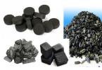
What could be simpler than a roller mounted directly on the engine crankshaft and pressed against the wheel tire? Until now, nothing simpler and more reliable has been invented. The friction drive was used in German bicycle motors, and in the iconic Velosolex moped, and in the domestic bicycle engine"Irtysh":
Even Ducati did not disdain to use a friction drive at the dawn of engine construction. Even Ernesto Guevara himself made an impressive journey on a bike powered by a Ducati Cucciolo.

The wave of abundance of used motors from lawn mowers has not yet reached us, but in America only the lazy does not build his own motorbike from an old trimmer motor and a bicycle pegs. Most often, such designs don’t even have a clutch - you push off with your foot, start the engine and go! IN best case scenario DIYers install a spring that presses the motor with the roller to the wheel.

Of course, simplicity of design plays an important role in the motorcycle industry, but do not forget that modern engines they have stepped far forward in their design and there is no need to give up such conveniences as automatic centrifugal clutch and starting the engine with an arm starter. The same ideas were adhered to by the developers of the modern friction bicycle motor, which is now being replicated by Chinese manufacturers as well.

The set consists of bars on which the motor mount is movably mounted to regulate the force of pressing the roller to the tire. If you need to move on the pedals, the roller can be raised so that it does not create unnecessary resistance when driving. The motor frame is a section of a U-shaped profile, inside of which there are two support bearings the friction shaft passes through. A centrifugal clutch cup is installed at one end of the shaft.

As usual, simplicity and reliability come at the price of comfort. IN in this case, this is high tire wear. Also, if the tire gets wet, the clutch can rotate, sawing the tire even deeper. The motor works, but the bike does not move.
A man once came to our editorial office and independently repeated this design. To my surprise, I didn’t notice much wear on the tire over the course of 800 km. True, the engine was not the most cubic capacity - Honda GX-25, with a power of less than 1 hp.

The advantages of a friction bicycle motor include the possibility of installing it on front wheel, on the swing arm of a bicycle with full suspension, the ability to quickly remove the engine when transporting the bike to public transport. The survivability of the structure is evidenced by its colossal prevalence throughout the world.