Control module power unit(PCM) Ford Focus
Rice. 3.159. Powertrain Control Module (PCM):
1 - PCM EEC V; 2 - inertial fuel cut-off (IFS)
The PCM is located under the trim panel on the right “A” pillar.
By car Ford Focus with automatic transmission RSM.
EEC V controls the transmission as well as the engine management system. In this case, a module with a 104-pin connector is used.
The PCM evaluates the input signals from the individual sensors and activates the solenoid valves in the transmission valve block precisely according to the operating condition.
Transmission diagnostic tests can be performed through the Data Link Connector (DLC) located above the Central Junction Box (CJB).
Range selection - emergency operating program.
If due to the receipt of incorrect signals it cannot be guaranteed correct switching gears, the PCM starts working in emergency operating program mode.
The driver learns about the operation of the emergency operating program when the power unit warning lamp lights up on the instrument panel.
Continuous monitoring is guaranteed in the following limited conditions:
— maximum pressure on the main highway;
— 3rd gear when the manual gear selection lever is in positions “D”, “2” and “1” without activating the torque converter lock-up clutch;
- transmission reverse when the manual gear selection lever is in the “R” position.
Electromagnetic Synchronized Shift Control (ESSC).
Switching control
When performing a gear shift, certain elements are released while others are brought into operation. Ideally, this process occurs simultaneously (synchronously) to avoid jerking when switching.
The duration of the gear shifting process must remain within the specified time range.
In conventional shift control, the increase and decrease in pressure in the shift elements is adjusted and determined for ideal conditions (for synchronous shifting).
Because way to influence control in case of varying degrees of wear of the switching elements in cases where the gearbox has worked very great resource, does not exist, it is possible that the increase and decrease in pressure will no longer occur synchronously.
The result of a premature decrease in pressure in the switched-off element is an undesirable increase in the turbine shaft rotation speed, because the switched element cannot transmit primary torque.
The result of a delayed decrease in pressure in the switched-off element is an undesirable decrease in the turbine shaft rotation speed, because both switching elements transmit torque. In this case, the torque is transmitted to the gearbox housing using an internal lock.
In both cases, a twitching sensation will be felt when switching.
In addition, wear in the switching elements leads to an increase in the duration of the switching procedure. Consequently, as the service life of the transmission increases (mileage increases), shifting becomes increasingly longer.
Switching control using ESSC.
IN automatic transmission 4F27E gear used electronic control synchronized switching (ESSC).
ESSC monitors shift performance and is able to compensate for shift element wear throughout the life of the transmission.
This is made possible because the switching elements are activated by modulating valves.
The system monitors shift timing and gear shift timing.
If the PCM detects a deviation from the stored values for shift timing and shift timing, the pressure increase or decrease will be adjusted accordingly.
Throttle position sensor (TP)
The TP sensor is located on the throttle body.
It supplies the RSM with information about the throttle position.
It also determines the speed at which the throttle valve is applied.
— definitions switching order;
— pressure control in the main line;
— for the “kickdown” function (changing gears when you press the accelerator pedal).
In the absence of a TP signal, the engine control uses the MAF and IAT sensor signals as substitute signals. Main line pressure increases and rough gear shifting may occur.
Mass Air Flow (MAF) Sensor and Intake Air Temperature (IAT) Sensor
The MAF sensor is located between the air filter housing and the air intake hose that goes to the throttle body.
The IAT sensor is integrated into the MAF sensor housing.
The MAF sensor, together with the IAT sensor, provides the primary load signal to the PCM.
The PCM uses these signals to perform, among other things, the following functions:
— switching control;
If the MAF sensor fails, the TP sensor signal is used as a replacement.
Crankshaft position sensor (CPS)
The SKR sensor is located on the engine/gearbox flange.
The SKR sensor is an inductive sensor that supplies the PCM with information about the engine speed and crankshaft position.
— control of the torque converter lock-up clutch;
— checking torque converter slippage;
— pressure control in the main line.
There is no replacement signal for the SKR sensor. If there is no signal from the SKR sensor, the engine stops.
Turbine Shaft Speed Sensor (TSS)
The TSS sensor is located in the transmission housing above the transmission input shaft.
The TSS sensor is an inductive sensor that senses rotational speed input shaft gearboxes
The signal is used to perform the following functions:
— switching control;
— control of the torque converter lock-up clutch;
— checking torque converter slippage.
If the TSS sensor fails, the output shaft speed sensor (OSS) signal is used as a replacement.
Output Shaft Speed Sensor (OSS) 
Rice. 3.160. Secondary shaft speed sensor
The OSS sensor is located in the transmission housing above the rotor in the differential.
The OSS sensor is an inductive sensor that, using a rotor found in the differential, determines the speed of the vehicle.
The signal is used to perform, among other things, the following functions:
— determination of the switching order,
— supplying an input signal about the vehicle speed to the PCM.
If the OSS sensor fails, the TSS sensor signal is used as a replacement.
Transmission Range (TR) Sensor
The TR sensor is located on the manual shaft on the transmission housing.
When moving the manual shaft using the manual select lever cable, the engagement pin in the inner ring of the TR sensor moves through various positions. Signals are transmitted to the PCM, reverse lights and starter interlock relay.
NOTE: Correct operation of the TR sensor is only guaranteed when the manual select lever cable is properly adjusted.
TR sensor signals are used to perform the following functions: 
Rice. 3.161. Transmission Range (TR) Sensor
— recognition of the position of the manual gear selection lever;
— activation of the starter blocking relay;
— turning on the reversing lights.
There is no replacement signal for the TR sensor.
In case of rupture electrical circuit the car will be unable to start.
Brake light switch
The brake light switch (brake pedal position switch (BPP)) is located on the brake pedal bracket.
It turns on the brake lights and notifies the EEC V PCM to apply the brakes.
The brake light switch signal is used by the PCM to perform the following functions:
— releasing the torque converter locking clutch when pressing the brake pedal;
— disabling the manual gear selection lever shift lock when pressing the brake pedal in position “P”.
There is no replacement signal for the BPP switch.
If the electrical circuit of the BPP switch is broken, the manual gear selection lever cannot be moved out of the “P” position.
temperature sensor transmission fluid(TFT)
The TFT sensor is located on the internal wiring harness that goes to the oil pan solenoid valves.
This is a resistor that measures the temperature of the transmission fluid. 
Rice. 3.162. Overdrive Switch (O/D)
Transmission fluid temperature information is used by the PCM to perform the following functions:
— activation of the torque converter clutch is not allowed until the temperature of the transmission fluid reaches a certain temperature;
- in conditions of extremely low negative temperatures, engaging 4th gear is not allowed until normal is achieved working temperature;
— when the temperature of the transmission fluid is exceeded, a specified fixed gear shift curve is selected, and the torque converter lock-up clutch is activated in positions “2”, “3m” and “4m”; activates warning lamp gearboxes There is no replacement signal for the TFT sensor.
Overdrive Switch (O/D)
The O/D switch sends a signal to the PCM to select or disable 4th gear when the manual selector lever is in the “D” position.
The O/D switch signal is used to perform the following functions:
— as an input signal for transmitting the driver’s desire to the RSM;
- to display the driver's wishes using the O/D warning lamp on the instrument panel.
There is no replacement signal for the O/D switch. If it is faulty, it is always possible to shift to 4th gear when the manual gear selector is in position “D”.
Manual shift lock solenoid
When the ignition is turned on, the manual selector shift lock solenoid is activated by pressing the brake pedal (signal from the brake light switch). This causes the locking pin to retract and thus the manual gear selector lever can be moved out of the “P” position. 
Rice. 3.163. Manual shift lock solenoid:
1 - electromagnet; 2 — locking pin; 3 - manual unlocking mechanism
Replacement function
If, due to malfunction, the brake signal is not received or is incorrect, it is possible to manually release the lock. 
Rice. 3.164. Replacement function
To do this, remove the release mechanism cover and insert a suitable object (ignition key) into the hole until the manual gear selector lever can be moved out of the “P” position.
NOTE: If the “P” range is selected again, the manual gear selector lever will be locked again. Air conditioning
If the PCM detects a “kickdown” signal (shifting gears when pressing the accelerator pedal) (WOT, throttle valve open 95%), the air conditioning system is switched off for a maximum of 15 s.
Starter Interlock Relay
The relay prevents the engine from starting when the manual gear selector is in position “R”, “D”, “2” or “1”.
The relay receives information about the position of the gear selector lever directly from the TR sensor.
Ignition key lock solenoid
The electromagnet is built into the ignition switch. When the gear selector lever is in the “P” position, the grounding circuit of the electromagnet is broken. The locking pin is not secured in the ignition switch.
In all other positions of the manual gear selection lever, the electromagnet ground circuit is closed and the locking pin is locked in the ignition switch.
When the manual gear selector lever is in a position other than “P”, it is impossible to remove the key from the ignition switch.
O/D indicator lamp
The O/D warning light is a green indicator located on the instrument panel. 
Rice. 3.165. O/D indicator lamp
It informs the driver that the gearbox control is blocking the shift to 4th gear.
Powertrain indicator lamp
The powertrain warning lamp is an orange lamp located on the instrument panel. 
Rice. 3.166. Powertrain indicator lamp check check
Its inclusion informs the driver that the gearbox control has switched to emergency mode. work program, or that the transmission fluid temperature is too high.
manual ford focus operating manual
Reprogramming the PCM requires three things:
- a scanner or a J2534 universal device capable of working with flash memory,
- Windows operating system,
- PC with Internet access to download software from the car manufacturer's website,
You also need a cable to connect the PC to the scanner or J2534 device and a cable to connect the scanner or J2534 device to the OBD II connector of the vehicle.
To download programs you will need to choose from: a factory diagnostic tool used by dealers, a scanner (it can be purchased at retail sales) with the ability to reprogram the block of the corresponding car model or the J2534 universal device.
An annual or monthly subscription to use OEM databases is quite expensive for a small service station, but daily or short-term subscriptions range from about $20 to $25. These costs are usually passed on to the vehicle owner if online access to the program database at the service station is required.
For General Motors and Chrysler programs, updates are provided on CDs after purchasing a subscription. The program can then be copied to a flash card and loaded into the scanner for subsequent installation in the vehicle's control unit, or copied to the J2534 unit and then installed in the vehicle. Programs for Ford are downloaded from the company's website. When working with them, constant access to the Internet is required during the reprogramming procedure, since according to the company's rules, programs are downloaded into the car directly from Ford's own server.
The reprogramming procedure can take from several minutes to an hour depending on the size of the program file that is installed on the vehicle. For more modern cars With complex systems it usually takes longer to reprogram the PCM.
Warning!
Reprogramming the PCM is Risky
What happens if the reprogramming is incorrect? Anyone who has encountered an installation failure when installing new software understands what it is. In some cases, the PCM may become so damaged that it cannot be repaired and requires the purchase of a new PCM!
Chrysler notes TSB (18-32-98) on how to resolve the reprogramming error.
The bulletin states that "the reprogramming procedure may not be completed correctly and/or the diagnostic device may become locked during the reprogramming process." This is mainly due to a poor connection between the PC, scanner and vehicle, loss of power to the scan tool during the reprogramming process, turning off the ignition before the reprogramming procedure is completed, errors (wrong button presses) or low battery.
If the process is stopped, all wire connections should be rechecked to ensure that the connections are secure and the reprogramming procedure should be repeated. In other words, if you don't succeed the first time, you need to try again and again. Chrysler may also need to identify the controller type (SBEC2, SBEC3, JTEC 96-98, JTEC+ 99, etc.) to begin reprogramming. If the error message appears again, the wrong controller type may have been selected (try again!).
Reprogramming is a risky undertaking.
But it may be more cost-effective than sending the vehicle to the dealer for a PCM replacement.
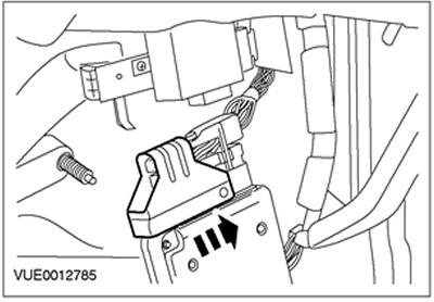
1. Disconnect the ground wire from the battery.
2. Remove the side trim of the instrument panel.
3. Remove the front door trim panel.

Right-hand drive vehicles
4. Remove the lower section of the instrument panel. Disconnect the data link connector.

Left-hand drive vehicles
5. Remove the glove box.

6. Remove the lower section of the instrument panel trim.

7. Disconnect the plug connector of the central security module(CSM).

8. Disconnect the powertrain control module (PCM) mounting bracket.

9. Disconnect the Common Electronic Module (GEM) from the PCM and place it to the side.
10. Disconnect the PCM from the support bracket.

All cars
11. Disconnect the PCM.

12. WARNING: Protect the floor covering before drilling. Failure to follow this instruction may result in damage to the floor covering.
Drill a 3mm diameter pilot hole in the center of the welded nut.

13. Drill an 8mm hole in the welded nut to loosen the shear bolt.
- Remove the shear bolt and discard it as no longer needed.

14. Remove the PCM protective bracket and discard it as no longer needed.

15. Disconnect the PCM connector.
16. Remove the PCM.
Installation
All cars1. Connect the PCM connector.

2. NOTE: Install a new PCM protection bracket.
Install the PCM protection bracket.
3. NOTE: Install a new PCM protection bracket shear bolt.
Install the PCM protection bracket shear bolt.

4. Install the PCM.

Cars manufactured up to 10.2001
5. Attach the PCM mounting bracket.

6. Connect the CSM plug connector.

Cars manufactured since 10.2001
7. Connect the GEM module to the PCM.
Fuel injection system
The fuel injection system consists of three subsystems that, working together, control the combustion process and provide feedback on working efficiency. These subsystems:
1. Air intake
2. Fuel supply
3. Fuel management
The air intake system supplies the air needed for the combustion process and measures the amount of air entering the engine. Typical elements include an air intake, air filter, intake channels, air flow (or mass) meter (or sensor) and others special elements air intake systems.
The fuel supply system supplies gasoline from fuel tank, filters it and supplies it under high pressure to the engine. The system elements include a fuel pump, fuel filter, fuel manifold, fuel injectors, pressure regulator and pulsation damper. On closed-loop engines, the system also includes a fuel line that returns unused fuel to the tank (fuel return line).
The fuel management system has input sensors that take continuous measurements and transmit this information to the engine management computer. The computer determines the amount of fuel to inject and uses output actuators to activate the fuel injectors for a precise period of time. The operation of the engine control computer is discussed in more detail below.
The computer makes several thousand calculations per minute and constantly adjusts the amount of fuel as driving conditions change. These processes occur continuously from the moment the engine starts. Fuel injection is based on an extremely precise measurement of the amount of air injected. Any failure that does not allow this information to be obtained will result in the computer giving an incorrect estimate of the fuel injection parameters.
The computer calculates the amount of fuel to inject based on the input signals it receives about air flow, air mass and intake temperature.
Engine management system
The engine management system is controlled on-board computer, which by various manufacturers called by different names. Below are the two most common names for this computer:
Powertrain Control Module (PCM)
. Engine Control Module (ECM)
In this publication, the engine controller is referred to as PCM.
The PCM is the heart of a modern engine management system. It controls the ignition system, fuel injection system and other elements. PCM is designed to increase engine efficiency and reduce exhaust gas emissions
The PCM maintains a stoichiometric air/fuel ratio when driving at economical speeds. However, driving conditions vary and the stoichiometric air/fuel mixture will not be ideal under all conditions. Depending on the operating conditions, the PCM makes the air-fuel mixture richer or leaner.
The PCM receives information from input sensors and sends control signals to the corresponding output devices, such as fuel injectors. The location of the PCM and sensors depends on the model and manufacturer. Always refer to the Service Station Manual for information on component locations.
PCM input devices
The input sensors continuously supply detailed information related to various aspects of vehicle operation. The following section describes sensors specific to modern systems power unit control.
Ignition pulse signal
The PCM receives the ignition pulse signal from the ignition coil and, based on this signal, sets the amount and timing of fuel injection.
Engine Coolant Temperature Sensor
Richer air-fuel mixtures compensate for poor fuel volatility at low temperatures. The PCM monitors coolant temperature and increases fuel injection volume to improve overall dynamic characteristics car with a cold engine.
The engine coolant temperature (ECT) sensor measures coolant temperature by changes in electrical resistance. The thermistor changes its electrical resistance according to temperature changes.
Intake air temperature sensor
The Intake Air Temperature (IAT) sensor is a thermistor. It is located in the engine air intake system and serves to determine the temperature of the incoming air. The IAT sensor provides a voltage signal that varies with resistance. The sensor resistance and resulting sensor voltage are high when the sensor is cold. As the temperature increases, the resistance and voltage of the sensor decrease.
Crankshaft position sensor (CPS)
The PCM uses engine speed to help set the base injection quantity. The crankshaft position sensor (CPS) can be located on crankshaft or inside the distributor.
A special rotor (impulse wheel), equipped with projections or teeth and located on the crankshaft, rotates rapidly near the sensor. The sensor records the change in magnetic field strength each time a protrusion passes near it.
Engine speed sensor
The engine speed sensor installed in the distributor or the crankshaft angle sensor can be a disk type or a device whose operation is based on the Hall effect.
The disc type sensor uses a slotted disc mounted on a distributor shaft, two LEDs and two photodiodes. One LED indicates the crankshaft angle, while the second LED indicates the cylinder position.
Position sensor camshaft(SMR)
The PCM uses a camshaft position (CMP) sensor to monitor the position of all cylinders and control fuel system and the ignition system. The sensor records the position of the T.M.T. on the compression stroke for cylinder 1 1 and can be located in the distributor or near the camshaft. The CMR sensor detects changes in magnetic field strength caused by protrusions on the camshaft pulley.
Vehicle speed sensor
The Vehicle Speed Sensor (VSS) indicates the speed of the vehicle. There are three common types of VSS sensor - reed relay type and optocoupler type sensors are found in the speedometer, and the electromagnetic type is located secondary shaft gearboxes
Some car manufacturers also use a wheel speed sensor, which is part of the anti-lock braking system brakes
Oxygen sensors
The front oxygen sensor measures the oxygen density in the exhaust gases and sends a corresponding signal to the PCM. The front oxygen sensor is located in front of the catalytic converter. The PCM uses the input signal from the front oxygen sensor to calculate changes in the air/fuel ratio.
In addition, there is a rear oxygen sensor installed behind the catalytic converter. PCM compares signals from two oxygen sensors to monitor efficiency catalytic converter and determining whether the catalytic converter is working properly.
Throttle Position Sensor (TPS)
The throttle position sensor (TPS) is a varistor (potentiometer) mounted on the throttle valve. The throttle body opens and closes via a cable that connects to the accelerator pedal. When the throttle valve is closed, the computer receives a signal low voltage. When the throttle is wide open, the computer picks up a high voltage signal.
Mass air flow/air flow sensor
The mass air flow (MAF) sensor measures the volume and density of incoming air. When making measurements, the MAF sensor is able to take into account the temperature, density and humidity of the air. All these parameters taken together determine the “mass” of incoming air. The computer uses information about the actual mass flow air, which helps calculate the air/fuel ratio.
Other input devices
Depending on the vehicle manufacturer, there are several other input devices available. Other input devices may include the following:
Sensor absolute pressure Manifold AP (MAP) - measures changes in air pressure in the intake manifold.
. Knock sensor - sends a signal to the RCM to reduce the ignition timing in the event of increased detonation.
. Park/Neutral (P/N) Switch - Tells the PCM whether the transmission is in PARK or NEUTRAL or in one of the drive gears.
. Power steering pressure switch (at idle speed) - used to sense high pressure working fluid in the power steering system.
. A/C high pressure switch - sends a “request” to the PCM to turn on the A/C so that the PCM can turn on the A/C compressor.
. Cruise Control Switch - When the PCM receives a cruise control signal, it stores the desired speed in memory to ensure that the speed is maintained.
Output actuators open and close valves, inject fuel, and perform other tasks in response to control signals from the PCM. Some actuators are controlled, while others are simply turned on or off. The length of time during which an actuator operates is its duty cycle. PCM controls work cycles and, depending on need, can either lengthen or shorten them.
Fuel injectors
Fuel is supplied to the engine through fuel injectors. The fuel injectors are controlled by the PCM. Continuous supply of pressurized fuel to the fuel injector is carried out fuel pump. Fuel burner- this is an electromagnetic valve that is activated when the computer provides an electrical circuit to ground, and after that fuel under pressure is “injected” into intake manifold. The computer controls fuel consumption by pulse-width modulation of the time the injector is on. The injector on time is determined by a combination of the previously described PCM input signals.
Idle Air Control Valve
The idle air control (IAC) valve is located in the throttle body. The IAC valve consists of a movable needle that is controlled by a small electric motor called a stepper motor. Stepper motor able to move by performing very precise, measured "steps". The computer uses the IAC valve to control the idle speed of the crankshaft. The IAC valve changes the position of the needle in the idle air passage in the throttle body. Then the pattern of incoming air flow near the throttle valve when it is closed changes.
Electric fuel pump
Most fuel injection systems use an in-tank, relay-controlled electric fuel pump. When the ignition switch is turned on, the computer, by applying battery voltage, energizes a relay that controls the fuel pump. The relay remains on until the engine starts cranking or the engine starts running and the computer receives base pulses. If there are no base pulses, the computer turns off the relay.
Electric cooling fan
Under certain conditions, single or dual electric cooling fans are used to cool the radiator and/or A/C condenser. On most variants, the cooling fans are controlled by the PCM. Computer controlled versions use cooling fan relays. The computer grounds the cooling fan relay to ground, supplying system voltage to the cooling fan motor when some or all of the following conditions are met:
The coolant temperature sensor indicates high temperature coolant
. The A/C system is requested to be turned on. A/C is on, but the vehicle speed is below the set speed
. The pressure on the high pressure side A/C is higher than the set value, the high pressure switch may open
Warning lamp malfunction
The Engine Maintenance Indicator Lamp or Malfunction Indicator Lamp (MIL) illuminates when the ignition switch is turned to the ON position with engine not running. Don't worry about it because it's only quick check lamps. When the engine is running, the MIL is usually not illuminated. If a DTC is stored in memory or the computer enters standby mode, the MIL illuminates, indicating that the computer is grounding the MIL circuit. If the condition changes and the trouble code(s) are no longer present, the light may go out, but the code remains in the computer's memory.
On-board diagnostics
The PCM contains diagnostic software that monitors vehicle operation and records any malfunctions that occur. This software is called on-board diagnostics (OBD).
In 1994, manufacturers began equipping vehicles with PCMs containing the system. on-board diagnostics second generation (OBD II) or EOBD for Europe. Software controls those parameters in fuel injection and emission control systems that can cause an increase in exhaust toxicity. In addition to checking for faulty components, OBD II checks and tests the correct operation of subsystems. In addition, it monitors the deterioration of sensors and actuators.
Fuel pressure regulator control
In some engines, the PCM increases fuel pressure to prevent vapor lock (boiling) when the engine temperature is at relaunch high. For example, if the coolant temperature at startup is 212°F (100°C) or higher, the PCM will activate the pressure regulator control solenoid valve.
When the solenoid valve operates, the vacuum supply to the pressure regulator is reduced, causing fuel pressure to become higher than normal engine operating conditions. Solenoid valve remains activated for a short time after the engine is started.
Basic idle system
The bypass allows some intake air to enter the intake manifold when the engine is idling because the throttle valve is almost completely closed. The IAC valve controls the "bypass" air needed to stabilize the idle speed under various loads (A/C, electrical load, power steering, etc.). IAC valve which is actuator electromagnetic type, RSM is activated. This valve provides precise control of the amount of air that bypasses the throttle valve.
In some vehicles, to control the basic idling a combination of two valves is used: mechanical and electromagnetic. When starting from a cold state, both valves are open, which provides additional air flow during startup and warm-up. As the coolant temperature rises to normal, the mechanical valve gradually closes and air flows only through the solenoid valve.