DYNAMIC ROTOR BALANCING ON A ROTARY MACHINE
Balancing the rotors is a procedure necessary if the rotating part of the machine is out of balance. In this case, the whole machine is shaken (vibrated) during rotation. In turn, this can lead to the destruction of bearings, foundations and, subsequently, the machine itself. To avoid this, all rotating parts must be balanced.
The rotor itself is a rotating part, which is held during rotation by means of bearing surfaces in supports (pins, etc.). The axis of the rotor is a straight line connecting the centers of gravity of the contours on the cross-sections of the center of the bearing surfaces. There are several types of parts:
Two-bearing;
Multi-support;
Inter-support;
Console;
Double-cantilever.
Distinguish between static and dynamic balancing of rotors. The first is performed on prisms, the second when the balanced part rotates.
Specialists of the company "CardanBalance" offer services for high-quality balancing of the rotor. Our centers are equipped with modern equipments that guarantee accurate balancing. This is quite difficult to achieve, because it must completely coincide with the accuracy of manufacturing the rotor. All work is carried out at the stands own development which give balancing accuracy five times higher than the factory requirements!
In this section you can familiarize yourself with the main technical information regarding ways dynamic balancing rotor (method of exceptions, method of B.V. Shitikov). Useful practical material that will provide a basic understanding of the problem. What is hydraulic balancing, what is a wheel balancing machine and other information is clearly stated on our resource. You can also use our services, which include cardan repair, balancing of cargo wheels, crankshaft etc. How much balancing and other works cost is described in the section "Services and prices".
1. INTRODUCTION. BASIC CONCEPTS
When rotating m(mass) around a point (stationary) with w (angular velocity) F (centrifugal force inertia) of this mass:
(1.1)
where and n - normal mass acceleration; Is the distance from the axis of rotation to the center of mass. As the mass moves, F will change direction and exert an effect (vibration) on the supports and through them on the structures attached to the rack.  D(imbalance) -
a vector quantity that is equal to the product of the unbalanced mass and the eccentricity (the radius vector of the center of mass). The value is measured in g / mm.
D(imbalance) -
a vector quantity that is equal to the product of the unbalanced mass and the eccentricity (the radius vector of the center of mass). The value is measured in g / mm.
Moreover, the vectors “ D " and " e " collinear quantities.
In vector form, the formula looks like this:
The vectors F and D are proportional to each other.
2. ROTOR IMBALANCE AND ITS MANIFESTATION
According to GOST 19534-74, a rotor is a body, which during rotation is held in supports by its bearing surfaces. In cars it can be gear, pulley, motor rotor, drum, crankshaft, etc.If the masses are distributed in the rotor so that during rotation they cause loads in the bearings, then it is called unbalanced. Moreover, there are 3 types of rotor imbalance:
- Static. In which the axis of rotation and the main axis of inertia are parallel. In this case, the pressure variables are equal to 0
- Dynamic. In which the main axis and the axis of rotation intersect or intersect, but not at the center of mass, because of this, imbalance occurs most often.
- Instant
In all cases of imbalance of the rotor, the forces of inertia of its masses create dynamic loads. They are eliminated by redistributing the masses (by installing counterweights).
Dynamic balancing is carried out using a special machine equipped with an oscillating frame
3. Balancing the rotor by the way of exceptions
In order to determine the parameters of the mass (correcting) in the plane P, the rotor is installed on the machine and the eccentricity of the mass is assigned. A circle is outlined in the plane, and its center should coincide with the geometric axis of rotation. The radius is taken equal to the selected eccentricity. The circle is divided into 4 parts. We attach the mastic (plasticine) so that the center of the piece coincides with point 1. Let the rotor rotate and measure the vibration amplitude. We write the indicator near point 1.

We transfer the mastic to point 2, accelerate the rotor and again fix its amplitude. We write it down. We fix the other 2 points.
Compare the amplitudes until they turn out to be the smallest. Point K, found by us, defines the final position of the correcting mass. Opposite point H is unbalanced mass.
Now we begin to change the mass of the mastic to the K points and measure the rotor vibrations. This is how we find the value of the correction mass.
4. ROTOR BALANCING BY THE BV METHOD SHITIKOVA
Install the rotor on the frame and accelerate it. After that we fix the amplitude A 1.
We will install additional mass at point P 1 m g with eccentricity e g. At resonance, we fix the amplitude AS.
We rearrange the mass to the opposite point and fix the second amplitude. We designate points on the plane in accordance with the inequality in which the first amplitude is greater than the second.

Using 3 amplitudes, we build a parallelogram and find the fourth amplitude and angle
1Using the formula, we determine the mass proportionality coefficient
m= A g /D g = A g / ( m g e g),Determine the mass imbalance

Now we set the value of the mass (correcting) from the equality of imbalances and find the desired eccentricity
D k = D 1 e k = D 1 / m to.
It remains to determine the points of installation of the weights and test launches to determine the residual amplitude, as well as to assess the quality of balancing in the plane.
D oct = A oct / m
In the company "CardanBalance" you can buy cardan shaft Chevrolet Niva, UAZ driveshaft, Mercedes Vito driveshaft, as well as accessories for other cars. We carry out not only the sale of spare parts, but also their subsequent installation.
For a perfectly balanced electric motor, the axis of inertia of the rotor must coincide with the axis of rotation. But quite often during the operation of the unit, an imbalance occurs, extraneous noise and increased vibration. These signs indicate the need for a motor balancing procedure.
The rotor of the engine is a complex structure consisting of several elements. Each of them is endowed with its own density, probable microdefects and various deviations. All this can cause an imbalance, the value of which can reach critical indicators. Then the balancing of the electric motor becomes the only condition for extending the life of the unit.
The rotor or armature of the motor can be balanced in two ways:
· In dynamic mode;
· In static mode.
The inertial forces arising during the rotation of the rotor and the inertial moments of forces caused by unbalance depend on the angular velocity. Based on this, for electric motors with quiet running, balancing in a static mode is used, and high-speed units are balanced in a dynamic mode.
Static balancing has several disadvantages, including: the duration of the procedure, a large number of measurements and calculations. But the main disadvantage of balancing an electric motor in a static mode is an insufficiently accurate reduction in the unbalance indicator.
But professionals know how to perform balancing with maximum accuracy, therefore, if there is a need for such a procedure, it is recommended to contact experienced specialists in their field.
Our company performs high-quality balancing of all types of electric motors. We provide services by reasonable prices and in the most short time... Call our phone number listed on the website, we will be happy to help you !.


OUR OPPORTUNITIES
Dynamic balancing of vertical and horizontal rotors and shafts
Balancing in own supports at the Customer's enterprise
Balancing on machines
Diagnosing the reasons that impede balancing
Identifying the causes of equipment malfunction
Equipment balancing result
Reduced vibration and increased stress
Increased service life of bearings, couplings and seals
Reducing the likelihood of emergency equipment failure
Reducing electricity consumption
After balancing, all results are recorded in the form of a balancing protocol, reflecting the name of the equipment, accuracy class, geometric parameters, the tolerance band, as well as the initial and final unbalance levels.
Balancing steps
Measurement of initial vibration
Setting a test weight with a known mass
Re-measuring vibration
Calculation of the correction weight and the angle to the installation Installing the weight on the rotor (or metal removal)
New vibration measurement until a result is achieved
Our Balancing Videos:


During operation electric motors rotating parts, in particular the shaft, can get various defects and damage. This may be a defect in the journal of the shaft or its curvature, the shaft may "sink" if the rotor plates are overtightened and some other damage.
After carrying out any repairs on electric cars, v mandatory balancing of the shafts. This procedure can be carried out in a static or dynamic mode. For low-speed machines, static balancing is usually performed, and on units with high rate stroke - dynamic balancing.
For balancing, special machines are used, in which the motor shaft is placed. The work is quite laborious and responsible, therefore, it is unlikely that it will be possible to perform it on your own with high quality. It is better to entrust the implementation of this task to professionals who have sufficient experience and skill in carrying out the procedure.
For static balancing, a special machine with prisms mounted on a support structure is used. The shaft is placed on the working surfaces of the prisms, then the location of the load is determined at one end of the part for balancing. This eliminates static imbalance. After that, the shaft is balanced according to the established rules.
During dynamic balancing, the balance weights are placed on the two ends of the shaft. High-speed shafts have their own runout at each end, which is caused by imbalance. Further, the master performs balancing until the maximum reduction in imbalance indicators.
Our company provides services for balancing the shafts of all types of electric motors. We do our work efficiently, quickly and inexpensively! Call our specialists if you need to perform balancing, they will be happy to answer all your questions!
Balancing ventilation of electric motors
Dynamic balancing of the motor ventilation system is one of the many operations performed to further smooth operation rotating mechanism. Such balancing is carried out either on special balancing machines or on the engine's own mountings.
Why is ventilation balancing done?
All rotating mechanisms are subject to balancing, as well as their elements separately. In case of poor-quality balancing, the engine can begin to vibrate, make noise, lose power, increase energy or fuel consumption. This leads to failure of individual parts of the electric motor or its entirety.
If an asymmetry (displacement of the axis of rotation) or, in other words, an imbalance occurs in a rotating system, troubles immediately arise due to an increase in vibration. The higher the rotation speed, the more pronounced the manifestations of the imbalance become.
The service - "balancing the ventilation system", is provided by our company! Our staff includes only highly qualified specialists who are able to perform this task quickly and efficiently.
If you want to pay as little as possible and pay for the repair of electric motors, then you must follow the operating rules for these devices:
* Balancing the ventilation of the electric motor must be carried out in a timely manner;
* Constantly monitor the health of the equipment;
* The electric motor must be operated with the parameters corresponding to the technical data sheet of the unit;
* Increased vibration phenomena lead to additional loads on the entire engine or its individual parts.
If you need balancing of the ventilation system of the electric motor, then dial the phone number indicated on our website. We will fulfill this work efficiently and on time, and the engine after balancing ventilation will work properly for many years!


Balancing rotating parts
Our organization is engaged in the dynamic balancing of ventilation systems, anchors of electric motors, pulleys, shafts, impellers and other rotating parts both on their supports and on balancing machines.
What is balancing for?
Balancing is a native word for both the car and any other equipment with rotating parts. All rotating parts are subjected to this operation. Flywheel, crankshaft, clutch, propeller shafts, wheels, pulleys, fans, etc. You can't list everything. And it is worth fiddling here, as the imbalance will immediately declare itself with shaking, vibrations, noises exhausting the soul, rapid wear loss of power, increased power consumption or fuel consumption, etc., which leads to premature wear and breakdown of other parts, and in some cases all equipment.
An imbalance occurs when the rotating system is even slightly unbalanced. It is worth slightly shifting the axis of rotation from the center of the part or making this part at least a fraction of a millimeter non-circular (or simply non-uniform in density) - the imbalance with its companions shaking, vibrations and wear is right there. It manifests itself, however, with an increase in the speed of rotation. For example: at a speed of 100 km / h and there is an imbalance of 15-20 g on a 14-inch wheel, the load on the disc will be similar to striking it with a three-kilogram hammer at a frequency of 800 times per minute.
And so the conclusion!
1. If you want to pay less and less often for repairs, follow the rules of operation industrial equipment... Balance on time.
2. The equipment must be in good working order, and the parameters of its operation must correspond technical data sheets... Rotating parts of machines (shafts, pulleys, fans, etc.) must be balanced both as separate parts and as an assembly.
3. Vibration of parts causes additional loads on the part itself and on the parts associated with it.
GOST 12.2.003-91 SSBT. Manufacturing equipment. General requirements security
1.1. Production equipment should ensure the safety of workers during installation (dismantling), commissioning and operation both in the case of autonomous use and as part of technological complexes, subject to the requirements (conditions, rules) provided for by the operational documentation.
Note. Operation includes general case intended use, Maintenance and repair, transportation and storage.
2.1.2. The design of production equipment must exclude, in all envisaged modes of operation, loads on parts and assembly units that can cause destruction, posing a danger to workers.
2.1.11. Design of production equipment driven by electrical energy, should include devices (means) to ensure electrical safety.
2.1.13. Production equipment, which is a source of noise, ultrasound and vibration, must be designed so that noise, ultrasound and vibration in the specified conditions and operating modes do not exceed the permissible levels established by the standards.
Unfortunately, the issues of balancing the crankshaft (flywheel, clutch basket, damper) are practically not disclosed in the available literature, and if anything can be found, then these are GOSTs and scientific literature. However, comprehension and understanding of what is written there requires some preparation and the presence of the balancing machine itself. This, of course, discourages auto mechanics from all the desire to deal with these issues from the point of view internal combustion engine repair... In this short article, we will try to uncover balancing issues from the perspective of an auto mechanic, without going into complex mathematical calculations and focusing more on practical experience.
So the most frequent question arising during engine repair: is it necessary to carry out balancing after grinding the crankshaft?
To do this, we will show all the stages of balancing the crankshaft, which are carried out in our company during the repair of the crankshaft. Take the crankshaft of the MB 603.973 engine as an example. This is an inline 6 cylinder diesel engine... The permissible imbalance of the manufacturer for a given shaft is 100 gmm. Is it a lot or a little? What happens if the imbalance is less or more than this figure? We will not consider these issues in this article, but will describe them later. But we can say with confidence that the manufacturer does not take these figures from the ceiling, but conducts enough experiments in order to find a compromise between acceptable value imbalance for normal operation engine and production costs to ensure this tolerance. Just for comparison, the manufacturer's permissible imbalance per crankshaft is engine ZMZ 406 360 gmm. To make it easier to imagine and understand these numbers, let's recall a simple formula from a physics course. For rotational motion, the inertial force is:
m- unbalanced mass, kg;
r- radius of its rotation, m;
w- angular velocity of rotation, rad / s;
n- rotation frequency, rpm.
So, we substitute the numbers in the formula and take the rotational speed from 1000 to 10,000 rpm, we get the following:
F1000 = 0.1x 0.001x (3.14x1000 / 30) 2 = 1.1 N
F2000 = 0.1x 0.001x (3.14x2000 / 30) 2 = 4.4 N
F3000 = 0.1x 0.001x (3.14x3000 / 30) 2 = 9.9 N
F4000 = 0.1x 0.001x (3.14x4000 / 30) 2 = 17.55 N
F5000 = 0.1x 0.001x (3.14x5000 / 30) 2 = 27.4 N
F6000 = 0.1x 0.001x (3.14x6000 / 30) 2 = 39.5 N
F7000 = 0.1x 0.001x (3.14x7000 / 30) 2 = 53.8 N
F8000 = 0.1x 0.001x (3.14x8000 / 30) 2 = 70.2 N
F9000 = 0.1x 0.001x (3.14x9000 / 30) 2 = 88.9 N
F10000 = 0.1x 0.001x (3.14x10000 / 30) 2 = 109.7 N
Of course, everyone understands that this motor will never reach a speed of 10,000 rpm, but this simple calculation was made in order to "feel" the numbers and understand how important balancing is when the speed increases. What preliminary conclusions can be drawn? Firstly, you "felt" what an imbalance of 100 gmm is, and, secondly, you made sure that this is really a rather tight tolerance for this engine and there is no need to make this tolerance tighter.
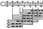
Now let's end the numbers and finally get back to this shaft. This shaft was previously ground and then came to us for balancing. And here are the results we got when measuring the imbalance.

What do these numbers mean? In this figure, we see that the unbalance on the left plane is 378 gmm, and the unbalance on the right plane is 301 gmm. That is, it can be conditionally assumed that the total imbalance on the shaft is 679 gmm, which is almost 7 times higher than the tolerance set by the manufacturer.
Here is a photo of this shaft on the machine:


Now, of course, you will begin to blame the "curved" grinder or a bad machine for everything. But let's get back to simple calculations and try to understand why this is so. For simplicity of calculation, we will take a shaft weight of 20 kg (this weight is very close to the truth for a 6-cylinder crankshaft). The shaft has a residual imbalance, let's say 0 gmm (which is a complete utopia).
And so now the grinder has grinded this shaft to a repair size. But when installing the shaft, he shifted the axis of rotation from the axis of inertia by only 0.01 mm (to make it easier to understand - the grinder did not match the old and new axis rotation by only 0.01 mm), and we immediately got an unbalance of 200 gmm. And if you take into account that the factory shaft always has an imbalance, then the picture will be even worse. Therefore, the figures that we received are not out of the ordinary, but are the norm after grinding the shaft.
And if we consider that the manufacturer does not always maintain its own tolerances, then the accusations against the grinder or the machine simply disappear. Just do not now stand over the grinder and demand that he expose the shaft with micron precision, all the same it will not bring the desired result. The only correct way out of this situation is the obligatory balancing of the crankshaft after grinding it. Traditionally, the balancing of the crankshaft is performed by drilling the counterweight (sometimes it is true that you have to make the counterweights heavier, but this is a fairly rare case).


Residual unbalance on the left plane is 7 gmm and 4 gmm on the right plane. That is, the total imbalance on the shaft is 11 gmm. Such accuracy was made on purpose to show the capabilities of this machine and, as you now understand, there is no need to fulfill such requirements when balancing after grinding the shaft. The manufacturer's requirements are sufficient. So, we are finished with the shaft, and, naturally, the question arises, is it necessary to balance the front damper (pulley), flywheel, clutch basket. Let's turn to the repair literature again. What does the same ZMZ recommend, for example, for the permissible imbalance of these parts? On the front pulley with a damper 100 gmm, on the flywheel 150 gmm, on the clutch basket 100 gmm. But there is a very important note.
All these parts are balanced separately from the shaft (that is, on mandrels), and the crankshaft assembly is not balanced in series at modern engine factories. That is, you understand that when the above parts are installed on the crankshaft, the residual unbalance will naturally change, since the coincidence of the axes of rotation is almost impossible. Below are photos of balancing these parts.


Again, as practice has shown, these parts make a significant contribution to the imbalance of the crankshaft, and, as our experience has shown, the imbalance of each of these parts significantly overlaps the residual imbalance tolerances. So, the figure 150-300 gmm is the "norm" for the front pulley (damper), for the flywheel 200-500 gmm, and 200-700 gmm for the clutch basket. And this applies not only to Russian car industry... As our experience has shown, approximately the same figures are obtained from the foreign car industry.
And there is definitely another very important point: after balancing the parts separately, balancing must be done as an assembly, but it must be done on the last stage... Individual pre-balancing is also mandatory. This is so that if the flywheel or clutch fails, you do not have to remove the knee to rebalance again.


So, this is what we get finally when balancing the assembly.

The final unbalance of the crankshaft assembly is 37 gmm.
It should be borne in mind that the weight of the shaft assembly was about 43 kg.
But, having completed the balancing of the crankshaft assembly, do not forget about the weight distribution of the pistons and connecting rods. Moreover, the weight distribution of the connecting rods must be done not just by weight, but by the weight distribution by the center of mass, since the difference in the weight of these parts also contributes to the engine imbalance and is strictly regulated by the manufacturer.
And here's what I would like to note in conclusion: many auto mechanics, after reading this article, will say that this is all nonsense. That they have collected more than a dozen motors, and that they all work fine without balancing, and they will be right - they really work. But let's remember how many engines we had to see that worked…. with broken guides, with worn out camshaft cams, with milled on cylinder head plane 2-3 times higher than the norm, with worn out cylinders 0.3 mm, with incorrectly installed pistons - the list goes on and on.
Everyone, probably, has a couple of their examples, when the engine worked contrary to all laws. Why honing cylinders, because before they only sharpened and everything worked? or: Why use hon-bars when you can apply a mesh with a regular sandpaper? Why "catch" these hundred square meters, because it already works? So why, following one of the manufacturer's requirements, others are neglected? Just do not think that by balancing the crankshaft assembly and weighing the pistons and connecting rods, you will get a "miracle" that your standard engine from VAZ will become, according to its characteristics, like a motor from a Formula 1 car. This will not happen to you. ... After all, balancing is one of the building blocks, which, together with the fulfillment of other repair requirements, gives you confidence that the engine you repaired will work out at least the resource of the new engine. And the more minders follow the requirements of car manufacturers when repairing an engine, the fewer motorists there will be who believe that the engine after overhaul more than 50-70 thousand km does not work.
About the service
High-quality professional repair and balancing of the cardan shaft in Moscow and the Moscow region is carried out by the company "KARDAN-GARANT" on the latest certified equipment of European quality. Cardan balancing in Moscow and the Moscow region is one of the most demanded operations to identify and eliminate vibration in cars. Balancing is important and necessary after carrying out any operations with the propeller shaft. Cutting, lengthening and shortening, replacing flanges and forks of the propeller shaft of passenger and freight transport, replacement of CV joints and crosspieces, replacement of suspension supports, spline joints, restoration mounting holes under crosses, metal spraying and much more. And it is important to balance the cardan on certified equipment in a specialized technical center, which is obliged to give an absolute result and provide a guarantee for all types of work. Our balancing equipment allows for dynamic balancing of a cardan shaft with a length of more than 4500 mm and a speed of more than 5000. We can provide this service for cars, commercial vehicles, trucks and special equipment. We also balance industrial shafts from the light and textile industries, our customers are from coffee companies, where balancing of the crushing shafts for beans is necessary. In the textile industry, these are special rollers for applying patterns on fabrics, there must be a perfectly flat surface. Still similar industrial shafts are used in the printing industry. We carefully monitor our equipment, we carry out mandatory preventive maintenance. We are trying to achieve maximum quality at work. We will be glad to see you visiting us!
| Domestic passenger car 2-support card. | RUB 2,000 | ||
| Domestic passenger car 3-support card. | RUB 2,500 | ||
| Domestic passenger car 4-support card. | RUB 3,000 | ||
| Foreign car car 2x-support card. | RUB 2,000 | ||
| Foreign car car 3-support card. Shaft | RUB 2,500 | ||
| Foreign car car 4-bearing card. | RUB 3,000 | ||
| MB Sprinter, VW Crafter 3-bearing card. | RUB 2,500 | ||
| MB Sprinter, VW Crafter 4-bearing card. | RUB 3,000 | ||
| Ford Transit 3-bearing card. Shaft | RUB 2,500 | ||
| Ford Transit 4-bearing card. | RUB 3,000 | ||
| Repair, balancing, installation | |||
|---|---|---|---|
| Removing the propeller shaft | from 500 rubles | ||
| Installing the propeller shaft | from 500 rubles | ||
| Replacing the crosses | 600 - 900 rubles. | ||
| Replacing the propeller shaft suspension supports | from 700 rubles | ||
| Replacement spline connection | RUB 2500 | ||
| Editing the propeller shaft tube | from 1500 rub. | ||
| Shortening the propeller shaft tube | RUB 2500 | ||
| Extension of the propeller shaft tube | RUB 5,000 | ||
| Geometry restoration seat flange and forks |
RUB 1,500 | ||
In "KARDAN-GARANT" we are ready to carry out accurate balancing of the cardan shaft for domestic and foreign cars, cars and trucks, including special equipment.
When carrying out these measures, it is necessary to take into account the fact that the cardan transmission consists of two or more rotating elements and represents a single system that needs to be balanced as a whole assembled, as it is installed in a particular car.
Repair and balancing of cardan shafts is carried out on modern equipment having the necessary certificates. With the help of such tools, the company can mount cardan transmission weighing up to three hundred and fifty kilograms, which consist of two or more rotating elements. The equipment can be used to balance the gimbals of trucks, limousines and minibuses. In this case, the value of shaft revolutions can reach five thousand per minute.
If you do not make a timely adjustment of the cardan, then its vibration will increase the load on the critical components of the machine (gearbox, gearbox, bridge). In addition to discomfort when driving, this can lead to failure of the cardan joints, and this will already mean more expensive repairs.
Propeller shaft imbalance: causes and troubleshooting techniques
Balancing of cardan shafts in Moscow should be carried out in the following cases:
- at a speed of seventy kilometers per hour and above, the vibration of the car begins;
- during acceleration and during braking, a characteristic knock is heard from the side of the cardan;
- after renovation works connected with the cardan, including after installation and dismantling;
- after changing the crosspieces and the constant velocity joint.
The price of balancing the cardan depends on the complexity of the work and on the brand of the car. Among the main reasons for the problem of cardan imbalance, the following should be noted:
- operational wear of components (crosses, suspension pores, spline joints);
- use in the repair of defective and low-quality parts;
- loss of balancing weights during vehicle operation;
- abrupt starts and stops vehicle;
- untimely maintenance of crosspieces and cardan joints;
- overloading of a vehicle
- deformation of a rotating element as a result of external influences.
Cardan repair and balancing measures should be carried out in special workshops or technical centers, where there is the necessary professional equipment. Repair work takes no more than 2 hours, provided that they are carried out by a qualified specialist with extensive experience.
If an imbalance is detected, first of all, they carry out diagnostics and determine exact reason Problems. The matter may be in improper docking after independent intervention in the operation of the universal joint, corrosion, detachment of the balancing plate, deformation of the pipe, backlash in the crosspiece, etc.
Only high-precision balancing of the gimbal or why us?
The company "CARDAN-GARANT" offers to carry out high-precision balancing of the cardan in operational terms. Low price balancing the propeller shaft is not our only advantage. Among other advantages, professional craftsmen should be noted. high level, innovative equipment and efficiency of execution.
Call us, leave applications, we will answer any questions arising on the repair.
We will consult you completely free of charge and give you the best answer.
We look forward to seeing you!
Always with you, CARDAN-GARANT.
The balancing of the propeller shaft can be done both with your own hands and at a service station. In the first case, this requires the use of special tools and materials - weights and clamps. However, it is better to entrust the balancing to the workers of the workshop, since it is impossible to calculate the weight of the balancer and its installation location with accuracy manually. There are several "popular" balancing methods, which we will discuss below.
Signs and causes of imbalance
The main symptom of an imbalance in the propeller shaft of a car is vibration the entire machine body. At the same time, it increases as the speed of movement increases, and, depending on the degree of imbalance, it can manifest itself both at a speed of 60-70 km / h, and more than 100 kilometers per hour. This is due to the fact that when the shaft rotates, its center of gravity shifts, and the resulting centrifugal force, as it were, "throws" the car on the road. An additional feature in addition to vibration is the appearance characteristic hum coming from under the bottom of the car.
Imbalance is very harmful to the transmission and chassis of the vehicle. Therefore, when its slightest signs appear, it is necessary to balance the "cardan" on the machine.

Neglect of breakage can lead to such consequences.
There are several reasons for this breakdown. Among them:
- natural wear and tear parts during long-term operation;
- mechanical deformation caused by impacts or excessive loads;
- manufacturing defects;
- large gaps between the individual elements of the shaft (if it is not one-piece).
The vibration felt in the passenger compartment may not come from the propeller shaft, but from unbalanced wheels.
Regardless of the reason, when the symptoms described above appear, an imbalance check must be performed. Repairs can also be carried out in your own garage.
How to balance the gimbal at home
Let's describe the process of balancing the driveshaft with our own hands using the well-known "old-fashioned" method. It is not difficult, but it can take quite a while to complete. a lot of time... You will definitely need observation pit, on which you must first drive the car. You will also need several weights of different weights to use when balancing the wheels. Alternatively, instead of weights, you can use chopped welding electrodes.

A primitive weight for balancing the gimbal at home
The work algorithm will be as follows:
- The length of the propeller shaft is conventionally divided into 4 equal parts in the transverse plane (there may be more parts, it all depends on the amplitude of vibrations and the desire of the car owner to spend a lot of time and effort on this).
- The above-mentioned weight is securely attached to the surface of the first part of the propeller shaft, but with the possibility of further dismantling. To do this, you can use a metal clamp, plastic tie, tape or other similar device. Instead of a weight, you can use electrodes, of which several pieces can be put under the clamp at once. As the mass decreases, their number is reduced (or vice versa, with an increase, they are added).
- Further testing is carried out. To do this, they drive a car onto a flat road and analyze whether the vibration has decreased.
- If nothing has changed, it is necessary to return to the garage and outweigh the load to the next piece of the propeller shaft. Then repeat testing.

Installation of a weight on a cardan
Items 2, 3 and 4 from the above list must be followed until you find on cardan shaft the area where the weight reduces vibration. Further, in the same way experimentally, it is necessary to determine the mass of the weight. Ideally, with the right selection vibration should disappear at all.
The final balancing of the "gimbal" with your own hands consists in rigid fixation of the selected weight. For this, it is advisable to use electric welding. If you do not have it, then in last resort you can use a popular tool called "cold welding", or tighten it well with a metal clamp (such as a plumbing clamp).

Balancing the propeller shaft at home
There is another one, albeit less effective method diagnostics. In accordance with it, it is necessary dismantle the propeller shaft from the car. After that, you need to find or pick up a flat surface (preferably perfectly horizontal). Two steel corners or channels are placed on it (their size is not important) at a distance slightly less than the length of the propeller shaft.
After that, the cardan itself is placed on them. If it is bent or deformed, then its center of gravity is shifted. Accordingly, in this case, it will scroll and become in such a way that its heavier part is at the bottom. This will be a clear indication to the car owner in which plane it is necessary to look for an imbalance. Further actions are similar to the previous method. That is, weights are attached to the propeller shaft and their attachment points and mass are experimentally calculated. Naturally, the weights are attached on opposite side from the one where the center of gravity of the shaft is displaced.
Another effective method is to use a frequency analyzer. You can do it yourself. However, a program is needed that simulates an electronic oscilloscope on a PC, showing the level of the frequency of the oscillations that arise when the cardan is rotating. You can say it from the Internet in the public domain.
So, to measure sound vibrations, you need a sensitive microphone in mechanical protection(foam rubber). If it is not there, then you can make a device from a speaker of average diameter and a metal rod, which will transmit sound vibrations (waves) to it. To do this, a nut is welded into the center of the speaker, into which a metal rod is inserted. A wire with a plug is soldered to the speaker outputs, which is connected to the microphone input in the PC.
- The drive axle of the car is hung out, allowing the wheels to rotate freely.
- The driver of the car "accelerates" it to the speed at which vibration usually occurs (usually 60 ... 80 km / h, and gives a signal to the person who takes the measurements.
- If you are using a sensitive microphone, bring it close enough to the marking site. If you have a speaker with a metal probe, then it must first be fixed to a place as close as possible to the applied marks. The result is recorded.
- On the driveshaft, conditional four marks are applied around the circumference, every 90 degrees, and they are numbered.
- A test weight (weighing 10 ... 30 grams) is attached to one of the marks using a tape or a clamp. You can also use the clamp bolt directly as a weight.
- Next, measurements are taken with a weight at each of the four places in sequence with numbering. That is, four measurements with the movement of the load. The results of the vibration amplitude are recorded on paper or computer.

The location of the imbalance
The result of the experiments will be the numerical values of the voltage on the oscilloscope, which differ from each other in magnitude. Next, you need to build a circuit on a conditional scale that would correspond to the numerical values. A circle is drawn with four directions corresponding to the location of the load. From the center along these axes on a conventional scale, segments are plotted according to the received data. Then you should graphically divide in half segments 1-3 and 2-4 by segments perpendicular to them. A ray is drawn from the middle of the circle through the point of intersection of the last segments until it intersects with the circle. This will be the point where the unbalance is located, which must be compensated for (see figure).
The desired point for the location of the compensation weight will be at the diametrically opposite end. As for the weight of the weight, it is calculated by the formula:
- imbalance mass - the desired value of the mass of the imbalance to be set;
- vibration level without test weight - voltage value according to the oscilloscope, measured before installing the test weight on the gimbal;
- the average value of the vibration level is the arithmetic average between the four voltage measurements on the oscilloscope when the test weight is installed at the four indicated points on the gimbal;
- the value of the mass of the test load - the value of the mass of the established experimental load, in grams;
- 1.1 is a correction factor.
Usually the mass of the imbalance to be set is 10 ... 30 grams. If for some reason you did not succeed in accurately calculating the mass of the unbalance, you can establish it experimentally. The main thing is to know the installation location, and to correct the mass value while driving.
However, as practice shows, self-balancing of the driveshaft using the method described above only partially eliminates the problem. The car can still be driven for a long time without significant vibrations. But it will not be possible to get rid of it completely. Therefore, other parts of the transmission and chassis will work with it. And this negatively affects their performance and resource. Therefore, even after self-balancing, you need to contact a service station with this problem.
Technological repair method

Cardan balancing machine
But if for such a case it is not a pity for 5 thousand rubles, this will be the price of balancing the shaft in the workshop, then we recommend that you go to the specialists. Carrying out diagnostics in repair shops involves the use of a special stand for dynamic balancing. For this, the propeller shaft is removed from the machine and installed on it. The device includes several sensors and so-called control surfaces. If the shaft is unbalanced, then during rotation it will touch the mentioned elements with its surface. This is how geometry and its curvature are analyzed. All information is displayed on the monitor.
Repair work can be carried out using various methods:
- Installation of balance plates directly on the surface of the propeller shaft. Moreover, their mass and installation location are accurately calculated computer program... And they are attached using factory welding.
- Balancing the propeller shaft on a lathe. This method is used in case of significant damage to the geometry of the element. Indeed, in this case, it is often necessary to remove a certain layer of metal, which inevitably leads to a decrease in the strength of the shaft and an increase in the load on it in normal operation modes.
You cannot make a similar machine for balancing cardan shafts with your own hands, since it is very complicated. However, without its use, high-quality and reliable balancing will not be possible.
Outcomes
It is quite possible to balance the gimbal yourself at home. However, it must be understood that it is impossible to independently select the ideal mass of the counterweight and the place of its installation. That's why DIY repair possible only in the case of minor vibrations or as a temporary method of getting rid of them. Ideally, you need to go to a service station, where you will balance the gimbal on a special machine.