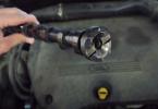
Toyota 1AZ-Fe / FSE 2.0 l engine.
Engine Characteristics Toyota 1AZ
| Production | Kamigo Plant. Shimoyama Plant. |
| Engine brand | 1AZ. |
| Years of release | 2000 |
| Cylinder block material | aluminum |
| Supply system | injector |
| A type | in line |
| Number of cylinders | 4 |
| Valves on cylinder | 4 |
| Piston stroke, mm | 86 |
| Cylinder diameter, mm | 86 |
| Compression ratio | 9.6 9.8 10.5 11 |
| Engine volume, ccmm | 1998 |
| Engine Power, L.S. / Ob. Min | 145/6000
150/5700 150/6000 152/6000 |
| Torque, Nm / Ob.min | 190/4000
193/4000 193/4000 200/4000 |
| Fuel | 95 |
| Environmental norms | Euro 5. |
| Engine weight, kg | 131 |
| Fuel consumption, l / 100 km (for RAV4 XA20) - city - Rouss - Mixed. |
11.4 7.3 9.8 |
| Oil consumption, gr. / 1000 km | up to 1000. |
| Engine oil | 0W-20 5W-20 |
| How much engine oil | 4.2 |
| Replacing the oil is carried out, km | 10000
(better than 5000) |
| Engine operating temperature, hail. | - |
| Engine resource, thousand km - According to the plant - on practice |
N.D. 300+ |
| Tuning - Potential - without loss of resource |
200+ n.D. |
| The engine was installed | Toyota Avensis Verso. Toyota Noah / Voxy Toyota Gaia Toyota isis Toyota Wish Toyota Allion. Toyota Opa. |
Multiplers and repair engine 1AZ-FE / FSE
A series of Toyota engines, a series of engines, a popular and well-proven, family of motors, replaced the AZ series. In the new engines, the cylinder block has become light aluminum, the VVTI timing phase change system is used on the intake shaft, the direct fuel injection (FSE modification) is used, to reduce loads on the sleeve, the cylinder axis is shifted relative to the crankshaft axis, an electronic throttle valve and so on is applied. Directly, the 1AZ-Fe / FSE engine is a replacement for all known, but unlike the predecessor, on the new engine, the release of modifications has not reached such a sweep ...
Motor modifications Toyota 1AZ
1. 1AZ-FE is a basic motor motor, compression ratio 9.6 and 9.8. Power 145 and 150 hp The engine is produced from 2000 to the present.
2. 1AZ-FSE (D4) is an analogue of 1AZ-FE, but with direct fuel injection. Degree of compression, depending on the modification, 9.8, 10.5 and 11. Engine power, respectively, from 150 to 155 hp
Malfunctions, problems 1AZ and their causes
1. Cutting the thread in a block for fastening the GBC. The main problem of all AZ engines, symptoms: antifreeze on the rear wall of the cylinder block, overheating, loss of geometry, block on the garbage ... is solved by the restoration of the thread, or the replacement of the cylinder block to the updated 2007 issue and younger, it was then that the problem was eliminated.
2. Engine vibration at idle. It is manifested, as a rule, with a drop of revolutions to 500-600 rpm and does not give a quiet life to the owners. This feature of the motor with which it is useless to fight, you can clean the idling valve, throttle, nozzles, EGR system (if any), DMRV, check the pillows, in the end, it will partially help.
3
. Twisted 1AZ engine.Clean the throttle valve unit and the hug in the intake manifold with its dampers, the motor is subject to nagar formation, it will help. If the malfunction remained, see Vvti and lambda probe.
In addition, on models for the Japanese market equipped with an EGR system, there is a traditional problem with the formation of a car and the subsequent swimming of turnover, power loss and total stupidity of the car. The problem is solved by cleaning or plug a miracle of the valve. Overheating of the 1AZ engine is fraught with the loss of geometry and the replacement of the motor to the contract. FSE versions (D4) are very sensitive to fuel, fueling the motor slag, there is a chance to get on the replacement of the pump and the nozzles, the cost is quite high. The timing chain is normal, on average more than 200 thousand km walks, does not replace and the replacement does not ask. Despite the block disposable, the engine resource is high, the mileage for 300 thousand km is not at all uncommon. In general, the engine is good, if you follow the condition and pour good oil, then 1AZ will not let you down.
On the basis of this engine, there was a conclusive fellow, 2.4 liter 2AZ, a separate one. In 2007, a new ZR series of Toyota motors was presented and the model began to gradually displace 1AZ.
Toyota 1AZ-Fe / FSE Engine Tuning
Chip tuning. Atmo
There are options for the alteration of the engine in 2.4 liter 2AZ, but the cost of such things is far from reasonable. Therefore, we consider the most relevant option to increase the capacity - reducing.
Compressor on 1AZ-FE / FSE
On AZ engines, Blitz and TRD companies, ready-made whales compressor, you only need to buy, install, supplement it in the intercooler, bloutoff, thick gasket of CHC, 440SS injective nozzles, Walbro 255 LPH pump, remove the catalyst, or replace the exhaust on the forwarding diameter 63 mm, set up on Greddy E-Manage Ultimate and get your 200 hp On standard piston. You can leave the brain to leave the standard, but it will be unambiguously worse.
Sergey -- 2005-09-30 04:41:24
In June 2005, I bought Toyota Nadia Type Su s 2001 in the commoner "Drying" with the engine 1 AZ-FSE (D-4) 152 hp Body brand Ta- ASN10H-AHSSH. Bought on the market of Krasnoyarsk cars without a run in Russia on the speedometer was 64,000 km. The car was in perfect condition, immediately visible on the bottom went not to its move.
As it should be supposed immediately flooded the oil Mobil 1 and changed the filter. Filled exclusively with gasoline AI-92. At first everything was fine. Traveled yes I was glad. But the joy was short-lived - only 3 months. Now mileage on speedometer 71868.
After 2 months, the machine began occasionally twisted while driving. Further - more, as the disease says progressed. He sinned on the candle, changed but did not receive the effect. Soon, with a sharp press on the pedal, the car began to shy, as if someone had held it from behind. Disappeared. Slowly began to approach treason. And then on the forum it was read about the D-4 and the prices of the TNVD and in general I was flooded. I decided to quickly change the fuel filter and buy a praised additive to the Castrol TBE fuel, but did not have time.
A couple of days ago, I went from the morning to work, as usually started the car warmed, I went, the car began to pull the stronger the former, but I didn't want to go to the ride at all, it was also manifested for a rumor some other stranger. As a result, the car stalled. For a while, I still rolled out the quick-end car (because on the forum they wrote that cars live 6-12 months, and then there are only 3 - just a record!). On the instrument panel, the oil icon caught fire and in the top row to the right in front of the ABS light bulb icon something like "engine", I do not know exactly what it means.
I tried to start, started not immediately, an extraneous sound - the type of metallic stripping was present. The car worked extremely not stable, and when pressed on the pedal immediately, Glohla. Something like drove to home. Well, I think and came "Pizdets" $ 20000, as the happiness said was huge, but not long.
And then the fuel filter was brought from the city - the original and additive of yours. Replaced the filter - the effect of zero. Since six drops of oil with a probe in the water - 3 times it broke up with a rainbow film, and 3 times remained in the form of an oil drop, so do the output falls in oil into the oil or not. The oil level is normal, no more and no less. Gasoline oil does not smell. But in all the signs read by me on the forum, the diagnosis of one - covered with a copper pelvis of the TNVD or an electric valve.
Well, now I have to everyone who hears a series of questions. Whether you faced the repair with 1AZ-FSE engines (D-4) 152 hp V \u003d 2 liters? How to check the working pump or not? How to check the electroclap? Is the TNVD and an electric valve with a 3S-FSE engine or from which other? Is it possible to repair my TNLD and how? If not, then where to buy it is cheaper, because prices will jump from 195 green to $ 850, depending on the region. As the money says not too much.
The question is just right for our FAQ on the topic "Is it worth buying D-4". Even with a successful outcome, in which, however, there is no doubt.
The existential offers such a TNVD for ... $ 1164.57. That is, not quite such, and the updated version of 2003. But the order of numbers inspires respect (and this is one of the cheapest stores on the expanses of Russia). From the 3S-FSE pump is not suitable. But the European 1AZ-FSE pump for $ 622. Who scolded there "levory" garbage ":)?
About the film on the water is rather myth. First, it is necessary to compare two drops of the same oil from the crankcase and from the filler bank - it is blown and how much, it depends on the type-grade-grade of a particular fluid. Secondly, in the oil of any engine, one way or another is some gasoline, seeping into the carcase at a start-up, warming on the enriched mixture, interruptions and PCH, and then gradually evaporating ...
About the filter with a sump from diesel - myth. It is enough to imagine the difference between the driving pump of the diesel pump and the pumping electric pump in the tank. And compare the pressure develops and costs.
Adapted pumps - myth. Adapt (in terms of fighting eco-fading) catalysts and the work algorithms of the ECU. EURO-1AZ-FSE pumps really show themselves not bad - but, first, they are still _Name_ (and not with an unknown twisted mileage and dark history). And secondly, in D-4 there is something to immobilize the car and without the participation of the fuel pump.
Direct Toyota Injection System D-4
11.02.2009
Diagnostics and repair of injection and ignition systems 3S-FSE, 1AZ-FSE, 1JZ-FSE Toyota D-4
The direct injection system on Toyota (D-4) was announced in early 1996, in response to GDI from competitors. In the series, such an engine (3S-FSE) has been launched from 1997 to the Corona model (Premio T210), in 1998 - began to be installed on the Vista and Vista Ardeo model (V50). In more than the immediate injection appeared on the row sixteen 1JZ-FSE (2.5) and 2JZ-FSE (3.0), and since 2000, after replacing the S series on the AZ series, the D-4 1AZ-FSE engine was launched.
I had to see the first 3S-FSE engine at the beginning of 2001. It was Toyota Vista. I changed the oil-changing caps and simply studied the new engine design. The first information about him appeared later in 2003 at the Sakhalin site from Kutan Vladimir Petrovich. The first successful repairs gave an indispensable experience to work with this type of engines, which will not surprise anyone now. Then, I looked weakly, with which miracle is dealing with. The engine was so revolutionary that many repairmen simply refused repairs. Applying an edge, high pressure, two catalysts, an electronic throttle, stepper Motor control EGR, tracking the position of additional dampers in the intake manifold, VVTI system, and an individual ignition system The developers have shown that a new era of economical and environmentally friendly engines has come.
Photos are shown a general view of the 3S-FSE engines, 1AZ-FSE, 1JZ-FSE.


A direct injection engine block diagram on an example 1AZ-FSE is as follows.

It should be noted the following important systems and their elements that most often have defects.
Fuel supply system: submersible electric pump in a tank with a fuel mesh and an outlet fuel filter, a high-pressure fuel pump mounted on a cylinder head with a camshaft drive, a fuel ramp with a reduction valve.
Synchronization system: crankshaft and camshaft sensors. Control system:
Sensors: Mass flow of air, coolant temperature and encompaired air, detonation, gas pedal positions and throttle, pressure in the intake manifold, fuel pressure in the ramp heated oxygen sensors;
Executive devices: ignition coils, nozzle control unit and nozzle themselves, pressure adjustment valve in ramp, vacuum solenoid control of dampers in the intake manifold, Coupling valve VVT-I. This is not the entire list, but this article does not pretend to be a full description of direct injection motors. The above scheme, naturally, corresponds to the structure of the fault codes and current data. If there are codes in memory, you need to start with them. Moreover, if there are many of them, analyze them meaninglessly, you need to rewrite, erase and send the owner to a trial trip. If the test lamp lights up, read again and analyze the narrower list. If not - immediately go to the analysis of current data.
When diagnosing the engine, the scanner issues the date of order (80) of the parameters to estimate the state and analyzing the operation of the sensors and the engine systems. It should be noted that a large drawback of 3S-FSE is the absence in the date of the parameter - "fuel pressure". But, despite this, the date is very informative and, with the right understanding, it definitely reflects the operation of the sensors and systems of the engine and automatic transmission.
For example, let's see for one correct date and several dates fragments problems with a motor3S-FSE.
On this fragment, the dates see normal injection time, ignition angle, discharge, engine speed at idle, engine temperature, air temperature. The position of the throttle and the sign of the presence of idling.
In the following picture, you can estimate the fuel correction, the testimony of the oxygen sensor, vehicle speed, the position of the EGR motor.
Then turn on the air conditioner coupling, the valve of the fuel vapor capture, VVTI valve, Overdrive, solenoids in the automatic transmission
As you can see by the date you can easily rate the work and check the functioning of almost all major sensors and engine systems and automatic transmission. If you build a number of readings, you can quickly assess the engine status and solve the problem of incorrect operation.
The following fragment shows an enlarged fuel injection time. Date received by a DCN-Pro scanner.

And on the following fragment, the incoming air temperature sensor (-40 degrees), and a long-term injection time (1,4ms with a 0.5-0.6 ms standard) on a heated motor.

Abnormal correction makes the first debt, the presence of gasoline in oil.
Control unit accepted mixture (-80%)

The most important parameters that are fully displayed by the engine status are lines with long and short fuel correction testimony; Oxygen sensor voltage; Purgeration in the intake manifold; Engine rotation speed (revs); EGR motor position; the position of the throttle percentage; ignition advance angle and fuel injection time. For a faster valuation of the engine mode, the line with these parameters can be built on the scanner display. Below on the photo example of a fragment of the engine operation date as usual. In this mode, the oxygen sensor switches, the recovery in the collector 30 kPa, the throttle is open by 13%; The advance angle of 15 degrees. EGR valve closed. Such a layout and selection of parameters will save time on checking the engine status.
Here are the basic lines with the parameters for engine analysis.


And here is the date in the door of the door. When switching to the depleted operation, the throttle is open, EGR opens, the oxygen sensor voltage is about 0, 60 kPa vacuum, 23 degrees ahead. Such is the mode of operation in the depleted mode.
To compare a fragment of the dates of the depleted mode with a DCN-Pro scanner

It is important to understand that if the engine works correctly, then subject to certain conditions, it should go to the depleted mode of operation. The transition occurs when the engine is exceeding and only after the relegation. Many factors define the engine transition process into the depleted mode. When diagnosing the fuel pressure, and the pressure in the cylinders, and the intake manifold pressure, and the proper operation of the ignition system should be taken into account.
Now let's see the date from the engine 1AZ-FSE. The developers corrected missed errors, there is a lifting with pressure. Now it is possible to evaluate the pressure in various modes without hassle.
The next photo is visible in the usual mode of fuel pressure 120kg.

In the depleted mode, the pressure is reduced to 80 kg. And 25 degrees are set to 25 degrees.

The date from the 1JZ-FSE engine is practically no different from the date of 1AZ-FSE. The presence of the work is only that when decorating the pressure is lowered to 60-80 kg. As usual 80-120kg. With the full date, which gives the scanner, in my opinion, does not reach one very important parameter to estimate the durability of the pump. This is the parameter of the pressure regulator valve. In the duty of control pulses, you can evaluate the "power" of the pump. Such a parameter is in the date of Nissan. The dates from the VQ25 DD motor are shown.
Here it is clearly visible as pressure adjustment when changing control pulses on the pressure regulator.
 |  |
The following photo presents a dates (basic parameters) of the 1JZ-FSE engine in the depleted mode.

It should be noted that the 1JZ-FSE engine is able to work without high pressure (as opposed to 4-cylinder fellow), the car is capable of moving. However, if any serious, and not very serious interference (malfunctions) of the transition to the depleted regime will not happen. Dirty damper, problems in sparking, fuel feed, gas distribution do not allow moving. In this case, the pressure block lowers up to 60 kg.
On this fragment, you can see the absence of a transition and a one-stop damper, which indicates the contamination of the channel X / x. The depleted regime will not be. And to compare the date fragment in the usual mode.
 |  |
Constructive execution.
Fuel rail, nozzles, tnvd.
On the first engine with HB designers applied collapsible injectors. The fuel rail has a 2-storey design of different diameters. It is necessary for pressure leveling. In the following photo, high pressure fuel elements of the engine 3S-FSE.
Fuel rail, fuel pressure sensor on it, pressure emergency discharge valve, injectors, fuel pump High pressure and main tubes.

Here is a 1AZ-FSE fuel rail rail, it has a simpler design with one passing hole.

And the next photo shows the fuel rail from the engine 1JZ-FSE. The sensor and valve are located nearby, the injectors differ from 1AZ-FSE only with color winding and performance.

In engines with NV, the work of the first pump is not limited to 3.0 kilograms. Here the pressure is somewhat higher than about 4.0 - 4.5kg to ensure complete power supply of the pump in all modes of operation. Measurement of pressure during diagnostics can be made to a manometer through the input port directly on the pump.
When the engine is started, the pressure should be "crawling" to his peak in 2-3 seconds, otherwise the launch will be long or not at all. Below in the photo Measurement pressure on the engine 1AZ-FSE

The following photo froze the first pump pressure on the 3S-FSE engine (pressure below the norm, the first pump must be replaced.)

Since the engines were produced for the domestic market in Japan, the degree of fuel purification is not different from ordinary engines. First grid grid before pump.

For comparison, the dirty and new grid of the first engine of the 1AZ-FSE engine. In such contaminants, the grid must be changed or cleaned by carbcliner. Gasoline sediments are very tightly pack, the pressure of the first pump decreases.

Then the second shaft-cleaning filter engine (3S-FSE) (by the way, it does not delay the water).
When replacing the filter, the incorrect assembly of the fuel cassette is incorrect. In this case, there is a pressure loss and not launch.


This is what the fuel filter looks like after 15 thousand runs. Very decent barn of gasoline garbage. With a dirty filter, the transition to the depleted mode is either very long, or it is not at all.

And the last flap to filter the fuel mesh at the input of the TNVD. From the first pump, the fuel with a pressure of approximately 4 atm comes in the pump, then the pressure rises to 120 atm and enters the fuel rail to the injectors. The control unit evaluates pressure on the pressure sensor signal. The ECM adjusts the pressure using the valve of the regulator on the TNVD. When an emergency increase in pressure, a reduction valve in the rail is triggered. So briefly organized the fuel system on the engine. Now more about the components of the system and the methods of diagnosing and verification.
TNVD
High pressure fuel pump has a fairly simple design. The reliability and durability of the pump depend (as well as the Japanese) from various small factors, in particular the strength of the rubber gland and the mechanical strength of the pressure valves and the plunger. The structure of the pump is normal and very simple. There are no revolutionary solutions in the design. The base is a plunger pair, separating gasoline and oil, pressure valves and an electromagnetic pressure regulator. The main link in the pump is 7mm plunger. As a rule, in the working part, the plunger is not strongly wearing (unless abrasive gasoline does not apply.) The main problem in the rubber oil wear pump (the lifetime of which is determined by no more than 100 thousand mileage). This mileage, of course, underestimates the reliability of the engine. The pump itself stands insane money 18-20 thousand rubles (Far East). On 3S-FSE engines, three different TNVD are used with the upper pressure regulator valve and two with side.

Pump in the analysis, pressure valve, pressure regulator, gland and plunger, planting place. Pump in the analysis of the 3S-FSE engine.


When operating on low-quality fuel, corrosion of pump parts occurs, which leads to accelerated wear and pressure loss. The photo shows traces of wear in the pressure valve core and a stubborn puck of the plunger.
The method of diagnosing the pressure pump and the leakage of the gland.
Online I already laid out the pressure test pressure on the pressure sensor voltage. Just remind some details. To control the pressure, you have to use the testimony taken from the electronic pressure sensor. The sensor is installed on the end of the dispensing fuel rail. Access to it is limited and, therefore, measurements are easier to produce on the control unit. For Toyota Vista and Nadi, this output B12 - engine ECU (brown color brown with yellow stripe) The sensor is powered by a voltage of 5V. Under normal pressure, the sensor readings varies in the range (3.7-2.0 V.) - signal output on the PR sensor. Minimum readings at which the engine is still able to work on x \\ x -1.4 volt. If the testimony from the sensor is below 1.3 volts for 8 seconds - the control unit will register the R0191 malfunction code and stop the engine.
The correct indications of the sensor on the X / X -2.5 V. At dinner - 2,11 in

Below in the photo example of pressure measurement. The pressure is below the norm - the cause of the loss of a looseness in the pressure valves of the TNVD.

Register gasoline leakage to the oil is needed with gas analysis. The testimony of the level of CH in oil should not exceed 400 units on a warm engine. The ideal option is 200-250 units.

Normal testimony.
The gas analyzer probe when checking is inserted into the oil-free neck, and the throat itself is closed with clean rag.


Anomalous indications Level CH-1400 units - pump requires replacement. When the sealance flows in the date, a very large minus correction will be registered.
And with full warm-up, with the leaky gland, the engine turnover will be very jumping at X × x, when the motor periodically stalls. When heating, the crankcase gasoline evaporates and through the ventilation line again falls into the intake manifold, additionally enriching the mixture. The oxygen sensor registers a rich mixture, and the control unit tries to nasty. It is important to understand that in such a situation, together with the replacement of the pump, it is necessary to change the engine with a washing of the engine.
In the following photograph, fragments of measuring the level of CH in oil (overestimated values)

Methods of pump repair.
Pressure in the pump disappears very rarely. Pressure loss is due to the production of the puck of the plunger, or due to the sandblasting of the pressure regulator. From the practice of the plunger practically did not wear out in the working area. Often, it is necessary to sort the pump due to problems with the gland, which, erasing, begins to skip fuel into the oil. Check for gasoline in oil is not difficult. It is enough to take the CH in the oil-tie neck on a warm engine running. As noted earlier, the readings should be no more than 400 units. The native gland is placed in the body of the pump. This is important when the replacement is made by the old siblon.
The work involves both the inner part and the outer. Viktor Kostyuk from Chita offered to change the gland on the cylinder with a ring.

This idea is entirely belonging to him. Trying to reproduce Viktor's gland, we faced some difficulties. First, the old plunger has a noticeable wear in the area of \u200b\u200bthe seal. It is 0.01mm. This turned out to be enough to cut the gum of the new seal. As a result, there was a pass of gasoline into the oil.

Secondly, we cannot yet find the optimal version of the inner diameter of the ring. And widths grooves. Third, we are concerned about the need for the second groove. In the native seal, two rubber cones. If you competently calculate all the mechanical components, friction, it will be possible to extend the life of the pump for an indefinite period. And save customers from robbing prices for a new pump.
Repair of the mechanical part of the pump is to wrap the pressure valves and washers from wear traces. The pressure valves of the same sizes, they are easily soldered with any context abrasive for ticking valves.
In the photo enlarged valve. It is clearly visible radial and development.

I met one dubious type of pump repair. The repairmen were glued with glue to the bulk of the pump junction of the jack of the seal from the engine 5a. Outwardly everything was beautiful, but only here gasoline did not hold the reverse part of the gland. Such a repair is unacceptable and can entail the engine fire. In the photo of the glued gland.
The next generation of 1AZ and 1JZ pumps is somewhat different from its predecessor.

The pressure regulator has been changed, only one pressure valve is left and it is not collapsible, the spring is added to the gland, the pump housing has become somewhat less. Failures and flows from these pumps are much smaller, but all, the service life is not big.


Fuel rail, injectors and valve of emergency pressure discharge.
On the 3S-FSE engines, the Japanese applied for the first time folding nozzle. The usual injector is capable to operate at a pressure of 120 kg. It should be noted that the massive metal case and the grazing groove implied durable use and maintenance.
The rail with injectors is located in a hard-to-reach intake manifold and noise protection.

But still, the dismantling of the entire node can be easily carried out from the bottom of the engine, without making great efforts. The only problem to split the ridiculous injector is a specially manufactured key. The key is 18 mm with rapid edges. All works have to be produced through the mirror due to inaccessibility.


As a rule, when dismantling, traces of the nozzle file are always noticeable. This picture can be seen when using an endoscope, looking into the cylinders.


And with a strong increase, it is clearly visible almost completely covered by the coke of the injector nozzle.
Naturally, with contamination, the injector's performance is strongly changed, having an impact on the work of the entire engine as a whole. The plus in the design, undoubtedly, is the fact that the nozzles are perfectly clean (I will note that the flushing under high pressure on special flushing installations is not allowed due to the high probability of "killing" of the injector) injectors after washing are capable of working normally without failures.

Injector checks can be carried out on the stand on the performance of the pouring for a certain cycle and for the presence of stratum in the needle when the strait test.

The difference in the pouring on this example is obvious.
The nozzle should not give drops, otherwise it should simply be replaced.

Of course, such tests of nozzle under low pressure are not correct, but still many years of comparison proves that such an analysis has the right to exist.
Returning to the fact that the nozzle is collapsible, and the engine has seen species - it is not very recommended to make a dissemination of the nozzle, in order not to disturb the prurgency of the needle of the saddle. It is also important that the nozzle is kindly oriented to properly enter the charge of fuel, and the orientation violation leads to uneven work on x × x. When washing at all, the first 10 minute cycle should be performed without supplying opening pulses, then, having cooled the injector, repeat the flushing with control pulses. Ultrasound, as a rule, cannot completely clean, knock out deposits from the injector. It is more correct to use when cleaning the method of throughput cleaning. By pumping an aggressive solution under pressure inside the injector for a while, and then purged with compressed air with a cleaner.
When diagnosing the power supply system and, in particular, injectors should compare the data of gas analysis in various engine operation modes. As an example in the usual mode, the level of CO at the injection time 0.6-0.9 ms should not exceed 0.3% (gasoline Khabarovsky), and the oxygen level should not exceed 1%; oxygen increases about the lack of fuel supplies, and as a rule provokes Control unit increase feed.
in the photo of the testimony of gas analysis from various cars.

In the depleted mode, the amount of oxygen should be about 10%, and the level of the CO in zeros (it is the depleted injection).

It should also be taken into account and Nagar on Candle. On Nagaru, you can define an enlarged or accepted fuel supply.
 |  |
The light iron (ferosic) NAAR speaks about the poor quality of fuel and reduced feed.

Opposite the excessive coal nagar speaks of increased feed. The candle with such a naigar is not capable of working correctly, and when checking on the stand shows tributes in Nagaru, or the absence of sparking due to the reduced resistance of the insulator.
When installing injectors, the solidol reflective and the stubborn washer should be glued.

Since the pressure supplied to the injectors is several times more than on simple engines, a special amplifier applied to manage. Management is carried out by stoodle pulses. This is a very reliable electronic unit. For all the time working with the engines was only one failure, and even because due to unsuccessful experiments with power supply to the injectors.
On the photo amplifier from the engine 3S-FSE.


When diagnosing the fuel system, attention should be paid (as already mentioned above) on long-term fuel correction. If the testimony is above 30-40parts, check the pressure valves in the pump and on the line of the return. There are often cases when the pump is replaced, the nozzles are washed, the filters are replaced, and the transition to the depletion does not occur. Fuel pressure is normal (according to the pressure sensor). In such cases, it is necessary to replace the valve of an emergency discharge of the pressure installed in the fuel rail. If you ourselves replace the pump, then definitely diagnose the state of the pressure valves and check the presence of garbage at the pump outlet (dirt, rye, fuel sediment).
The valve is not collapsible and when suspicious of leakage simply change it.

Inside the valve is a pressure valve with a powerful spring, designed for emergency pressure reset.
In the photo the valve in the analysis. Repair it is not possible


With an increase, you can see the development of a pair (needle saddle)
 |  |
When skipping in valve connections, pressure loss arise, which strongly affects the start of the engine. Long rotation, black exhaust and not launch will be the result of the wrong valve operation or pressure valves in the pump. This moment can be monitored by a voltmeter when starting on the pressure sensor and evaluate the pressure stuffing for 2-3 seconds the starter.
It should be noted another important point required for the successful launch of the Motor3S-FSE. The starting nozzle exercises 2-3 second fuel supply at a cold start in the intake manifold. The initial enrichment of the mixture sets it precisely, while pumping pressure in the main line.
The nozzle is also very good in ultrasound, and after washing a long time and successfully works.

A slightly different design of the engine injector 1AZ-FSE.Injectors are practically disposable. With rigid flushing begin to flow. They are very difficult to extract from the head, have a very fragile plastic winding. And the cost of the existential of one nozzle is 13,000 rubles.
In the photo (shot through the mirror) Fuel rail with injectors in the block.


Closeup of a scored nozzle.

The sawn injector from the engine 1AZ-FSE. The injector can be performed using a powerful fastening of the injector itself. They can be soldered injector without risk to break the winding.

Slim splicing

Needle
In the following photo injectors from the engine 1JZ-FSE

The photo shows that the color of the winding has changed during operation. This suggests that the winding when working greatly heats up. This overheating of the plastic is the cause of the separation of the contact site when dismantling the injector. The moment of overheating must be taken into account when cleaning with ultrasound, without flow cooling, it is not recommended to use flushing in U \\ z heated baths. When ordering the Japanese offer injectors of two colors brown and black. Brown, matches gray, black - black.
Inlet collector and soot cleaning.
Almost any diagnostic or mechanic changing the Candles in the 3S-FSE engine, faced the problem of cleaning the intake manifold from soot. Toyota engineers organized the structure of the intake manifold so that most of the full combustion products are not thrown into the release, but the opposite remained on the walls of the intake manifold.
There is an excessive accumulation of soot in the intake manifold, which strongly stifles the engine and violates the proper operation of systems.

In the photos, the top and bottom of the 3S-FSE engine manifold, dirty dampers. On the right in the photo channel of the EGR valve, all coke sediments originate from here. There are many disputes to join or not, this channel in Russian conditions. My opinion, when closing the channel, saving fuel savings. And this is repeatedly verified in practice.

When changing the candles, it is necessary to clean the upper part of the intake manifold, otherwise when installing the coke, it will break off and fall into the bottom of the collector.
When installing the collector, the iron gasket is enough just to wash away from deposits, the sealant does not need to use the need, otherwise the subsequent will take it problematic.

Such a number of deposits is dangerous for the engine.


Cleaning soot in the upper part does not solve a practical problem. The main cleaning is required by the lower part of the collector and inlet valves. Enjoyment can reach 70% of the total volume of air passage. This ceases to work properly the system of the changeable geometry of the intake manifold. Brushes are burned in the damper motor, the magnets from excessive loads are broken, the transition to the depletion disappears.
 |  |
An additional problem is a meal of the bottom of the collector. (We are talking about the 3S-FSE engine) it is impossible to carry out without dismantling the support of the engine, generator, and unscrew the supporting studs (this process is very laborious). We use an additional homemade tool for spilling tools, which makes it easier to dismantle the bottom of the bottom, or in general use contact welding or semi-automatic welding, for fixing nuts on studs. Special difficulty for dismantling a collector represents plastic wiring.
You have to literally seek millimeters for unscrewing.

Collector after cleaning.


Purified valves should be returned under the action of springs without bite. At the top it is important to clean the EGR channels.

It is also necessary to clean and the exhaust space together with the valves. Next, in the photos, a dirty valve and an adhesive space. With such sediments, fuel economy strongly suffers. There is no transition to the depleted mode. Run is difficult. You can not even mention about the winter launch in this position.


The complex design of the collector and additional dampers was replaced by a simpler solution on the AZ and JZ engines. Constructively increased passing channels, the flaps themselves are now controlled by simple servo and one email. valve.
In the photo Valve of damper control Vacuum drive of the 1JZ-FSE engine dampers.

But still, the need for regular cleaning is not completely excluded. In the following photo, dirty dampers from the engine 1JZ-FSE. Removing the collector here is even more unpleasant. If you do not disconnect the first six injectors (wiring) there is a high probability of their light salary, and the cost of one injector is simply colossal.

On the following photo of the engine valve 1Az-FSE. This is the most reliable and more simple design.

And to reduce deposits in the collector at AZ, an interesting solution of the design of the EGR system was applied. A peculiar bag for collecting deposits. The collector is less polluted. And the "bag" is easily cleaned.

Timing
The 3S-FSE engine has a timing belt. When the belt breaks, an imminent breakdown of the block of the block and valves occurs. Valves are found with the piston when cutting. The belt state should be checked with each diagnosis. The replacement is not a problem with the exception of a small detail. The tensioner should be either a new one, either crushed before removal and mounted under the check. Otherwise, the roller will be very difficult to weigh. When removing the bottom gear, it is important not to break the teeth (be sure to unscrew the locking bolt), otherwise there will be a breakdown and an imminent replacement of the gear.

When changing the belt, the tensioner is better to put a new one, without compromise. The old tensioner of the timing belt, after the re-platoon and installation, easily enters the resonance. (At the interval of 1.5 - 2.0 thousand revolutions.)
This sound turns into panic the owner. The engine makes a growing unpleasant sound.


After cleaning, you must reset the accumulated control data block data on the valve, turning off the battery. Secondly refusing sensors of APS and TPS. When replacing the APS does not need adjustments, but when replacing the TRS will have to tinker. Online Anton and Arid already laid out their sensor adjustment algorithms. But I use the arc method setting. I copied the testimony of sensors and stubborn bolts from the new block and use these data as a matrix.

positions of the throttle, installation matrix and photo flaps from 1AZ-FSE engine.
If the heater is impaired, the control unit records the error, and stops perceiving the sensor readings. In this case, there are no corrections to zero and the transition to the density is not.

Another problem sensor is the position sensor for additional dampers.
It is very rare to sort a pressure sensor only if a large amount of garbage is detected in the rail and traces of water.


When replacing oilseed caps, the camshaft sensor sometimes break. The launch becomes very tightened with 5-6 rotor starter. The control unit registers the R0340 error.

The control connector of the camshaft sensor is located in the area of \u200b\u200bthe toosol pipelines near the flap block. On the connector you can easily check the performance of the sensor, using the oscilloscope.
A few words about the catalyst.
They are installed two on the engine. One - directly in the graduate manifold, the second under the bottom of the car. If the power supply system is incorrect, or the ignition system is melted, or planting honeycomb catalysts. Power disappears, engine stops occur when warming up. You can check the passability by the pressure sensor through the oxygen sensor hole. At elevated pressure, both kata should be checked in detail. In the photo, the location of the pressure gauge.
If, when the pressure gauge is connected, the pressure is above 0.1 kg per x \\ x, and when Peregovzovka is poured over 1.0 kg, that is, the high probability of a scored exhaust path.

Exterior Catalysts Engine 3S-FSE


In the photo, the second melted catalyst. The pressure of the exhaust reached the passage of up to 1.5 kg. At idle pressure was 0.2 kg. In this situation, such a catalyst must be removed, the only obstacle is that the catalyst needs to be cut, and in its place to boil the pipe of the corresponding diameter.

A few words about the problems (diseases) of engines.
On the 1AZ-FSE engines often have to determine the injectors due to changes in winding resistance. The control unit registers the R1215 error.

But this error does not always mean a complete failure of the injector, sometimes enough to wash the injector in ultrasound and the error no longer occurs.
Often you have to wash the damper, because of the low revolutions.
On the 1JZ-FSE engines in the first place there is a failure of the flap control valve in the intake manifold. In the valve burns the contact of the winding. The control unit registers the error.
Another problem. Failure of ignition coils due to faulty candles.
Less often you have to define the pumps for the loss of starting pressure.
Frequency failures of the electronic damper due to the failure of the valve position sensor.

There is another moment with 1JZ-FSE engines. With the complete absence of gasoline in the tank and with the starter rotation, the control unit registers the poor mixture errors and low pressure in the fuel system. What is logical for the control unit. Behind the gasoline should follow the owner, but for the pressure onboard computer. Engine monitoring transparency, after errors occur in such a banal situation, annoying the owner. And you can remove the error either by the scanner or disabling AKB.
From all the above, it is necessary - you should not exploit the car with a minimum level of fuel, thereby you can save on a visit to the diagnostacles.

A few words about the new engine that came to our market recently 4gr-FSE. This is a V-shaped six-chain timing, with the possibility of changing phases on each camshaft both in inlet and graduation. On the engine there is no usual EGR system. EGR standard valve. The position of each shaft four sensors is very accurately controlled. There is no absolute pressure sensor in the inlet, there is an air flow sensor. The pump left the former design. Pump pressure reduced to 40 kg. In the depleted mode, the engine passes only in the dynamics. In the date, the fuel injection time is displayed in ml.

Photo TNVD.

Date fragment with pressure test.

In conclusion, I would like to note that the coming on our market of engines with direct injection is very frightened by the owners at the expense of the parts during repairs and the inability of repairmen to serve this type of injection. But progress does not stand still and the usual injection is gradually displaced. Technologies are complicated, harmful emissions decrease even when using low-quality fuel. Diagnosities and repairmen in the Union should combine efforts to replenish gaps on this type of injection.
Becrenev Vladimir
Khabarovsk
Legion-Avtodata
Information on maintenance and repair of cars you will find in the book (books):
Toyota D-4 Motor Problems 1AZ-FSE 1JZ-FSE
Diagnostics and repair of injection and ignition systems 1AZ-FSE, 1JZ-FSE
On the shift of the pilot project engine 3S-FSE More advanced 1AZ-FSE motors, 1JZ-FSE have been developed. They were eliminated by many flaws. Developers changed the blocks of cylinders. The design of the high pressure fuel pump was reworked, the injectors, the throttle block, the EGR system, an additional damper control circuit. Recycled injection control algorithm.
And changed the diagnosed (scanned) date of the displayed parameters for more accurate diagnosis of motors using scanners.
Brief 1AZ-FSE engine
Max. Power, hp (kW) with rpm. / min. 152 (112) / 6000
Max. Torque, kg * m (n * m) at rpm. / min. 20.4 (200) / 4000
Specific power, kg / hp. 8.49.
Engine type 4 Cylinder Dohc
Used fuel gasoline regular (AI-92, AI-95)
System of reducing the number of harmful emissions (LEV) D-4
Fuel consumption in 10/15, l / 100km 7.1
Compressive 9.
Piston diameter, mm 86
Piston stroke, mm 86
Brief description 1JZ-FSE -fse
Engine volume, cm3 -2491;
Engine power hp / with revolutions-min: 200/6000;
Torque N-M / OB. Min (250./3800);
Compression ratio-11.0
Diameter / piston stroke (Bore / Stroke), mm: 86.0 / 71.50; VVT-I.
Number of cylinders - R6, number of valves: 24 Valve;
Used fuel gasoline- 95
Photographs are shown general view of 1AZ-FSE engines, 1JZ-FSE. Diagnostation.
The developers laid all the necessary data into diagnostic scanners, to assess the work of motors with direct injection.
Let's see the date fragment from the 1AZ-FSE engine. There were missed errors, there is a lifting with pressure. Now it is possible to evaluate the pressure in various modes without hassle. In the usual mode of fuel pressure in the system 120kg. Parameter - Fuel Press.  In the depleted mode, the pressure is reduced to 80 kg. And 25 degrees are set to 25 degrees.
 The diagnostic date from the engine 1JZ-FSE is practically no different from the date 1AZ-FSE. The presence of the work is only that the pressure is reduced to 60-80 kg. As usual 80-120kg. With the full date of the date parameters that the scanner gives, does not reach one very important parameter to estimate the durability state of the pump. This is the parameter of the pressure regulator valve. In the duty of control pulses, you can evaluate the "power" of the pump. This parameter is in the date of Nissan. For comparison, the following are the dates from the VQ25 DD engine. Here it is clearly visible as pressure adjustment when changing control pulses on the pressure regulator.


The following photo presents a dates (basic parameters) of the 1JZ-FSE engine in the depleted mode.  It should be noted that the 1JZ-FSE engine is taired to work without high pressure (as opposed to the 3S-FSE engine), the car is able to move, with the power limit and revolutions.
The engine switching into the depleted mode is carried out under certain conditions. However, if any serious, and not very serious interference (malfunctions) of the transition to the depleted regime will not happen. Dirty damper, problems in sparking, fuel feed, gas distribution do not allow moving. In this case, the pressure block lowers up to 60 kg.
On the fragment you can see the absence of a transition and a lifting damper (15.1%), which indicates the contamination of the channel X / x. The depleted regime will not be. And to compare the date fragment in the usual mode. 

Constructive execution of the components of the fuel system.
Fuel rail, injectors, TNVD.
The 1AZ-FSE engine railway rail has a conventional design with two passing hole.  The following photograph shows the fuel rail from the engine 1JZ-FSE. Pressure sensor and emergency reset valve are located nearby, the injectors differ from 1AZ-FSE only with the color of the winding and performance.
  Injectors
The new design of the engine injectors 1AZ-FSE, 1JZ-FSE has proven its inconsistency. Injectors lightweight and not collapsible. They are practically disposable. With rigid flushing begin to flow. They are very difficult to extract from the head, and they have a very fragile plastic winding. And the cost of one nozzle is 13,000 rubles.  In the photo (shot through the mirror) Mounted on the engine fuel rail with injectors.
Structurally changed the injector broke. It has a slit shape. 
Changing the pressure is achieved by changing the nozzle. It may be either a conical or fan, or in the form of a limited charge.
Further in the photo General view of injectors.

Closeup of a scored nozzle. 
Spilled injector from 1AZ-FSE engine. 
We take the injector, you can exercise using a powerful fastening of the injector itself. They can be soldered injector without risk to break the winding.

Slitual spray, needle nozzles.


In the following photo injectors from the engine 1JZ-FSE 
The photo shows that the color of the winding has changed during operation. This suggests that the winding when working greatly heats up. This overheating of the plastic is the cause of the separation of the contact site when dismantling the injector. The moment of overheating must be taken into account when cleaning with ultrasound, without flow cooling, it is not recommended to use flushing in U \\ z heated baths. When ordering the Japanese offer injectors of two colors brown and black. Brown, matches gray, black - black.
Fuel filtering on new engines is carried out in the usual way. The first filtering is made by the grid at the input of the first pump. The pressure of the first pump is 4.0-4.5kg to ensure full-fledged PNTVD power in all modes of operation. Measurement of pressure during diagnostics, you need to make a pressure gauge through the input port directly on the pump. When the engine is started, the pressure should be "crawling" to his peak in 2-3 seconds, otherwise the launch will be long or not at all. Below in the photo Measurement pressure on the engine 1AZ-FSE  And an example of pressure pressure on the engine 1JZ-FSE.

The pressure of the first pump is very low.
For comparison, the dirty and new mesh of the first pump of the 1AZ-FSE engine. With such pollution, the grid must be changed. You can clean the carbcliner or ultrasound. Gasoline sediments are very tightly pack, the pressure of the first pump decreases. 

The second grade gasoline dirt fuel filter high pressure filter. The filter replacement must be made after 20 thousand runs.

Last fuel filtering is a grid at the entrance to the TNVD. If when replacing the pressure at the input, the indicator above is 4.5 kg, then it is necessary to clean or change the filter grid.
TNVD
Generation of 1AZ and 1JZ engine pumps is somewhat different from its predecessor. The pressure regulator has been changed, only one pressure valve is left and it is not collapsible, the spring is added to the gland, the pump housing has become somewhat less. Failures and flows from these pumps are much smaller, but all, the service life is not big. 
Further in the photos - the appearance of the pump and the springs with a spring ring, control valve, plunger. 


Tags timing tags.
On the Motor 1JZ-FSE to connect the crankshaft and camshaft is used toothed belt. Replacement frequency 100 thousand km. When the belt breaks, the engine is destroyed. It is important when diagnosing always check the status of the belt.

When replacing the crankshaft gland, you need to dismantle the gear. For the removal of the gears you need to unscrew the locking bolt. Otherwise, a sala of teeth will occur. In the photo installation labels. General view. Crankshaft labels and camshaft marks.


Motors 1AZ-FSE uses a timing chain. Replacement frequency 200 thousand km In my practice, there was no cliffs of the chain. After replacing it is important to correctly install the chain of tags. On the photo installation marks.


Inlet collector and soot cleaning.
The complex design of the collector and additional dampers was replaced by a simpler solution on the AZ and JZ engines. Constructively increased passing channels, the flaps themselves are now controlled by a simple vacuum servo and one electromagnetic valve. And the position of the flap is not controlled. In the photo Valve of damper control Vacuum drive of the 1JZ-FSE engine dampers. 
But still, the need for regular cleaning is not completely excluded. In the following photo, dirty dampers from the engine 1JZ-FSE. Removing the collector here is even more unpleasant. If you do not disconnect the injectors (wiring) there is a high probability of light salamas of their windings, and the cost of one injector is simply colossal. When cleaning the collector, clean the head valves should be cleaned and the spacing space. Each window is cleaned individually. To clean, it is necessary to completely close the inlet valves of that cylinder that is cleaned. Sail is cleaned with all sorts of devices and blew with compressed air. In the photo below the collector, the head valves, the cleaning process. 


With the current oil-changing caps, the burnt oil safely falls through the EGR valve line in the intake manifold.
Floors of coke clearly visible in the photo. This oil, in a compartment with burnt gray fuel, packs intake dampers and valves. What inevitably leads to a decrease in the passage of channels.


On the following photo of the 1AZ-FSE engine valve. This is a reliable and more simple design. Larger cross-section channels. They are practically not clogged and do not require maintenance.

And to reduce deposits in the collector at AZ, an interesting solution of the design of the EGR system was applied. A peculiar bag for collecting deposits. The collector is less polluted. And the "bag" is easily cleaned. 
Electronic choke.
The throttle is somewhat different on 1AZ-FSE. It is less constructively, the sensors are located inside and do not require adjustment. When dirty, it is easy to clean and adapt to the dumping of the power block. In my practice, the problem with the throttle was either after drowning (water entering), or due to the destruction of the wiring with poor-quality assembly after repairs.
Stock Foto Machine damper 1AZ-FSE 
And on the engine 1 (2) JZ-FSE when the TPS position sensor is replaced, it will have to adjust it. 

A few words about the problems (diseases) of engines.
On the 1AZ-FSE engines often have to determine the injectors due to changes in winding resistance. The control unit registers the R1215 error. 
Often you have to wash the damper, because of the low revolutions.
On the 1JZ-FSE engines in the first place there is a failure of the flap control valve in the intake manifold. In the valve burns the contact of the winding. The control unit registers the error. With such a problem, the engine power drops sharply and the fuel consumption increases. 

Another problem Refusal of ignition coils due to faulty candles
Less often you have to define the pumps for the loss of starting pressure.
Frequency failures of the electronic damper due to the failure of the valve position sensor. 
There is another moment with 1JZ-FSE engines. With the complete absence of gasoline in the tank and with the starter rotation, the control unit registers the poor mixture errors and low pressure in the fuel system. What is logical for the control unit. Behind the gasoline should follow the owner, but for the pressure onboard computer. Engine monitoring transparency, after errors occur in such a banal situation, annoying the owner. And you can remove the error either by the scanner or disabling AKB. From all the above, it is necessary - you should not exploit the car with a minimum level of fuel, thereby you can save on a visit to the diagnostacles. 
A huge problem is delivered melted catalysts
. On the engine 1JZ-FSE, they eat them are problematic, and the removal requires welding. But on the engine 1AZ-FSE problematicly measure the backpressure of the exhaust due to the structural execution.
Oxygen sensors are also famous for the heater.
In winter, there are insignificant motor owners after running with ether. Plastic collectors after such actions go beyond. Due to the resulting non-standard air supply, the start of the motor becomes problematic.
Winter launch separate theme. It is possible to solve the globally problem with the installation of any type of heater to the engine and ensure refueling the right fuel.
Many hassle deliver fuel pressure sensors. With incorrect sensor readings, the motor start is not possible.
In conclusion, I would like to note that competent maintenance and timely diagnosis of motors equipped with direct injection allow the owners of the long-term exploitation of their cars, without significant costs.
Excessive modern technologies allow without disassembly to flush the fuel system (enough such procedure once a year). This procedure eliminates expensive dissensions of the motor.
Many disputes about saving fuel. The conclusion is obvious. In traffic jams such motors are noticeably won on fuel consumption. The entire negative against direct injection is based on the operation of the dead engines with a spent resource. Cars with new engines run through our roads for years, and without serious service.
All diagnostic and repair work with these engines can be made in the South Autocomplex, located at the address Gbarovsk Ul. Suvorov 80.
Vladimir Becrenev.
Only registered users can add comments. You do not have the right to leave comments.