MANUAL
programmable function 2-10. If the channel is programmed for
continuous signal (value 4 of programmable function 2-10), then
the system will confirm its on and off with signals
sirens and alarms. If short is programmed
signal at the output of the "additional channel", then the system will confirm
just turn on the channel.
Activation of "additional channel 2" is possible not only with the command
key fob, but can be associated with such system events as:
arming, turning off the ignition, turning on the ignition.
Select the desired system event allows you to
programmable function 2-14 (see page 47).
In VALET mode, "additional channel 2" can work in all
modes.
Note:
The channel is turned off when the system switches to VALET mode.
DISARMING WITHOUT A KEY FOB IN THE EVENT
WHEN THE PIN CODE IS NOT USED
Access to the car without a key fob, without entering personal code available
only if the programmable function 1-6 is in the factory
meaning.
Access to the car without a key fob may be required in a number of
cases. For example, if the key fob is lost or if the battery in the key fob is dead
nutrition. The SCHER-KHAN MAGICAR 3 system provides such
possibility.
For this you need:
1)
Open the car door with the key, the system will immediately go into
alarm mode.
2)
Within 4 seconds, turn the key in the ignition lock three times
from the OFF position* to the ignition ON position
anxiety will stop.
3)
After 4 sec. the starter (ignition) lock will turn off.
The system will enter VALET mode.
SCHER-KHAN MAGICAR 3
Activating the vibrating alert [Button (I+III)–]
In cases where the use of the key fob sound signal
inefficient or undesirable, a vibratory
key fob bell. To turn this mode on or off
simultaneously press and hold for 2 seconds the buttons (I + III) -
key fob. The key fob confirms the switching by sound or vibration
signal, according to which one will be used in
further.
CONTROL OF THE CENTRAL LOCK ON INCLUDE
AND IGNITION OFF
With programmable function 1-3 (see page 37) you can turn on
or turn off automatic control central locking on
turning the ignition on and off. If the function is enabled, then
the door locks will be automatically locked after 5, 15 or 1 sec. after
after the ignition is switched on, provided that all doors, hood and
trunk will be closed. The locks are unlocked immediately when
turning off the ignition.
DRIVER'S DOOR PRIORITY UNLOCK MODE
To use this mode, you need to execute
corresponding system connection. Consult
in installation center about the possibility of using the mode
priority unlocking of the driver's door.
To enable the priority unlocking of the driver's door,
the value II of programmable function 2-5 must be set (see page 47).
When disarming (pressing button II on the key fob), the system unlocks
only the driver's door. When you press the button II of the key fob again
passenger doors are unlocked. In case of unlocking the central lock at
ignition off (values 2, 3 or 4 of programmable function 1-3,
see page 37), the system also unlocks the driver's door only. In this case
to unlock the passenger doors, press button II on the key fob.
AUTOMATIC ARMING
The passive arming feature can be turned on or off by changing
state of programmable function 1-5 (see page 37). The system displays
Among the many car security systems that we have on the market, Special attention Deserves car alarm Sherhan. Her models are low cost, while designed for installation in the most modern cars. Below will be presented the operating instructions for the Sherkhan Logicar 3 alarm system, which has gained great popularity among motorists.
Description of car alarm Sherhan
This security system, as mentioned above, is designed for different types of power units (diesel and gasoline) and is ideal for both domestic and foreign-made cars different classes, comfort and function.
It should be noted right away that the basic set of its functions does not provide for autorun, but if desired, the driver can install it using a special program by purchasing it separately for a small fee. The instruction for use is simple, translated into Russian and does not present any difficulties for the motorist.
You should also pay attention to those motorists who decide to purchase it, the possibility of installing additional functions and equipment that are not included in the basic package.
The Sherkhan alarm system has the following technical features:
- two-way communication, this is a digital security system that provides for the possibility of communication between the car owner and his car via secure two-way communication channels, protected from code grabbers (devices that read codes);
- the presence of a built-in module, this innovation makes it possible for the Magikar (Logicar 3) models to connect to digital car tires CAN and K-line, which are fully responsible for all the electronics and electrics of the machine, this functionality helps the magicar 3 system, when it is installed, connect to the data digital buses without disrupting their work, while without additional equipment and extra wiring
- control with a regular magicar 3 key fob, this system allows this security system to work using the SLAVE function, that is, to fully monitor the car using a functional remote control and its liquid crystal screen, arm it with the engine running, change the turbine cooling time, and also automatically arm the car for an alarm according to a given time, there are special settings for this;
- functional keychain, the range of its signal reaches one and a half thousand meters, despite the presence of any obstacles, it is equipped with four buttons, which allows you to set various programs and functions, in addition, all possible faults system, as well as information about the state of the machine.
It is interesting to know that the Tomahawk 9030 alarm, the instruction manual for which also contains the possibility of installing additional functions, is less informative, unlike this security system.
Keychain functions

Keychain of this security magicar systems 3 has the following features.
- Multifunction display. Its peculiarity lies in the fact that on its screen there are many icons (signal symbols). From them you can find out what happens to the car when the owner is at a considerable distance from him, the battery level of the key fob (if it sits down, the key fob will constantly give signals), the battery charge level. In addition, it has an alarm function, backlight, shows the temperature in the car.
- Ability to drive a car. It must be said right away that two key fobs are included in the kit of this security system. Therefore, all information about the car and its systems is immediately sent to two key fobs, if they are turned on. The process of arming and disarming the alarm occurs with two buttons numbered 3 and 4. The user manual also indicates in detail how to use the key fob buttons (there are 4 of them) to program certain functions (autostart, turbine cooling, interior temperature control).
- Double alarm. The key fob of the car gives a sound, as well as a vibration signal, if strange things happen to the car in the absence of the owner (breaking, breaking windows, trying to start). Also, the key fob will give a sound and vibration signal if the system detects any malfunction in the unit or key fob of the security system, or in the operation of the car itself. The sound and vibration signal will be duplicated by displaying the problem on the LCD screen with a certain icon lit.
It is important to remember that before starting to use this security system, the motorist must carefully read the instructions and learn the designations of all the icons in order to respond in time to the signals given.
Block Functions

The magicar 3 model block has the following functions:
- possibility of control power unit , some features were mentioned above, additional ones allow you to set auto start at a certain time on automatic and manual transmissions, automatic shutdown, as well as warming up the engine, control over the intensity of the engine by tachometer;
- interior control, door opening functions with a key, time to turn off and turn on the lights in the cabin, control of power windows, trunk and hood locks;
- security control, that is, you can set the function with signaling by light signals, or without them (hidden security), PIN code for disarming in case of breakage or loss of the key fob, two-step disabling of the security system (using the PIN code and working with a special button);
- diagnostic function, using a special software, a car enthusiast can diagnose the operation of the security system and some car functions through a computer and a USB cable.
The main advantage of the block is the ability to program it for various additional functions, and download additional software.
Car alarm Sherkhan Logicar 3 has proven itself in the security systems market, therefore it is in great demand among motorists.
One of the most famous car security systems is products trademark SCHER-KHAN. The MAGICAR 3 model, which successfully combines prestige and ease of use, is in particular demand.
Despite a decent age, the SCHER KHAN MAGICAR 3 alarm system still holds its mark. This was achieved thanks to a recent upgrade. It is a reliable and multifunctional system with online programming function.
Design and packaging
ATTENTION! Found a completely simple way to reduce fuel consumption! Don't believe? An auto mechanic with 15 years of experience also did not believe until he tried it. And now he saves 35,000 rubles a year on gasoline!
The device is packed in a bright box. Each element, regardless of whether it is the central key fob, manual or antenna, has its own place in the blister pad. Everything looks neat and harmonious.
 Unlike the packaging design, the device has the same appearance the same as its predecessor. However, it seems so only at first glance. The manufacturer paid great attention to the connectors (the number of contacts was increased) and the electronic part of the alarm.
All 4 keys are located on the back side of the case, while the entire front part is occupied by the LCD screen. A similar solution in the field of ergonomics is common on all models of the series. And it doesn't make sense - using the key fob is extremely convenient, practical and intuitive, while the risk of accidentally pressing the button is minimal.
Peculiarities
The alarm has special system radio channel encoding called MAGIC CODE. The cipher is changed every time a key on the key fob is pressed. The manufacturer has placed the functions of enabling and disarming on various buttons.
The algorithm according to which the code is changed is used only in signaling systems model range MAGICAR.
The Sherkhan Magikar 3 security system is similar to a classic PC that was built around a central processor. AT this case, the key fob pager acts as a processor. 
Functional component
The car alarm reports the state of the vehicle in three ways at once: the data is displayed on the key fob in the form of icons. All events are duplicated loud sound signals and vibration. The communication distance between the key fob and the car can reach 1.5 kilometers.
There is also a function of operational programming of the security system. In this case, no manipulation of the microswitches is required. The function allows you to turn on the Valet service mode at any time, and then return the vehicle to a service station.
Hands free function
The most practical function of this alarm system is the “hands-free” function. By enabling it, when a user with a key fob is removed from the vehicle, the system will automatic mode turns on the protection mode. Approaching the car, blocking is removed. The alarm activation and deactivation radius is approximately 15-35 meters, depending on weather conditions, interference, relative position of antennas and other external factors.
Now, when visiting a store or market, you no longer need to dump all your purchases on the pavement in order to free your hands and disarm the vehicle. But the manufacturer strongly does not recommend using the mode all the time in order to save battery life.
SHER-KHAN
MAGICAR III
Vehicle Alarm System (VTSTS)
INSTALLATION GUIDE
Attention! SHER-KHAN MAGICAR III and SCHER-KHAN MAGICAR 3 alarms are different models! It is necessary to figure out for which signaling the instruction is written here.
Vehicle alarm system (VTSTS) (hereinafter referred to as the system) complies with mandatory requirements in the GOST R certification system for security devices for a car:
GOST R 41.97-99 (Uniform provisions concerning the approval of alarm systems Vehicle(STSTS) and motor vehicles with regard to their alarm systems (STS))
GOST R 50009-2000 (Electromagnetic compatibility of technical means. Technical means burglar alarm. requirements and test methods)
The constant research and development of our company embodies the most advanced ideas and serves to satisfy all the needs of users of our systems.
The SCHER-KHAN MAGICAR 3 system is a complex electronic vehicle equipment. The safety of your life and the situation on the roads, the quality of work of nearby radio-electronic equipment and communication facilities depend on its functioning and proper installation. Trust the installation of the system only to specialized service stations.
During operation, periodically check the correct functioning of the system.
SCHER-KHAN MAGICAR 3 FUNCTION
SCHER-KHAN MAGICAR 3 is a car alarm with the ability to control via radio using a key fob-communicator with a liquid crystal display. The system exchanges information between the key fob-communicator and the processor unit at a distance of up to 1500 m. The car alarm is designed to work on vehicles with an on-board network voltage of 12V and a grounded negative battery terminal. Protection processor unit, shock sensor, call sensor, antenna unit is made according to the IP-40 standard and provides for installation in the car. The siren is IP-65 rated and can be installed in the engine bay away from the exhaust manifold and high voltage systems.
LIST OF FUNCTIONS
Keyfob communicator functions
- Multifunctional, 4-button keychain communicator with liquid crystal display
- Protection against interception of MAGIC CODE code packets
- Separate channels for arming and disarming
- Additional confirmation code for disarming
- Audiovisual confirmation of executed commands
- Vibrating bell
- Loud beeps
- Ultra-long communication with the processor unit - up to 1500 m
- Automatic display backlight
- Low battery indication
- Sound and visual reminder modes about receiving an alarm message
- On-line programming of system functions from a key fob
- Economy Power (one AAA element)
Processing unit functions
- Personal code for disarming without a key fob
- Accounting for the delay in turning off the cabin light (three modes)
- Protection against unauthorized recording of additional key fobs
- Priority unlocking of the driver's door
- Alarm control power output (two circuits) with separate power circuit
- Auto arming (programmable function)
- Sound warning before automatic arming
- Automatic return to armed mode if the door was not opened
- Sound warning before automatic return to armed mode
- Armed mode without siren signals
- Hidden security (the ability to transmit alarms only to the key fob)
- Arming / disarming without siren signals
- Interlock output (NO or NC)
- Electronic protection of the siren output against short circuit to ground
- Electronic current protection of all low current outputs
- Two universal programmable control channels for additional devices with event programming to enable the "additional channel" (when using the expansion module - 7 channels)
- Engine running guard
- Ability to connect negative and positive door sensors
- Input for negative hood sensor
- Input for negative trunk sensor
- Locking and unlocking the door locks when the ignition is turned on and off
- Programming the central lock control time
- Programming the number of pulses for locking central lock
- Programming the number of impulses for unlocking the central lock
- Alarm warning about open door
- PANIC or JackStop™ mode
- Highly sensitive two-level microphone shock sensor with separate sensitivity adjustment for each level
- HANDS FREE function for automatic arming / disarming when the owner moves away / approaches the car
- Digital algorithms for protecting sensors from false positives
- Immobilizer mode
- Service mode VALET for the transfer of the car for maintenance
TECHNICAL SPECIFICATIONS
Alarm types:
Influence on the main and additional electrical equipment of the car
|
The system controls the power supply to: |
Maximum current per channel |
|
Interlock circuit 1 (external NC or NO relay control) |
|
|
Port Alarm Circuit |
|
|
Starboard Alarm Circuit |
|
|
Siren output circuit |
|
|
Central lock control outputs (connector CN4 - four output circuits) |
|
|
Control channel additional device 1 |
|
|
Option control channel 2 |
|
|
Sensor power management channel |
Control methods
- Remotely with a radio frequency transmitter (key fob) at a frequency of 433.92 MHz ± 0.2% with a power of not more than 10 mW
- From the ignition key
- Automatically based on signals from sensors
Electrical circuit protection
- Fuses ( automotive fuses delayed action according to the wiring diagram)
- Internal current limiting burnable resistors - individual protection on each non-power output
- Resettable fuses - power outputs for external modules and sensors
- Transistor internal protections
- Varistors against high-voltage impulse noise
- Diodes from reversing the polarity of power supplies
Spheres of protection
|
Protected areas |
Protection methods |
|
Contact sensors (opening |
|
|
Shock sensor (possibly |
Limit Alarm |
|
Radio control channel |
Using Protected |
Other options
Batteries
Note: The table shows the average value. The service life of the key fob battery depends on the intensity of use of the key fob, the quality of the battery, and the key fob operation modes.
ATTENTION! Use only quality batteries. Battery Application Low quality can lead not only to a reduction in the life of the key fob, but also to its damage.
PRECAUTIONS FOR MOUNTING THE SYSTEM TO A VEHICLE
- Please read this manual carefully before installing the system.
- When laying wires, bundle them, protect them with insulating tape and (or) corrugated plastic tube. To increase the secrecy of the installation, it is recommended to choose the protection of the wiring from the system similar to that used in the car on which it is installed.
- The laying of wires for connecting the processor unit should be carried out in the places where the standard wiring of the car is laid.
- When installing executive devices on moving parts of the car (doors, trunk, hood, etc.) to pass from fixed parts, lay wires only in tubes specially designed for this
- When laying wires, do not allow them to be pinched by upholstery panels
- Avoid bending wires over sharp edges
- car metal panels
- When laying wires from the passenger compartment to engine compartment or the trunk of a car, use regular places for laying wires or specially designed bushings
- If you need to extend the wire, use a wire of the same or larger gauge.
- All components of the system (except for the siren, which is protected according to the IP-64 standard) are made according to the IP-40 standard. The choice of location for the installation of components must exclude the possibility of penetration of process fluids and atmospheric moisture into the interior.
- All blocks and sensors must be placed with connectors down or to the side. Cables must be slack to prevent moisture from entering the unit case.
- Do not install system components in places of high heat (engine cooling elements, climate control)
- Components and wires must not interfere with the operation of moving vehicle components
- When installing sensors for opening the hood and trunk free play sensor rods must be at least 5 mm. This setting will prevent false triggering of the sensors. When parking on an uneven surface, the car body may be deformed
- The shock sensor should be mounted on a hard surface. Do not install the shock sensor on plastic panels. Their temperature deformation during heating or cooling can lead to false alarms of the sensor. The shock sensor sensitivity control must be easily accessible to the user. The user must be aware of the location of the sensor for self-configuration
- The siren installed in the engine compartment should not be located close to exhaust manifold, high-voltage ignition circuits and car headlights. The siren should be installed with the horn down or to the side to prevent the accumulation of moisture in it. Access to the siren from outside the car must be excluded.
ATTENTION! If the precautionary measures are not observed, the manufacturer is not responsible for the possible consequences (damage to the car, malfunction of standard electrical equipment, etc.)
INSTALLATION OF MAIN COMPONENTS
Installing the processor unit
Choose a place to install the processor unit in the passenger compartment (for example, behind or under dashboard) and secure it with plastic ties or double-sided adhesive. After installing and connecting the processor unit, it must be taught the key fob code.
ATTENTION! Since the case of the unit is not sealed, do not install the processor unit in the engine compartment. Avoid installing the unit directly on the vehicle's electronic components. These components may cause radio interference.
Antenna unit installation
The antenna unit can be installed in the upper corner of the windshield. The distance from the antenna to the nearest metal surface must be at least 50 mm. Before installing the antenna unit, degrease the glass surface at the installation site with an alcohol wipe. The temperature of the glass during installation must be at least +100C. A close to vertical orientation of the antenna unit is recommended, while providing maximum communication range in all directions around the vehicle. When laying the wire from the antenna unit to the processor unit, be careful not to pinch the wire with panels or upholstery clips.
Hidden installation of the antenna unit is acceptable. For hidden installation
some loss in communication range is possible.
Possible installation locations:
- At the corners of the windshield
- On sun visors
- On fixed side windows
- On dashboard visors
- In the corners of the rear window
- Under the rear shelf, etc.
Installing a call sensor from a car
The vehicle call sensor can be installed in the lower left or right corner of the vehicle's windshield. Before installing the sensor, degrease the glass surface at the installation site with an alcohol wipe. Glass temperature during installation must be at least +10°C. When choosing an installation location, contact of the sensor body with plastic panels or the body should be avoided, which will reduce the likelihood of false alarms. When laying the wire from the call sensor to the alarm processor unit, be careful not to pinch the wire with panels or upholstery clips.
Siren installation
To install the siren, choose a place in the engine compartment that is well protected from access from under the bottom of the car. Do not place the siren near hot parts or moving parts. To prevent the accumulation of moisture or dirt, the horn of the siren must point downwards. Warn the user of the system that when washing the car, the siren must be protected from direct high-pressure water jets.
Installing hood and trunk sensors
To protect the hood and trunk, you must install two sensors (limit switches).
These sensors must be installed on a metal surface of the vehicle that has good contact with body. It is important to choose a place where the possibility of penetration and / or accumulation of water is excluded. Choose places that, when the hood and trunk are closed, are protected by rubber seals. Do not install sensors on drains. Sensors can be mounted with a bracket or in an appropriately sized mounting hole. Remember that when correct installation the movable sensor rod must have a free play of at least 5 mm when the hood or trunk is closed. sensor in luggage compartment should not interfere with the loading and unloading of luggage, and the sensor under the hood - maintenance car.
Installing the shock sensor
Choose a place on a solid surface in the cabin and install the shock sensor with two screws (plastic ties or double-sided adhesive). Make sure you have free access to the sensor to adjust it. Increase the sensitivity of the sensor by turning the knob of the corresponding zone clockwise, decrease the sensitivity by turning the knob counterclockwise. Show the user where the shock sensor is installed and explain how to adjust its sensitivity. When laying the wire from the shock sensor to the alarm processor unit, be careful not to pinch the wire with panels or upholstery clips.
PURPOSE OF THE WIRES
6-PIN CONNECTOR CN1 (WHITE)
This connector is designed to connect power outputs and power the system.
1. Black wire: GROUND
Connect the black wire to the negative battery terminal or grounded parts of the vehicle.
2. Purple wire: alarm output (7.5 A), contact No. 30 of the internal relay
Connect the purple wire to the right alarm circuit where +12V or GROUND appears when the right turn signal is turned on.
3. Purple wire: alarm output (7.5 A), contact No. 30 of the internal relay
This wire provides the flashing alarm from the processor unit.
Connect the purple wire to the left alarm circuit where +12V or GROUND appears when the left turn signal is turned on.
The polarity of the signal on this wire depends on the connection point of the red/white wire of this connector.
4. Red/White Wire: Input, Terminal #87 of Internal Alarm Control Relay, (15A)
This wire provides power to the emergency control lines.
alarm. These are pin #87 of the two internal alarm control relays.
Connect the red/white wire to the +12V supply if the hazard warning lamps turn on when positive voltage is applied. When installed in a vehicle in which the alarm lamps turn on when ground is applied, this wire must also be connected to ground. The point of connection of this wire to the power supply must be protected by a fuse for a current of not more than 15A.
5. Brown wire: siren output (+12V, 2A)
This wire is for connecting a siren. In alarm mode, it appears constant pressure+12V, 2A for 30 sec. The operation of this output is programmed by function 1-4 and simultaneously pressed for 0.5 sec. buttons (I + II) of the key fob.
Pull this wire through rubber bushing into the engine compartment to the location of the siren. The wire is protected from short to ground by built-in electronic protection.
Connection to a non-autonomous siren (supplied):
- Connect brown wire to siren power wire
- Connect the black wire of the siren securely to GROUND.
Connection to a stand-alone siren (not included) - Connect brown wire to siren positive trigger wire
- Negative unused siren trigger connect to siren +12V power wire
- Power for an autonomous siren can be taken from the red power wire in the CN1 connector after the 5A fuse
- Securely connect the black wire of the siren to GROUND.
6. Red wire: (+12V, 5A) power direct current from battery
This wire supplies power to the processor unit, sensors, and the radio channel module.
Connect the red wire to the positive terminal of the battery to the original car fuses.
9-PIN CONNECTOR CN2 (WHITE)
This connector is designed to connect outputs for controlling security modes and service functions.
1. Pink / white wire: negative output (-250mA) to control the standard security system
With the factory setting of the programmable function 2-1, ground is applied to this wire in the "disarmed" mode. In this mode, this wire can be used to control additional relay blocking using a normally open pair of contacts (No. 30 and No. 87).
If the value 2 of programmable function 2-1 is set, when disarming, a negative pulse with a duration of 1 second will be sent to this output.
Do not connect the pink/white wire unless you want to use its functions.
2. Pink / black wire: negative output (-250mA) to control the standard security system
With the factory setting of the programmable function 2-1, ground is applied to this wire when the system is armed. In this mode, this wire can be used to control an additional blocking relay using a normally closed pair of contacts (No. 30 and No. 87a)
If the value of 2 programmable functions 2-1 is set, when arming, a negative pulse with a duration of 1 second will be sent to this output.
Do not connect the pink/black wire unless you want to use its functions.
3. Purple / white wire: negative output (-250mA) to control the interior light relay
This wire can be connected to terminal 86 of the interior light relay. Options for using this wire are shown in diagrams 3, 4, 5, 6 (see diagram album).
If Programmable Function 1-7 is set to factory default, this output will be grounded each time the system is disarmed. Signal on this wire will be turned off 60 seconds after disarming, or will be turned off immediately if the system is re-armed or the ignition is turned on.
If programmable function 1-7 is set to 2, the interior light will flash in alarm mode.
Do not connect the purple/white wire unless you want to use its functions.
4. Green wire: input "+12V when ignition is on"
This wire must be connected to the corresponding line of the ignition switch (15/1). The voltage on this wire should not disappear during the rotation of the starter. Note that the green wire must be connected before the ignition interlock circuit. (see diagram 1).
5. Blue wire: negative output (-250mA) to control the NO (normally open) or NC (normally closed) ignition or starter interlock relay
If an ignition or fuel pump interlock relay is used (or any circuit whose interlock will immediately stop the engine), programmable function 1-12 must be set to state II.
In the case of using a normally open relay contact (Scheme 1, option 2a), the programmable function 2-8 must be set to the factory value. Signal low level on this wire will appear when arming and disappear when disarming.
Normal when used closed contact relay (Scheme 1, option 2b) programmable function 2-8 must be set to 2. A low level signal on this wire will appear when disarming and will disappear when arming. When connecting, refer to diagram 1. This is a transistor low-current (-250 mA) output. It can only be used to control an optional relay. The output is protected against overload by an internal current-limiting resistor.
6. Yellow / white wire: negative output (-250mA) "auxiliary channel 2"
This output works in the armed mode and in the "disarmed" mode. The operation of this output is determined by the values of programmable functions 2-10 and 2-13.
GROUND on the yellow/white wire appears when the keyfob buttons (II+III) are pressed simultaneously for a short time. The duration of the signal is determined by the value of the programmable function 2-10. The factory value is 1 second, when set to 2 - 15 seconds, in the case of a value of 3 - 30 seconds. If function 2-10 is set to state IV (trigger mode), the signal on the yellow wire after switching on is fixed in the active state and can only be turned off by the next pressing of the key fob buttons (II + III).
Depending on the value of programmable function 2-13, this output has four modes of operation:
Programmable function 2-13 in state I. Factory setting
The "additional channel 2" output is controlled only by pressing the keyfob buttons (II+III).
Programmable function 2-13 in state II
GROUND will be applied to the yellow/white wire when the system is armed or when the keyfob buttons (II+III) are pressed. The duration of the signal is determined by the value of the programmable function 2-10. If the value 4 of function 2-10 is set, the signal can be turned off only by pressing the keyfob buttons (II+III). Re-arming does not turn off the signal at this output.
Programmable function 2-13 in state III
GROUND will be supplied to the yellow/white wire when the ignition is turned off or when the key fob buttons (II+III) are pressed. The duration of the signal is determined by the value of the programmable function 2-10. If the value 4 of function 2-10 is set, the signal can be turned off only by pressing the keyfob buttons (II+III).
Programmable function 2-13 in state IV
Ground will be applied to the yellow/white wire when the ignition is turned on or when the key fob buttons (II+III) are pressed. The duration of the signal is determined by the value of the programmable function 2-10. If the value 4 of function 2-10 is set, the signal can be turned off only by pressing the keyfob buttons (II+III).
Do not connect the yellow/white wire unless you want to use its functions.
7. Yellow wire: negative output (-250mA) "auxiliary channel 1"
This output works in any state of the system (in the armed mode and in the "disarmed" mode).
The operation of this output is determined by the values of programmable functions 2-9 and 2-12.
GROUND on the yellow wire appears when you press and hold the key fob button IV for 2 seconds. The duration of the signal is determined by the value of the programmable function 2-9. The factory value is 1 second, when set to 2 - 15 seconds, in the case of a value of 3 - 30 seconds. If function 2-9 is set to state IV (trigger mode), the signal on the yellow wire after switching on is fixed in the active state, and can only be turned off by the next long press of the keyfob button IV.
Depending on the value of the programmable function 2-12, this output has four modes of operation:
Programmable function 2-12 in state I. Factory setting
The output "additional channel 1" is controlled only by a long press of the keyfob button IV.
Programmable function 2-12 in state II
GROUND will be applied to the yellow wire when the system is armed or when the IV button is pressed for a long time. If function 2-9 is set to state IV, the alarm can only be turned off by pressing and holding the IV button on the keyfob, re-staging armed mode does not turn off the signal at this output.
Programmable function 2-12 in state III
GROUND will be applied to the yellow wire when the system is disarmed or when the IV button is pressed for a long time. If function 2-9 is set to state IV, the signal can be turned off only by pressing and holding the IV button of the key fob, disarming the system again does not turn off the signal at this output.
Programmable function 2-12 in state IV
GROUND will be applied to the yellow wire when switching to the alarm mode or when pressing the IV button for a long time. If function 2-9 is set to state IV, the alarm can only be turned off by pressing and holding the IV button on the key fob.
8. White wire: negative output (-250mA) "klaxon"
This wire can be connected to the car horn relay (terminal 86). Negative pulses are applied to this output with a period of 2 seconds in alarm mode. Unlike the siren output, this output does not receive confirmation or diagnostic pulses. The intermittent operation of this output avoids damage to the horn.
Do not connect the white wire unless you want to use its functions.
9. Purple wire: negative output (-250mA) for alarm
This output can be connected to an external relay that turns on the lighting circuits.
This wire is connected to GROUND at the same time as the built-in alarm relay is turned on.
Do not connect the purple wire unless you want to use its functions.
6-PIN CONNECTOR CN3 (BLUE)
This connector is designed to connect the inputs of end sensors.
1. Grey/White wire: negative input for connecting the warning zone of the additional sensor
Do not connect the gray/white wire unless you want to use its functions.
2. Black/White wire: negative input for connecting the alarm zone of the additional sensor
Do not connect the black/white wire unless you want to use its functions.
3. Red wire: positive input "door sensor"
When the system is armed, shorting the red wire to +12V causes the alarm system to instantly go into alarm mode.
Connect the red wire to the common wire connecting the car door limit switches or to the interior lamp. If the car has a cabin light turn-off delay function (if the connection option shown in diagram 8 is used), it is necessary to correctly select one of the values of the programmable function 2-2 (depending on the speed of extinguishing the lampshade). In the case of connection according to schemes 6, 10, it is not required to take into account the cabin light turn-off delay, the programmable function 2-2 must be left at the factory value.
4. Red / black wire: negative input "door sensor"
All functions of the red wire. When the system is armed, shorting the red/black wire to GROUND causes the system to instantly go into alarm mode. Connect the red / black wire to the common wire connecting the car door sensors or to the interior lamp. If the car has a cabin light turn-off delay function (if the connection options shown in diagrams 3 and 7 are used), it is necessary to correctly select one of the values of the programmable function 2-2 (depending on the speed of extinguishing the lampshade). In the case of connection according to schemes 5-9, it is not required to take into account the cabin light off delay, the programmable function 2-2 must be left at the factory value. When installing the system in a car in which the power supply of the interior lighting lamp is turned off when the standard devices go into sleep mode, it is necessary to use a diode decoupling (diagram 2).
5. Grey/black wire: negative input "trunk sensor"
When the system is armed, shorting the gray / black wire to ground will cause the system to instantly go into alarm mode, if the trunk has not been remotely unlocked before. The system provides the possibility of remote unlocking of the trunk lock in armed mode without disabling the main security capabilities system (programmable function 1-1 in value 3). In this case, the service of the tailgate limit sensor and the shock sensor is disabled until the trunk is closed. After that, after 15 seconds, this input and the shock sensor will be armed again. Install the limit switch in the trunk of the car and connect the gray / black wire to it. It is possible to connect this wire to the standard trunk opening sensor, if installed. If the sensor controls the trunk lighting, regardless of whether the parking lights are on or not, then it is not necessary to use diode isolation (see diagram 1). If this sensor controls the switching on of the trunk lighting only when the parking lights, then it is necessary to apply diode decoupling (see diagram 12).
6. Brown / black wire: negative input "hood sensor"
When the system is in armed mode, shorting the brown/black wire to GROUND causes the system to instantly go into alarm mode. Install the sensor under the hood of the car and connect this wire to it. It is possible to connect the brown / black wire to the standard hood open sensor, if installed. If the sensor controls the lighting engine compartment regardless of whether the parking lights are on or not, then it is not necessary to use diode isolation (see diagram 1). If this sensor controls the inclusion of the hood lighting only when the parking lights are on, then it is necessary to use diode decoupling (see diagram 11).
Diodes can be with a maximum forward current of 1A. In the circuit, you can use foreign-made diodes, such as 1N4000-1N4007, or Russian analogues KD243 (A-Zh).
6-PIN CONNECTOR CN4 (WHITE)
This connector is designed to connect the control outputs of the car's central lock or external relays for direct control of electric locks. Possible schemes Connections 13 - 18 are shown in the schematic book.
1. Contact #1
The harness with CN4 connector included in the scope of delivery does not contain this wire. When using the SCHER-KHAN module, this connector pin can be used to connect the GROUND of the optional module. Permissible current on this line no more than 1A.
2. Green wire: negative output (-250mA) "locking the central lock"
The system sends negative pulses to this output when the doors are locked. The duration of the pulses is set by programmable function 2-4 (factory setting is 0.5 seconds, 3.5 seconds with setting II, 20 seconds with settings 3 and 4). In cases where a double locking impulse is required (locking the standard central lock in two stages), it is necessary to set the value 2 of the programmable function 2-6. In this case, the duration of the pulses will be 0.5 seconds, regardless of the value of the function 2-4.
3. Yellow wire: negative output (-250mA) "unlocking the central lock"
The system sends negative pulses to this output when the doors are unlocked. If the priority unlocking algorithm for the driver's door is used (value 2 of the programmable function 2-5), the first time you press button II on the key fob, the signal will be sent only to this output, when you press it again, only to the "passengers door unlock" output (see the description of the blue wire in the connector CN4). The duration of the pulses is set by programmable function 2-4 (for values 1 and 3 - 0.5 seconds, for values 2 and 4 - 3.5 seconds). In cases where a double unlocking impulse is required (unlocking the standard central lock in two stages), it is necessary to set the value 3 of the programmable function 2-5. In this case, the duration of the pulses will be 0.5 seconds, regardless of the value of the function 2-4.
4. Blue wire: negative output (-250mA) "passenger door unlock"
The system sends negative pulses to this output when the doors are unlocked. With values 1 and 3 of the programmable function 2-5, the pulses on this wire arrive simultaneously with the pulses on the yellow wire (the duration is determined by the programmable function 2-4). If the priority unlocking algorithm for the driver's door is used (value 2 of the programmable function 2-5), the first time you press button II on the keyfob, the signal will be sent only to the yellow wire in the CN4 connector, and the second time - for 6 seconds. only for this exit. When using priority unlocking, the duration of the pulses on the blue wire is always 0.5 seconds. Possible wiring diagram 19 on.
Do not connect the blue wire unless driver's door priority unlocking is required.
5. Gray wire: negative output (-250mA) "trunk release"
The system sends a negative pulse to this output when pressing and holding button III of the remote control (in any mode, except for the alarm mode). The pulse duration is set by programmable function 2-3 (0.5 seconds for setting 1, 4 seconds for setting 2). Possible wiring diagrams 20, 21.
6. Contact No. 6
The harness with CN4 connector included in the scope of delivery does not contain this wire. When using the SCHER-KHAN module, this connector pin can be used to supply +12V power to the optional module. Permissible load current is not more than 100mA.
2-PIN CONNECTOR CN5 (WHITE)
This connector is intended for connection of the indication and diagnostic LED (LED), which is included in the delivery set.
1. Black/White wire: output for connecting the positive contact of the LED
Special power line for LED. This output is for LED connection only.
2. Black wire: output for connecting the negative contact of the LED
Negative output set to 5 mA. Designed for LED connection only.
4-PIN CONNECTOR CN6 (RED)
This connector is designed to connect a two-zone shock sensor included in the delivery. Run wires with a 4-pin connector from the shock sensor to the processor unit of the system and connect them to the 4-pin connector CN6.
1. Yellow wire: warning zone signal input from shock sensor
A negative pulse on this wire is perceived by the system as a weak effect.
2. Red wire: (+12V) shock sensor power
There is a constant voltage of +12V on this wire. This wire is protected by a resettable fuse in the processor unit. Do not connect anything other than a shock sensor and an additional sensor to this wire.
3. White wire: alarm zone input from shock sensor
A negative impulse on this wire is perceived by the system as a strong impact.
4. Black wire: GROUND to shock sensor
A low-level signal will appear at this output when the system is armed. It is intended only for connecting the ground of the shock sensor and an additional sensor.
4-PIN CONNECTOR CN7 (WHITE)
This connector is designed to connect the call sensor included in the delivery set. Route wires with a 4-pin connector from the call sensor to the processor unit and connect them to the 4-pin connector CN7.
1. Yellow wire: call sensor LED negative output
Designed only to connect the call sensor LED.
2. Red wire: (+12V) call sensor power
There is a constant voltage of +12V on this wire. This wire is protected by a resettable fuse in the processor unit. Do not connect anything other than a call sensor to this wire.
3. White wire: signal input from call sensor
Do not connect anything other than a call sensor to this wire.
4. Black wire: GROUND to call sensor
There is always MASS on this wire. Do not connect anything other than a call sensor to this wire.
4-PIN CONNECTOR CN8 (BLUE)
This connector is designed to connect the antenna unit included in the delivery. Route wires with a 4-pin connector from the antenna unit to the processor unit of the system and connect them to the 4-pin connector CN8.
1. Black wire: GROUND to antenna unit
There is always MASS on this wire.
2. Red wire: (+12V) antenna unit power supply
There is a constant voltage of +12V on this wire. This wire is protected by a resettable fuse in the processor unit. Do not connect anything other than the antenna unit to this wire.
3. White wire: digital data line output
Do not connect anything other than the antenna unit to this wire.
4. Yellow wire: digital input data line
Do not connect anything other than the antenna unit to this wire.
ADJUSTING THE SENSITIVITY OF THE OWNER CALL DETECTOR
You can adjust the sensitivity of the car owner's call sensor depending on your requirements. To adjust the sensitivity on the sensor, a step regulator with three positions is provided. The extreme left position of the regulator corresponds to the minimum sensitivity of the sensor, the extreme right - to the maximum.
PROGRAMMING NEW KEYFOBS
PROGRAMMING TECHNIQUE FOR NEW KEYFOBS
The system can remember the codes of three key fobs. To start programming, the system must be disarmed using a key fob or emergency using the ignition switch. Also, the HANDS FREE function must be turned off on the keyfob to be recorded. When programming key fobs, the ignition must be turned off.
If function 1-6 is set to the factory value (PIN code is not used), then to program new key fobs, you must perform the following steps:
- Within 4 seconds, turn the key in the ignition switch from the OFF position to the ON position three times and turn off the ignition. The alarm will flash once to confirm that the first step has been completed.
To exit the programming mode, do not take any action within 4 seconds after writing the code of the last key fob. Two alarm flashes will follow, confirming the exit from the key fob code programming mode.
If Programmable Function 1-6 (using PIN code) is set to 2 or 3, follow these four steps to program new key fobs:
- Within 4 sec. turn the key in the ignition lock three times from the OFF position to the ON position and turn off the ignition. The alarm will flash once to confirm that the first step has been completed.
- Not later than 4 seconds after the flash of the alarm, turn on the ignition the number of times corresponding to the first digit of the personal code (factory setting 1). The alarm will flash once, confirming that the second digit is ready to be entered.
- Not later than 4 seconds after the flash of the alarm, turn on the ignition the number of times corresponding to the second digit of the personal code (factory setting 1). The alarm will flash once, confirming the readiness to enter the key fob code
- Not later than 4 seconds after the alarm flash, press button I of the key fob, the code of which must be entered into the memory of the processor unit. With an interval of no more than 4 seconds, you can press the buttons I of three key fobs, then the system will remember their codes. If you need to write down the code of only one key fob, then briefly press the button I of this key fob three times
To exit the programming mode, do not take any action within 4 seconds after writing the code of the last key fob.
Two alarm flashes will follow, confirming the exit from the key fob code programming mode.
Note: The system has three memory locations for storing key fob codes. When you try to write the fourth key fob, the code of the first recorded key fob will be deleted.
PREPARATION FOR OPERATION OF THE KEY FOB COMMUNICATOR
Before using the key fob, you must bring it into working condition, because. during transportation and storage, an insulating gasket is installed between the contact of the battery and the contact plate of the key fob, which prevents the battery from discharging before operation. Before using the key fob, remove it. To do this, release the battery cover lock, press the cover and slide it in the direction opposite to the antenna.
Remove the battery. Remove the insulating pad between the battery and the current collector plate. Install the battery back, observing the polarity indicated on the bottom of the battery compartment. If there is no indication of the polarity of the battery, then it is set with a negative terminal towards the antenna. Close the battery cover. Keyring is ready to go.
PROGRAMMABLE FUNCTIONS
PROGRAMMING FUNCTIONS USING THE KEYFOB
To start programming, the system must be disarmed, the ignition turned off, and the HANDS FREE function on the key fob must be turned off.
Programming the system functions using the key fob consists of four steps:
- Entering the programming mode and selecting the programming menu. To enter Menu No. 1, simultaneously press the buttons (I + IV) for 2 seconds. To enter Menu No. 2, simultaneously press the buttons (II + IV) for 2 seconds. The siren will sound one short beep and the alarm will flash once, confirming the success of STEP 1
- Press the IV button to select the Menu function you want to change. The number of presses must correspond to the number of the selected function. For example, to select functions 1-4, you need to briefly press the keyfob button IV four times. Each button press will be confirmed by a short siren tone (if enabled) and an alarm flash.
- Wait a few seconds. The system will confirm the number of the selected function to be changed with short siren sounds and alarm flashes. The number of signals will correspond to the number of the selected function
Note: If, when selecting a function, you made a mistake with the number of clicks and (or) there are no siren or alarm signals, then you need to repeat all the steps starting from STEP 1.
- Press the I button to select the factory setting for the function. To confirm this, the siren will give one short signal, the alarm will flash once. Press button II, III or IV to select optional function values. To confirm this, the siren will give two, three or four short beeps, the alarm will flash two, three or four times. And the system will exit the function programming mode
Note: If you hear one long siren chirp, the system has exited the function programming mode. To continue programming, repeat all steps from STEP 1.
You can exit programming mode at any step. To do this, do not take any action within 4 seconds.
ATTENTION! If you need to change more than one function from the Menu you have selected, then the selection of each function to change must begin with STEP 1
PROGRAMMABLE FUNCTIONS MENU #1
(HOLDING THE I+IV BUTTONS FOR 2 SECONDS
|
p. / p. |
Function |
Button I (factory setting) |
Button II |
Button III |
Button IV |
|
Trunk lock control in armed mode |
At remote unlocking trunk lock, the system is disarmed, the door locks are unlocked |
When remotely unlocking the trunk lock, the system is disarmed without unlocking the locks |
When remotely unlocking the trunk lock, the system is not disarmed |
||
|
Open door warning |
Activated for no more than 60 seconds if the doors are open and the ignition is on |
Activated without time limit if the doors are open and the ignition is on |
|||
|
Central locking control for turning the ignition on and off |
Locking locks after 15 sec. after switching on the ignition and unlocking immediately after switching off |
Locking locks after 5 sec. after switching on the ignition and unlocking immediately after switching off |
Locking and unlocking the locks immediately after turning the ignition on and off |
||
|
Button combination assignment (I+II) (short press) |
The combination of buttons (I + II) turns on or off the short siren signals |
The combination of buttons (I + II) turns on or off the siren in alarm mode and short siren signals |
Button combination (I + II) turns on or off all siren signals and light alarms |
||
|
Automatic arming |
Automatic setting without locking the door locks |
Automatic arming with door locks |
Automatic blocking of the ignition circuit after 30 seconds. after turning it off |
||
|
Using PIN1 |
Not used |
A 4-digit PIN is used (default value 1111) |
2-digit PIN code is used (default value 11) |
||
|
Turning on the light in the cabin |
Switching on when disarming for 60 sec. (interrupted when the ignition is turned on and when arming) |
||||
|
Machine. return to guard mode |
Rearming with door locks |
Resetting to the armed mode without locking the door locks |
|||
|
Two step disarming |
Not used |
used |
|||
|
Alarm flashing when the warning zone is triggered |
Included |
Turned off |
|||
|
Illumination of the area around the car with an alarm |
Within 15 sec. after arming |
Within 15 sec. after disarming |
Within 15 sec. after arming and disarming |
||
|
Selectable PANIC mode or JackStop™ Anti-robbery mode |
PANIC (starter inhibit) |
JackStop™ (Ignition Interlock) |
DETAILED DESCRIPTION OF MENU 1 PROGRAMMABLE FUNCTIONS:
Programmable function 1-1: "Trunk lock control when armed"
This feature allows the user to choose whether to disarm the system when the trunk is unlocked and whether or not to unlock the power door locks.
- Factory value. When the trunk lock is unlocked remotely, the system is disarmed and unlocks central locking, after activating the trunk lock. After that, it is possible to automatically return to the armed mode after 30 seconds, in accordance with the mode determined by the programmable function 1-8
- When the trunk lock is unlocked remotely, the system is disarmed, the door locks remain locked, and only the trunk lock is activated. After that, automatic return to armed mode after 30 seconds is possible if the programmable function 1-8 is set to 1 or 2
- When the trunk lock is unlocked remotely, the system is not disarmed; after activating the trunk lock, the system disables the shock sensor, additional sensor, trunk sensor for 15 seconds. If the trunk has not been opened during this time, the system will turn on the sensors again after 15 seconds. If the trunk has been opened, the system will turn on the sensors again 15 seconds after the trunk is closed
Programmable Function 1-2: Door Open Warning
The system provides for the possibility of warning other road users about an open door using an alarm. This warning is possible in the "disarmed" mode when the ignition is turned on or if the engine is started.
Programmable function 1-2 allows the user to select the duration of the warning and the conditions for its activation.
This programmable function has three meanings:
- Factory value. Door open warning disabled
- The warning is activated for no more than 60 seconds if the doors are open and the ignition is on
- The warning is activated indefinitely if the doors are open and the ignition is on
Programmable function 1-3: "Central locking control on and off the ignition"
This function allows you to select the desired mode automatic locking electric locks when the ignition is turned on and unlocking when turned off.
If unlocking and locking is performed by ignition, the central locking control outputs will receive pulses of the same duration both during unlocking and locking (0.5 seconds with values 1 or 3 of function 2-4, or 3.5 seconds with values 2 or 4 of function 2-4 )
- Factory value. This option is disabled
- With this value, the electric door locks will lock 15 seconds after the ignition is turned on, if all the car doors are closed. If the car doors are not closed, then locking will not occur. The locks will be unlocked immediately after the ignition is turned off.
- The same algorithm of operation as with a value of 2, however, the delay in locking the doors after turning on the ignition will be reduced to 5 seconds
- Locking and unlocking the locks immediately after turning the ignition on and off
Programmable Function 1-4: "Button Combination Assignment (I+II)"
This function changes the assignment of a short press of the buttons (I + II), which allows you to select different types notifications and alarms depending on the needs of the user. When any siren signals are turned off, the icon disappears on the display.
This programmable function has four meanings:
- Factory value. The combination of buttons (I + II) turns on or off the short siren signals. At the same time, the siren works in alarm mode
- The combination of buttons (I + II) turns on or off the siren in alarm mode and short signals
- The combination of buttons (I + II) disables or enables siren signals in alarm mode. Short beeps are not disabled. Thus, you can turn on the mode when the alarm will flash in the alarm mode, and the transmitter of the unit will broadcast the alarm signal to the key fob, but the siren will be silent. Short siren beeps will remain
- The combination of buttons (I+II) disables or enables all signals (siren in alarm mode, short siren sounds, alarm signals in alarm mode). In this case, all information will be transmitted to the key fob as usual. Covert guard mode
Programmable Function 1-5: Auto-Arming
This function allows you to enable or disable one of the three automatic arming algorithms after the ignition is turned off.
This programmable function has four meanings:
- Factory value. Auto arming disabled
- With this value, the system will arm in 30 seconds after the last door, hood or trunk was closed. All alarm sensors are serviced, but the door locks are not locked. To lock the locks, you must press the button I of the key fob
- With this value, the system will arm 30 seconds after the last door, hood or trunk was closed. In this case, the door locks will be locked. The system will switch to the standard security mode in the same way as when pressing the I button on the key fob. When executing the automatic arming algorithm (function 1-5 has a value of 2 or 3), the system issues two times (after 10 and 20 seconds) warning signals siren and alarm flashing, if they are not disabled by pressing the combination of buttons (I + II) and the value of the programmable function 1-4. The third signal confirms the completion of the automatic arming algorithm
- Passive ignition blocking mode. If this value is selected, then 30 seconds after the ignition is turned off (or if the ignition was not turned on after disarming), the system will only turn on the ignition circuit (starter) interlock. Locking of locks and arming of sensors is not performed in this case, confirmation signals are not issued
To start the engine in this case, you must disarm the system by briefly pressing button II on the key fob. In this case, the system will not be triggered by opening the doors, hood (trunk), or sensors, but, nevertheless, will not allow the engine to be started.
The setting of values 2 or 3 of this programmable function is indicated on the keyfob display by the corresponding symbol.
Programmable Function 1-6: Use PIN
This function controls modes that use a PIN code entered using the ignition switch or pressing the key fob buttons when disarming the system in two steps (see "Guide to operation of SCHER-KHAN MAGICAR 3").
This programmable function has three meanings:
- Factory value. PIN code is not used. Exiting the alarm mode and disarming will occur immediately after the ignition switch is turned from the OFF position to the ON position three times within 4 seconds. This mode convenient during installation, but unacceptable during operation, as it allows an attacker to shut down the system in a short time
- A four-digit PIN is used. This option provides high secrecy and virtually eliminates the possibility of code selection, however, entering the code requires a significant amount of time. The main option for operation. The factory code value is "1111"
- A two-digit PIN is used. This option allows you to enter the code faster than in the case of a four-digit code, but the probability of selecting a short code is higher. The factory code value is "11"
The value of each digit of the code can vary from 1 to 4. Thus, the code can have a value from "1111" to "4444" or from "11" to "44". Resetting to factory settings, disabling and enabling the use of a PIN code does not affect the code values. When changing from a four-digit code to a two-digit code, the first two digits will be used.
Programmable function 1-7: "Interior lights on"
This function allows you to select the operating mode of the output “switching on the interior light” (see the description of the connection of the purple wire in the CN2 connector).
- Factory value. The interior light is turned on by the system for 60 seconds when disarmed. If the ignition is turned on or the system is armed again during this time, the interior lights will be turned off immediately.
- Interior light flashes in alarm mode
Programmable function 1-8: "Automatic return to armed mode"
This function allows you to select the automatic return to armed mode if the door or trunk is not opened within 30 seconds after disarming. When the automatic return to armed mode algorithm is executed, the system generates two warning signals (after 10 and 20 seconds) by a siren and flashing an alarm, if they are not prohibited by pressing a combination of buttons (I + II) and the value of the programmable function 1-4.
This programmable function has three meanings:
- Factory value. 30 seconds after disarming (if the door or trunk was not opened), the system returns to the armed mode with the doors locked in the same way as when pressing the key fob button I. This mode is designed to prevent disarming as a result of accidental pressing of the key fob button II
- 30 seconds after disarming (if the door or trunk was not opened), the system returns to armed mode, but the door locks are not locked. To lock the locks, you must press the button I of the key fob
- Automatic return to armed mode is disabled
Programmable Function 1-9: "Two Step Disarm"
This function allows you to enable or disable the disarm confirmation algorithm using a personal PIN code.
This programmable function has two meanings:
- Factory value. Two step disarming is disabled. To disarm, just press button II on the keyfob
- Confirmation of disarming is required. If the use of the PIN code is disabled (programmable function 1-6 in the factory setting), you must press the keyfob button II again. If a four- or two-digit PIN code is used (programmable function 1-6 has a value of 2 or 3), after pressing button II of the key fob, sequentially press four (or two) buttons of the key fob with numbers corresponding to the digits of the PIN code. Only after the correct execution of the second step, the system will be disarmed. If the code is not entered within 20 seconds or the wrong code is entered, the system will go into an alarm state.
Programmable function 1-10: "Flashing alarm when the warning zone of the shock sensor or additional sensor is triggered"
This function allows you to enable or disable the alarm
alarms accompanying the activation of the warning zone of the shock sensor.
This programmable function has two meanings
- Factory value. Activation of the warning zone of the shock sensor is accompanied by a flashing alarm
- Alarm flashing when the warning zone of the shock sensor is triggered is turned off
This mode allows you to significantly reduce the discharge battery in case of frequent triggering of shock sensors in warning zones. Turning on the alarm in some car models can wake up standard electronic equipment from sleep mode. If the return to sleep mode takes a long time, the power consumption can be many times greater than the consumption of the alarm lamps when flashing.
Programmable function 1-11: "Illuminate the area around the car with an alarm"
This function allows you to select the desired mode of control of the alarm lamps during arming and disarming. This option allows you to make it more convenient to use the car in dark time days.
This programmable function has four meanings:
- Factory value. Backlight option disabled
- The alarm lamps will turn on for 15 seconds after arming
- Alarm lamps will turn on for 15 seconds after disarming
- The alarm lamps will turn on for 15 seconds after arming and after disarming
Programmable function 1-12: "Select PANIC mode or JackStop™ "robbery protection" mode
This function determines the algorithm of the system operation, which is launched by pressing and holding the key fob button I for 2 seconds. The value of this programmable function determines the operation mode of the blocking output (blue wire in the CN2 connector), which must be taken into account when connecting the system.
This programmable function has two meanings:
- Factory value. PANIC mode. When you press and hold the key fob button I for 2 seconds, the system will turn on the siren for 1.5 minutes and the alarm will flash (if they are not disabled by pressing the button combination (I + II) and the value of the programmable function 1-4). During this time, the blocking output will be active. This mode provides for the use of an external starter inhibit relay.
- JackStop™ mode. When you press and hold the key fob button I for 2 seconds, the system will turn on the siren for 1.5 minutes and the alarm will flash (if they are not disabled by pressing the button combination (I + II) and the value of the programmable function 1-4). If the ignition was not turned on at the moment of switching on this mode, an active signal at the blocking output will appear immediately and will be present during the entire time of the JackStop™ mode. If the ignition was turned on when this mode was activated, the active signal at the blocking output will appear with a delay of 30 seconds (to avoid creating emergency as a result of the engine being turned off while the vehicle is moving.) This mode involves the use of an external ignition lock relay
ATTENTION! Setting the value of programmable function 1-12 must be done by a qualified person when installing the system.
MENU #1 TO FACTORY DEFAULT
- 1) Enter programming mode. Press the buttons (I + IV) at the same time - for 2 seconds. The siren will sound one short beep and the alarm will flash once, confirming the success of STEP 1
- 2) Briefly press button III on the key fob three times. Each press will be confirmed by a short siren tone and an alarm flash. After some time, three siren sounds will sound, the alarm will flash three times, confirming the factory settings of all programmable functions of menu No. 1
PROGRAMMABLE FUNCTIONS MENU #2
(HOLDING THE BUTTONS (II+IV) FOR 2 SECONDS)
|
p. / p. |
Function |
Button I (factory setting) |
Button II |
Button III |
Button IV |
|
Operating mode of standard security system control outputs |
Status outputs: ground on pink/black wire when armed, ground on pink/white wire when disarmed |
Pulses per 1 sec. on the pink/black wire when arming and on the pink/white wire when disarming |
|||
|
Door sensor arming delay |
Automatically as soon as the interior lights go out |
||||
|
The duration of the impulses to control the trunk lock |
|||||
|
Duration of impulses for central locking control (opening/closing) |
0.5 sec./ 0.5 sec. |
3.5 sec./ 3.5 sec. |
0.5 sec./ 20 sec. |
3.5 sec./ 20 sec. |
|
|
Impulses for unlocking door locks |
The output "unlocking the doors of passengers" duplicates the output "unlocking the central lock" |
Driver's door priority unlocking mode |
Double pulse unlocking doors |
||
|
Double pulse locking doors |
Yes (only 0.5 sec.) |
||||
|
Turning on the interior light when arming |
Turned off |
Impulse 2 sec. |
|||
|
Interlock relay type |
|||||
|
Pulse duration for add. channel 1 |
|||||
|
Pulse duration for add. channel 2 |
|||||
|
Channel expansion module |
Not used |
used |
|||
|
Event to enable add. channel 1 |
Only pressing and holding the IV button |
Arming or pressing and holding the IV button |
Disarming or pressing and holding the IV button |
Alarm mode or pressing and holding the IV button |
|
|
Event to enable add. channel 2 |
Button press only (II+III) |
Arming or pressing buttons (II+III) |
Switching off the ignition or pressing the buttons (II+III) |
Switching on the ignition or pressing the buttons (II+III) |
|
|
Event to enable add. channel 3 |
Arming |
Switching on the ignition |
Alarm mode |
Switching off the ignition |
|
|
Event to enable add. channel 4 |
Disarming |
Arming |
Alarm mode |
Switching on the ignition |
|
|
Event to enable add. channel 5 |
Switching off the ignition |
Arming |
Alarm mode |
Switching on the ignition |
|
|
Event to enable add. channel 6 |
Switching on the ignition |
Arming |
Alarm mode |
Switching off the ignition |
|
|
Event to enable add. channel 7 |
Alarm mode |
Arming |
Alarm mode |
Switching off the ignition |
DETAILED DESCRIPTION OF PROGRAMMABLE FUNCTIONS
MENU #2:
Programmable function 2-1: "Operating mode of control outputs of standard security system"
This function allows you to select the operating mode of the standard security system control outputs. Wires pink/black and pink/white in connector CN2 (see connection description).
This programmable function has two meanings:
- Factory value. On the pink / black wire, MASS is present when the system is armed. On the pink/white wire, MASS is present in the "disarmed" mode
- When switching to armed mode, a negative pulse with a duration of 1 second is applied to the pink / black wire. When switching to the "disarmed" mode, a negative pulse with a duration of 1 second is applied to the pink / white wire
Programmable Function 2-2: Door Sensor Arming Delay
This function is designed to adjust the system if it is necessary to take into account the delay in turning off the lights in the cabin. The value is selected in accordance with the connection diagram (see the description of door sensor inputs connection, red and red/black wires in the CN3 connector).
This programmable function has four meanings:
- Factory value. Delay 0.5 seconds. It is recommended to use it in cases where it is not necessary to take into account the delay in turning off the lights in the cabin (see diagrams 5, 6, 9, 10). This value is preferable in cases where the limit sensor signal is set immediately after the door locks are locked.
- Delay 5 seconds. It is used in cases when it is necessary to take into account the delay in turning off the lights in the cabin (see diagrams 2, 3, 4, 7, 8). It is recommended to use if false alarms on the door sensor occur when setting the value to 4. In cases where smooth damping occurs quickly, this option is most preferable.
- Delay 45 seconds. It is used in cases when it is necessary to take into account the delay in turning off the lights in the cabin (see diagrams 2, 3, 4, 7, 8). It is recommended to use in cases where when setting the value to 4, false alarms occur on the door sensor, and when setting the value to 2, the delay was not enough to suppress false alarms
- Automatic detection of the end of the smooth extinction of the light in the cabin. The door sensor will be armed as soon as the interior lights go out. It is used in cases when it is necessary to take into account the delay in turning off the lights in the cabin (see diagrams 2, 3, 4, 7, 8). In this case, the fastest arming of the door limit switches is ensured. This option ensures system performance in the vast majority of cases, however, it has significant disadvantage: it is possible to arm the system without closing the door and not knowing about it
Programmable Function 2-3: Tailgate Lock Pulse Width
This function allows you to change the duration of the trunk lock control pulses (signals on the gray wire of the CN4 connector). The choice of the value of this function depends on the design of the vehicle on which the system is installed. For example, if the connection is made to a button in the passenger compartment, which requires some holding time to eliminate false triggering, then you need to select the second value of this function.
This programmable function has two meanings:
- Factory setting - pulse 0.5 seconds
- Impulse 4 seconds
ATTENTION! The values of this function depend on the vehicle design. Incorrect choice the value of this function can lead to failure of the trunk electric lock, reduce its resource or damage the standard equipment of the car. If you are not sure about the choice of the value of this function, then before changing factory setting consult with technical specialists dealer of this brand of cars in your area.
Programmable function 2-4: “Pulse duration for central locking control”
This function allows you to change the pulse duration of the central locking control. The choice of the value of this function depends on the design of the vehicle on which the system is installed. For example, a time of 3.5 seconds (the second value of the function) is required to control the compressor of the electro-pneumatic system of the central locking of VW, MERCEDES, AUDI cars. Increase the locking impulse up to 20 sec. (third value of the function) is required if the car has a "Comfort" mode - closing the sunroof and windows when locking the central lock.
To implement the "Comfort" mode, you can also use the "additional channel 1" (or "additional channel 2") of the system with the appropriate setting of the values of the programmable functions 2-9 and 2-12 (or 2-10 and 2-13).
This programmable function has four meanings:
- Factory value. Pulses 0.5 seconds when unlocking and locking
- Pulses 3.5 seconds when unlocking and locking
- 0.5 second pulse on unlock and 20 second pulse on lock
- 3.5 second pulse on unlock and 20 second pulse on lock
ATTENTION! The values of this function depend on the vehicle design. Incorrect selection of the value of this function can lead to unstable operation of the central lock, to a decrease in the resource or failure of the electric door locks, or to cause a failure of the vehicle's standard equipment. If you are not sure about the choice of the value of this function, then before changing the factory setting, consult the technical specialists of the dealer of this brand of cars in your area.
Programmable function 2-5: "Door unlock impulses"
This function allows you to select the operating mode of the outputs "unlocking the central lock" and "unlocking the doors of passengers" (see the description of connecting the blue and yellow wires in the CN4 connector). The choice of the value of this function must correspond to the implemented connection scheme and depends on the design of the vehicle on which the system is installed.
This programmable function has three meanings:
- Factory value. Both outputs (“passenger doors unlock” and “central lock unlock”) are supplied with identical pulses with a duration determined by the values of the programmable functions 2-4 and 2-6 (with the value of 2 function 2-6, the duration of the pulses is 0.5 seconds - as when locking, as well as when unlocking)
- Mode of priority unlocking of the driver's door. When you press button II of the key fob for the first time, the impulse is sent only to the “unlocking the central locking” output, when you press it again, only to the “unlocking passenger doors” output. The duration of the pulse at the output "unlocking the central lock" is determined by the values of the programmable functions 2-4 and 2-6 (with the value 2 of the function 2-6, the duration of the pulses is 0.5 seconds - both when locking and unlocking). The duration of the pulse at the output "unlocking the doors of passengers" in this mode is always 0.5 seconds
- Double pulse unlocking door locks. The use of this option is necessary in those vehicles in which the doors are unlocked in two stages. The value of programmable function 2-4 in this mode does not affect the operation of the trigger outputs. Two pulses with a duration of 0.5 sec will be sent to the output "unlocking the central lock".
Programmable function 2-6: "Double impulse for central locking"
This function enables such a central locking control mode, when the locking output (connector CN4) will each time receive two pulses in a row with a duration of 0.5 seconds. The choice of the value of this function depends on the design of the vehicle on which the system is installed.
This programmable function has two meanings:
- Factory value. Off
- Enabled. In this case, the programmable function 2-4 does not affect the operation of the system, the duration of the pulses on all control outputs of the central lock is 0.5 seconds
ATTENTION! The values of this function depend on the vehicle design. Incorrect selection of the value of this function can lead to unstable operation of the central lock, a decrease in its resource or damage to the standard equipment of the car. If you are not sure about the choice of the value of this function, then before changing the factory setting, consult the technical specialists of the dealer of this brand of cars in your area.
Programmable function 2-7: "Interior light on when arming"
The value of this programmable function is set in accordance with the selected connection scheme; setting a custom value may be required for the system to interact with the standard car security system. Turning on the light in the cabin simulates the state of an open door for regular system. In this case, it is necessary to connect the relay for turning on the light in the cabin to the connection point of the door limit sensors and the interior lighting lamp. In this mode, the system allows the activation of an active signal at the input of the door limit sensor when the interior light relay is turned on by the system.
This programmable function has two meanings:
- The factory setting is disabled. It is necessary to use wiring diagrams that exclude the supply of an active signal at the input of the door limit sensor when the interior light relay is turned on by the system
- Turning on the light in the cabin for 2 seconds when switching to armed mode
ATTENTION! Setting the value of the programmable function 2-7 must be done by a qualified specialist when installing the system, in accordance with the selected wiring diagram.
Programmable Function 2-8: "Lock Relay Type"
The value of this programmable function is set in accordance with the selected blocking relay connection scheme (see diagram 1). This function determines the output mode "Starter or ignition block" (blue wire in connector CN2, see connection description).
This programmable function has two meanings:
- Factory value. A normally closed relay is used (terminal 87A). On the blue wire in the CN2 connector, GROUND appears when the lock is on
- A normally open relay is used (terminal 87). On the blue wire in the CN2 connector, GROUND appears when the lock is disabled.
With the factory value of the function 1-12, there is MASS on this wire in the "disarmed" mode
ATTENTION! Setting the value of the programmable function 2-8 must be done by a qualified specialist when installing the system in accordance with the selected wiring diagram.
Programmable function 2-9: "Pulse duration at the output "additional channel 1"
The “additional channel 1” output (yellow wire in the CN2 connector) is controlled by pressing and holding the key fob button IV, and can also be turned on by the corresponding event, in accordance with the value of the programmable function 2-12.
This programmable function has four meanings:
- trigger mode. The signal on the yellow wire turns on when you press and hold the keyfob button IV, or when an event is set by the value of the programmable function 1-12. In this case, the signal at this output is fixed in the active state and can be turned off only by the next pressing and holding the button IV of the keyfob. The system confirms the activation and deactivation of this output with short siren and alarm signals, if they are not prohibited by pressing the combination of buttons (I + II) and the value of the programmable function 1-4
ATTENTION! Setting the value of the programmable function 2-9 must be done by a qualified specialist when installing the system in accordance with the selected purpose of the output "additional channel 1".
Programmable function 2-10: "Pulse duration at the output "additional channel 2"
This function allows you to select the required pulse duration for this output or enable the trigger control mode.
The “additional channel 2” output (yellow/white wire in the CN2 connector, see description) is controlled by a short simultaneous pressing of the key fob buttons (II + III), and can also be turned on by the corresponding event, in accordance with the value of the programmable function 2-13.
This programmable function has four meanings:
- Factory value. The pulse duration is 1 second. The system confirms the activation of this output with a short signal from the siren and alarm, if they are not disabled by pressing the combination of buttons (I + II) and the value of the programmable function 1-4
- A pulse duration of 15 seconds. The system confirms the activation of this output with a short signal from the siren and alarm, if they are not disabled by pressing the combination of buttons (I + II) and the value of the programmable function 1-4
- An impulse duration of 30 seconds. The system confirms the activation of this output with a short signal from the siren and alarm, if they are not disabled by pressing the combination of buttons (I + II) and the value of the programmable function 1-4
- trigger mode. The signal on the yellow/white wire is turned on when the combination of buttons (II+III) is pressed or when the event is set by the value of the programmable function 2-13. In this case, the signal at this output is fixed in the active state, and can only be turned off by the next pressing of the key fob buttons (II + III). The system confirms the activation and deactivation of this output with short siren and alarm signals, if they are not prohibited by pressing the combination of buttons (I + II) and the value of the programmable function 1-4
ATTENTION! Setting the value of the programmable function 2-10 must be done by a qualified specialist when installing the system in accordance with the selected purpose of the output "additional channel 2".
Programmable Function 2-11: "Channel Expansion Module Use"
This feature allows you to enable the alternate function of the "extra channel 1" output to use this output to send data to the channel expander.
This programmable function has two meanings:
- Factory value. The yellow wire in the CN2 connector is used as the output "additional channel 1"
- The yellow wire in the CN2 connector is used to connect to the channel expansion module (digital serial data channel). In this case, the output of the channel expansion module "channel # 1" works in the same way as the output of the system "additional channel 1" with the factory setting of function 2-11. The output of the system "additional channel 2" is not used, its function is performed by the output of the channel expander module "channel No. 2"
ATTENTION! Setting the value of programmable function 2-11 must be done by a qualified person when installing the system in accordance with the composition of the equipment. Installation of the channel expansion module must be carried out in accordance with the "Installation Instructions" for this module.
Programmable function 2-12: "Event to turn on the output "additional channel 1"
This function allows you to select the event required to activate this output. If function 2-9 is set to 4 (trigger mode), the output can only be turned off by pressing and holding keyfob button IV.
This programmable function has four meanings:
- Factory value. The signal on the yellow wire is controlled only by pressing and holding the key fob button IV
- The signal on the yellow wire is controlled by pressing and holding the keyfob button IV in the same way as with the factory value of function 2-12. In this case, the signal on the yellow wire will be turned on when the system is armed
- The signal on the yellow wire is controlled by pressing and holding the IV button in the same way as with the factory setting of function 2-12. In this case, the signal on the yellow wire will be turned on when the system is disarmed.
- The signal on the yellow wire is controlled by pressing and holding the keyfob button IV in the same way as with the factory value of function 2-12. In this case, the signal on the yellow wire will be turned on in alarm mode.
ATTENTION! Setting the value of the programmable function 2-12 must be carried out by a qualified specialist when installing the system in accordance with the selected purpose of the “additional channel 1” output.
Programmable function 2-13: "Event to turn on the output "additional channel 2"
This function allows you to select the event required to activate this output. If function 2-10 is set to 4 (trigger mode), the output can only be turned off by briefly pressing the keyfob buttons (II+III).
This programmable function has four meanings:
- Factory value. The signal on the yellow wire is controlled only by pressing the buttons (II + III) of the key fob
- The signal on the yellow wire is controlled by pressing the buttons (II + III) of the key fob in the same way as with the factory value of function 2-13. In this case, the signal on the yellow / white wire will be turned on when the system is armed
- The signal on the yellow wire is controlled by pressing the buttons (II + III) of the key fob in the same way as with the factory value of function 2-13. In this case, the signal on the yellow / white wire will be turned on when the ignition is turned off
- The signal on the yellow wire is controlled by pressing the keyfob buttons (II + III) in the same way as with the factory value of function 2-13. In this case, the signal on the yellow / white wire will be turned on when the ignition is turned on.
ATTENTION! Setting the value of the programmable function 2-13 must be done by a qualified specialist when installing the system in accordance with the selected purpose of the output "additional channel 2".
Programmable function 2-14: "Event to turn on the output "additional channel 3"
This programmable function is used only when setting 2 of function 2-11 (using a channel expansion module). When the condition assigned by programmable function 2-14 is met, the Channel Expansion Module's Auxiliary Channel 3 output will output a negative pulse for 1 second*.
This programmable function has four meanings:
- Factory value. Arming
- Switching on the ignition
- Alarm mode
- Switching off the ignition
Programmable function 2-15: "Event to turn on the output "additional channel 4"
This programmable function is used only when setting 2 of function 2-11 (using a channel expansion module). When the condition assigned by Programmable Function 2-15 is met, the Channel Expansion Module's Auxiliary Channel 4 output will output a negative pulse for 1 second.*
- Factory value. Disarming
- Arming
- Alarm mode
- Switching on the ignition
Programmable function 2-16: "Event to turn on the output" additional channel 5 "
This programmable function is used only when setting 2 of function 2-11 (using a channel expansion module). When the condition assigned by Programmable Function 2-16 is met, the Channel Expansion Module's Auxiliary Channel 5 output will output a negative pulse for 1 second.*
- Factory value. Switching off the ignition
- Arming
- Alarm mode
- Switching on the ignition
Programmable function 2-17: "Event to turn on the output" additional channel 6 "
This programmable function is used only when setting 2 of function 2-11 (using a channel expansion module). When the condition assigned by programmable function 2-17 is met, a negative pulse with a duration of 1 second will be output to the output "auxiliary channel 6" of the channel expansion module.*
- Factory value. Switching on the ignition
- Arming
- Alarm mode
- Switching off the ignition
Programmable function 2-18: "Event to turn on the output "additional channel 7"
This programmable function is used only when setting 2 of function 2-11 (using a channel expansion module). When the condition assigned by programmable function 2-18 is met, a negative pulse with a duration of 1 second will be output to the output "additional channel 7" of the channel expansion module.*
- Factory value. Alarm mode
- Arming
- Alarm mode
- Switching off the ignition
* The duration of the pulses on the outputs of the "additional channels" from the third to the seventh can be changed using the optional CM-4 programmer (from 1 to 99 seconds, or latch mode).
SETTING ALL PROGRAMMABLE FUNCTIONS
MENU #2 TO FACTORY DEFAULT
To reset the programmable features to factory defaults, two steps are required.
- Entering programming mode. Press buttons (II+IV) simultaneously for 2 sec. The siren will sound one short beep and the alarm will flash once, confirming the success of STEP 1
- Briefly press button III on the key fob three times. Each press will be confirmed by a short siren tone and an alarm flash. After some time, three siren sounds will sound, the alarm will flash three times, confirming the factory settings of all programmable menu No. 2 functions.
ALBUM OF SCHEMES
General wiring diagram (diagram 1)

Scheme 1
Wiring diagrams for door sensors and cabin control
light (schemes 2-10)

Scheme 2

Scheme 3

Scheme 4

Scheme 5
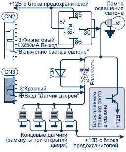
Scheme 6

Scheme 7

Scheme 8

Scheme 9

Scheme 10
Wiring diagrams for hood and trunk sensors (schemes 11-12)

Scheme 11

Scheme 12
Central lock connection diagrams (diagram 13-18)

Scheme 13

Scheme 14

Scheme 15

Scheme 16

Scheme 17

Scheme 18
Connection diagram of the central lock with priority unlocking of the driver's door (diagram 19)

Scheme 19
Connection diagrams for unlocking the trunk (diagrams 20-21)

Scheme 20

Scheme 21
Car security system with two-way communication
This inexpensive model has received recognition from car owners due to its functionality and stability.
The range of the two-way channel between the key fob pager and the car in SCHER-KHAN MAGICAR 3 is up to 1,500 m.
The keyfob features a large, brightly backlit LCD display with easy-to-read pictograms detailing vehicle status. Each action of the system is confirmed by symbols on the key fob-pager screen. It is also equipped with a vibrating alert, so the alarm will not go unnoticed.
Arming and disarming functions are separated to different buttons of the key fob-pager. This allows you to increase the level of protection of the radio control channel. The system also provides protection against unauthorized recording of codes for additional key fobs.
Thanks to the " Free hands» the system allows you to automatically arm and disarm when you move away or approach the car without the help of a key fob-pager.
The system itself is capable of closing electric sunroofs and power windows when arming the car if the car owner forgot to do this. In addition, the SCHER-KHAN MAGICAR 3 provides a covert security mode, in which the alarm signal is transmitted only to the key fob pager.
AT basic configuration only two programmable channels are provided, however, using the SCHER-KHAN AUX-7 module, if necessary, their number can be expanded to seven. In addition, programming of the system functions is possible not only from the key fob, but also with the help of a specialized programmer SCHER-KHAN CM 4.
Specifications
- Key fob-communicator multifunctional, 4-button, with a color liquid crystal display;
- Audiovisual confirmation of executed commands on the display;
- The notification about operation with indication on the display;
- Automatic backlight display;
- Protection against interception of coded packages MAGIC CODE™;
- Separate channels for arming and disarming;
- Long-distance communication up to 1500 m with a microprocessor unit;
- Low battery indication;
- Vibrating call;
- Memory of impacts on the car with visual and sound confirmation;
- Sound and visual reminder modes about receiving an alarm message;
- Economic power supply (one AAA element);
- Remote activation of the "VALET" mode;
- Operative disconnection from the key fob of the shock sensor.
Processing unit
- Accounting for the delay in turning off the cabin light (three modes);
- Event programming to enable additional channels;
- Electronic current protection of all low-current outputs;
- Alarm control power output (two circuits) with separate power circuit;
- Possibility of arming with and without confirmation siren signals;
- Hidden security (possibility of transmitting alarm signals only to the key fob) programming of the central locking algorithm for controlling the “Comfort” function (closing the electric sunroof, power windows);
- Digital algorithms for protecting sensors from false positives;
- Highly sensitive microphone two-level shock sensor;
- Open door alarm warning;
- Personal user code (for emergency shutdown);
- Programming the type of blocking relay (NC or NO);
- Sound warning before automatic arming;
- Security mode without siren signals;
- Output for trunk lock control;
- Outputs for controlling the central locking module;
- Programming the number of pulses for unlocking and locking the central lock;
- Programming the central lock control time;
- Ability to connect negative and positive door sensors;
- Input for negative hood sensor;
- Input for negative trunk sensor;
- Locking and unlocking door locks when the ignition is turned on and off;
- PANIC mode;
- Immobilizer mode;
- "HANDS FREE" mode for automatic arming / disarming when the owner moves away / approaches the car shock sensor.