Contactors or magnetic starters are used to supply power to motors or any other devices. Devices designed to be powered on and off frequently. The connection diagram for a magnetic starter for a single-phase and three-phase network will be discussed further.
Contactors and starters - what's the difference?
Both contactors and starters are designed to close/open contacts in electrical circuits, usually power ones. Both devices are assembled on the basis of an electromagnet and can operate in DC and DC circuits. alternating current different power— from 10 V to 440 V direct current and up to 600 V AC. Have:
- a certain number of working (power) contacts through which voltage is supplied to the connected load;
- a number of auxiliary contacts - for organizing signal circuits.
So what's the difference? What is the difference between contactors and starters? First of all, they differ in the degree of protection. Contactors have powerful arc extinguishing chambers. This leads to two other differences: due to the presence of arc arresters, contactors have big size and weight, and are also used in circuits with high currents. For low currents - up to 10 A - only starters are produced. By the way, they are not produced for high currents.
There's another one design feature: starters are produced in a plastic case; only the contact pads are exposed outside. Contactors, in most cases, do not have a housing, therefore they must be installed in protective housings or boxes that will protect against accidental contact with live parts, as well as from rain and dust.
In addition, there is some difference in purpose. The starters are designed to start asynchronous three-phase motors. Therefore, they have three pairs of power contacts - for connecting three phases, and one auxiliary one, through which power continues to flow to operate the engine after the “start” button is released. But since such an operating algorithm is suitable for many devices, a wide variety of devices are connected through them - lighting circuits, various devices and devices.
Apparently because the “filling” and functions of both devices are almost the same, in many price lists the starters are called “small contactors”.
Design and principle of operation
To better understand the connection diagrams of a magnetic starter, you need to understand its structure and operating principle.
The base of the starter is a magnetic circuit and an inductor. The magnetic core consists of two parts - movable and stationary. They are made in the form of the letters “Ш” with their “legs” facing each other.
The lower part is fixed to the body and is stationary, the upper part is spring-loaded and can move freely. A coil is installed in the slot in the lower part of the magnetic circuit. Depending on how the coil is wound, the rating of the contactor changes. There are coils for 12 V, 24 V, 110 V, 220 V and 380 V. On the top of the magnetic circuit there are two groups of contacts - movable and fixed.

In the absence of power, the springs press out the upper part of the magnetic circuit, the contacts are in their original state. When voltage appears (press the start button, for example), the coil generates an electromagnetic field that attracts the upper part of the core. In this case, the contacts change their position (picture on the right).
When the voltage drops, the electromagnetic field also disappears, the springs push the moving part of the magnetic circuit up, and the contacts return to their original state. This is the principle of operation of an electromagnetic starter: when voltage is applied, the contacts close, and when voltage is lost, they open. Any voltage can be applied to the contacts and connected to them - either constant or alternating. It is important that its parameters are not greater than those declared by the manufacturer.

There is one more nuance: the starter contacts can be of two types: normally closed and normally open. Their operating principle is clear from the names. Fine closed contacts when triggered they turn off, normally open ones close. The second type is used to supply power; it is the most common.
Connection diagrams for a magnetic starter with a 220 V coil
Before we move on to the diagrams, let’s figure out what and how these devices can be connected. Most often, two buttons are required - “start” and “stop”. They can be made in separate housings, or they can be a single housing. This is the so-called push-button post.

Everything is clear with individual buttons - they have two contacts. One receives power, the other leaves it. There are two groups of contacts in the post - two for each button: two for start, two for stop, each group on its own side. There is also usually a ground terminal. Nothing complicated either.
Connecting a starter with a 220 V coil to the network
Actually, there are many options for connecting contactors; we will describe a few. The diagram for connecting a magnetic starter to a single-phase network is simpler, so let's start with it - it will be easier to understand further.
Food, in in this case 220 V, is applied to the coil terminals, which are designated A1 and A2. Both of these contacts are located at the top of the case (see photo).

If you connect a cord with a plug to these contacts (as in the photo), the device will be in operation after the plug is inserted into the socket. In this case, any voltage can be applied to the power contacts L1, L2, L3, and it can be removed when the starter is triggered from contacts T1, T2 and T3, respectively. For example, you can apply to inputs L1 and L2 constant pressure from a battery that will power some device that will need to be connected to outputs T1 and T2.

When connecting single-phase power to the coil, it does not matter which output is supplied with zero and which with phase. You can switch the wires. Even most often, the phase is supplied to A2, since for convenience this contact is located on the bottom side of the housing. And in some cases it is more convenient to use it and connect the “zero” to A1.
But, as you understand, this scheme for connecting a magnetic starter is not particularly convenient - you can also supply conductors directly from the power source by building in a regular switch. But there is much more interesting options. For example, you can supply power to the coil through a time relay or light sensor, and connect a power line to the contacts. In this case, the phase is connected to contact L1, and zero can be taken by connecting to the corresponding coil output connector (in the photo above it is A2).
Diagram with start and stop buttons
Magnetic starters are most often installed to turn on an electric motor. It is more convenient to work in this mode if there are “start” and “stop” buttons. They are connected in series to the phase supply circuit to the output of the magnetic coil. In this case, the diagram looks like the figure below. note that

But with this method of switching on, the starter will only operate as long as the “start” button is held down, and this is not what is required for long work engine. Therefore, a so-called self-catching circuit is added to the circuit. It is implemented using auxiliary contacts on the starter NO 13 and NO 14, which are connected in parallel with the start button.

In this case, after the START button returns to its original state, power continues to flow through these closed contacts, since the magnet has already been attracted. And power is supplied until the circuit is broken by pressing the “stop” key or by triggering a thermal relay, if there is one in the circuit.
Power for the motor or any other load (phase from 220 V) is supplied to any of the contacts marked with the letter L, and is removed from the contact marked T located underneath it.
It is shown in detail in what order it is better to connect the wires in next video. The whole difference is that not two separate buttons are used, but a push-button post or push-button station. Instead of a voltmeter, you can connect a motor, pump, lighting, or any device that operates on a 220 V network.
Connecting a 380 V asynchronous motor via a starter with a 220 V coil
This circuit differs only in that three phases are connected to contacts L1, L2, L3 and three phases also go to the load. One of the phases is energized to the starter coil - contacts A1 or A2. In the figure this is phase B, but most often it is phase C as it is less loaded. The second contact is connected to the neutral wire. A jumper is also installed to maintain power supply to the coil after the START button is released.

As you can see, the scheme has remained virtually unchanged. Only it added a thermal relay that will protect the engine from overheating. The assembly procedure is in the next video. Only the assembly of the contact group differs - all three phases are connected.
Reversible circuit for connecting an electric motor through starters
In some cases, it is necessary to ensure that the motor rotates in both directions. For example, for the operation of a winch, in some other cases. A change in the direction of rotation occurs due to phase reversal - when connecting one of the starters, two phases must be swapped (for example, phases B and C). The circuit consists of two identical starters and a button block, which includes a common “Stop” button and two “Back” and “Forward” buttons.

To increase safety, a thermal relay has been added, through which two phases pass, the third is supplied directly, since protection in two is more than enough.
Starters can be with a 380 V or 220 V coil (indicated in the specifications on the cover). If it is 220 V, one of the phases (any) is supplied to the coil contacts, and “zero” from the panel is supplied to the second. If the coil is 380 V, any two phases are supplied to it.
Also note that the wire from the power button (right or left) is not fed directly to the coil, but through the permanently closed contacts of another starter. Contacts KM1 and KM2 are shown next to the starter coil. This creates an electrical interlock that prevents two contactors from being supplied with power at the same time.

Since not all starters have normally closed contacts, you can take them by installing additional block with contacts, which is also called a contact attachment. This attachment snaps into special holders, it contact groups work together with groups of the main building.
The following video shows a diagram for connecting a magnetic starter with reverse on an old stand using old equipment, but general order action is clear.
In the presence of sufficient quantity free time domestic motorists often prefer to repair their " iron horses" on one's own. In this regard, the vehicle ignition system is no exception. Experienced motorists know how to connect the ignition coil themselves, without resorting to the help of specialists from service shops.
However, similar works are not too different high level difficulties. However, as practice shows, producing renovation work vehicle ignition systems associated with inductor coil repair, even experienced car owners often forget about which wires with which insulation color should be connected to which terminals. In the future, this may cause certain difficulties during installation.

Step-by-step instructions on how to connect the ignition coil with your own hands:
1. First of all, it is necessary to remove the failed inductor. Next, a new ignition coil is installed in the vacant space. There is nothing complicated in this process, but many motorists, when installing a new element in engine compartment What can be confusing is what color wire should be connected to which terminal.

2. For those car owners who have not yet been able to remember exactly what color wires to connect to which terminals, just in case, let us remind you: an insulated wire is always connected to the “+” terminal of the ignition system coil Brown- it should come from the ignition switch.

3. Accordingly, it is necessary to connect a wire with black insulation to terminal “K” - it connects the inductor coil and the terminal of the breaker-distributor of the car’s ignition system.
4. Final stage: carefully tighten the nuts on the coil and distributor terminals. The ignition coil has been connected, your vehicle again ready for further use.
Today we will look at the design and diagrams of ignition systems for VAZ cars of all major models. Since carburetor versions of VAZ are practically history, let us dwell in detail on the ignition systems injection cars. Their ignition system is based on a module electronic ignition. We also recommend that you carefully consider the choice of spark plugs and the quality of high-voltage wires, because the quality of the spark and, accordingly, the operation of the ignition system as a whole will depend on them. The information is intended as a reference for self-repair auto.
Pinout and diagram of the VAZ ignition coil
Pinout of ignition coil modules various models car of the VAZ family:
Ignition VAZ 2101

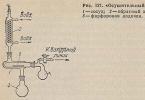
1 – generator; 2 – ignition switch; 3 – ignition distributor; 4 – breaker cam; 5 – spark plugs; 6 – ignition coil; 7 – battery.
Ignition VAZ 2106

1 – ignition switch; 2 – fuse and relay block; 3 – EPHH control unit; 4 – generator; 5 - solenoid valve; 6 – microswitch; 7 – spark plugs; 8 – ignition distributor; 9 – ignition coil; 10 – battery.
Ignition VAZ 2108, 2109


Ignition VAZ 2110


Ignition VAZ 2111


Ignition VAZ 2112


Ignition VAZ 2114

Diagram of a non-contact ignition system: 1 – non-contact sensor; 2 – ignition distributor sensor; 3 – spark plugs; 4 – switch; 5 – ignition coil; 6 – mounting block; 7 – ignition relay; 8 – ignition switch.

How to check the ignition coil of a VAZ
If the ignition coil is faulty, the engine will not start. A characteristic feature the faulty coil is its elevated temperature with the ignition off. This is easy to determine by touch.

Signs faulty module ignitions can be as follows:
- hesitant engine starting or failure to start;
- failures during sudden changes in speed;
- high fuel consumption;
- two cylinders do not work, the engine is feverish;
- lack of dynamics;
- a sharp drop in power;
- drop in power and thrust after warming up.
These symptoms may not only be caused by the ignition module. To determine the malfunction, it is enough to spend a few minutes diagnosing spark plugs, high-voltage wires and caps. This will eliminate the remaining elements of the ignition system and make sure that it is the ignition module that is faulty.
Checking the ignition coil is performed in one of 2 ways. The simplest one is to remove the central wire from the breaker-distributor, bring it to the motor housing and turn it with the starter, and a running spark should appear. After this, we check the energy supply to a separate spark plug, for which we unscrew the working spark plug, bring its contact to ground and attempt to start the engine. In this case, the spark should come from the wire to ground. If it is absent, the reason will be a malfunction of a system element such as the ignition coil.

To check the module in the second way, we only need a multimeter, then follow the step-by-step instructions:
- We check the power supply and the presence of pulses supplied from the ECU. We check the power between the central terminal (15) of the wire block connected to the module and the engine ground. When the ignition is on, the voltage should not be less than 12 V. Otherwise, either the battery is dead or the ECU does not work.
- We check the pulses from the ECU on the wiring block. We install one tester probe on connector 15, the second on the far right, then on the far left. The assistant cranks the engine with the starter, and at this time we record short-term voltage surges with a tester. If there are no impulses from the ECU, it is he who is to blame.
- We check the resistance on the secondary windings of the coils. We put the tester in resistance measurement mode and measure it at the high-voltage terminals of the module cover. Between pins 1 and 4 and pins 2-3, the resistance should be 5.4 kOhm. Otherwise, the module must be replaced.
- We check the resistance of the primary windings between contacts 15 and the rightmost, then the leftmost terminals. Nominal - 0.5 Ohm. Deviation is not allowed.
- Check the module for a short circuit. In ohmmeter mode, install one multimeter probe on the central terminal, the second on the metal body. There shouldn't be any resistance. If the device detects at least some resistance (other than unity or infinity), the module must be replaced.
Connecting and replacing VAZ short circuit
The procedure for removing and installing the ignition coil on old VAZ models:
- First disconnect the center high voltage wire, leading to the distributor (ignition distributor).
- Disconnect all power wires from the coil contacts. Since they are fastened with nuts, you will need an 8 wrench for this.
- If you don’t know which wires to connect to which connector later, it is better to immediately remember or mark them somehow, so that later during installation you can connect them correctly.
- Unscrew the coil housing. It is attached to a clamp (clamp), which is pressed to the car body with two nuts.
- After the work has been done, you can remove the ignition coil and replace it if necessary.
For new type VAZ cars:
- We remove the negative terminal from the battery.
- Remove the top protective cover engine. If the engine volume is 1.5 liters, then this part is missing and this step is skipped.
- We remove the high-voltage wires from the coil.
- Now, using a 13mm wrench, unscrew the two fasteners.
- Using a 17mm wrench, loosen one bolt securing the coil.
- We take out the module.
- Use a hexagon to unscrew the coil from the holder.
- Assembly is carried out in reverse order.

Special attention It is worth paying attention to the connection, since high-voltage wires must be located in the strict order provided for by the design. If this is not done, the car will stall or the engine may not start at all.
Replacing the ignition coil on a VAZ is quite simple. Even a novice motorist can do this in his garage, and if everything seems too complicated, contact a car service center. Particular attention should be paid to the choice of product, since this will determine how well the engine and ignition system will work.
VAZ models 8 and 16 valves
Despite the similarity in engine design, the ignition system of the 1.5-liter injection 16-valve engine differs from the 1.6 16-valve engine. The 1.6 liter engine uses an electronic non-contact ignition system with individual coils on every candle. Therefore, there was no need for an ignition module. Such a system is more reliable and cheaper to operate, since if one coil fails, there is no need to replace the entire module.

On 16 valve injection engine VAZ 2112 with a volume of 1.5 liters used the same contactless system ignition, as on the 8-valve engine, but a different ignition module was installed. His Catalogue number 2112-3705010. The design of the module remains the same - two ignition coils (for cylinders 1-4 and 2-3) plus switch keys in a single block. The spark is supplied to the cylinders in pairs using the idle spark method. This means that sparking occurs in two cylinders simultaneously - in one on the compression stroke (working spark), in the second on the exhaust stroke (idle spark).
Video on repairing KZ VAZ
Wires are an essential part of the ignition system of any modern car. There are features of their connection depending on the car model and its design. Let's find out how to connect the ignition wires on your car.
How are ignition wires different from regular ones?
ATTENTION! A completely simple way to reduce fuel consumption has been found! Don't believe me? An auto mechanic with 15 years of experience also didn’t believe it until he tried it. And now he saves 35,000 rubles a year on gasoline!
So, the ignition system wires are otherwise called high-voltage or armored wires. This is an essential part of the system through which electrical impulses are transmitted. At the moment when voltage is applied to the spark plugs, the combustible mixture (FA) ignites. Thanks to this, a new cycle of operation of the internal combustion engine begins.
The design of armored wires, in contrast to conventional ones, differs markedly. So, in addition to the copper core, which is responsible for conducting current and protection (insulation), they also contain tips and plastic caps.
What are metal tips and protective caps for? The former successfully perform the functions of contacts, the latter protect the wires from dirt and dust. In addition, the armored wire ends are manufactured to fit precisely into the spark plug sockets and into the holes on the distributor.
Important point. The resource and service life of the armored wires as a whole depends on how well the tips are made.
When choosing between certain models of armored wires, you should keep in mind two important points. The first is resistance, and the second is their breakdown voltage. Relatively best transfer electric pulse is, of course, associated with a low resistance value. As for the second value, it directly affects the resistance to electrical breakdowns and short circuits.

The table below shows various resistance values of armored wiring from manufacturers Tesla, Caesar, Elephant and others. Of course, Tesla has received the most approval from car owners around the world. And along with good resistance, they are also distinguished by an excellent breakdown voltage indicator.
The price for a set of Tesla armored wiring does not, as a rule, exceed 500-600 rubles.
| Manufacturer | Resistance on cylinder No. 1 (kOhm) | Resistance on cylinder No. 2 | Resistance on cylinder No. 3 | Resistance on cylinder No. 4 | Breakdown voltage (kV) |
|---|---|---|---|---|---|
| Tesla | 3..27 | 4..16 | 5..02 | 6..26 | 50 |
| Cezar | 3..1 | 3..53 | 4..23 | 5..34 | 50 |
| Finwhale | 1..95 | 2..18 | 2..6 | 3..42 | 50 |
| Ween | 6..17 | 6..57 | 7..52 | 9..89 | 35 |
| Slon | 4..24 | 4..74 | 5..19 | 7..6 | 50 |
How the connection is made
So, the order of connecting the armored wires must be consistent. This is extremely important, because each cylinder of the internal combustion engine must have its own wire. The ignition coil distributor has corresponding sockets that are numbered. Everything is clearly provided for: it will be very difficult to confuse one or another wire connecting the spark plugs with the distributor-coil.
As mentioned above, the connection diagram for the armored wiring depends on a certain model car. For example, the car of the fourteenth VAZ model was equipped with two types of armored wiring: the version before 2004 and after. The difference is due to the fact that before this year 4-pin distributor coils were installed, after which 3-pin distributors were installed.
The photo below shows the layout of armored wiring on a VAZ before 2004 and after


In order not to confuse anything during the process of connecting armored wires, it is recommended to adhere to the following:
- Disconnect the battery terminals;
- Remove the old armored wires from the ignition module;
- Connect new ones according to the connection diagrams;
- Insert the battery terminals into place;
- Start the engine.
If the engine starts easily, then everything was done correctly. When installing the wiring, it is recommended not to connect them together with plastic clamps, but to use the comb holder included in the kit.

And finally, let’s say that armored wires should be changed regularly, after a certain period of time. For example, on the same VAZ 2114 - every 30,000 km.
Car ignition is a set of devices and instruments that ensure ignition of the combustible mixture in the cylinders in accordance with the operating modes of the engine. I'll tell you what this coil is, how important it is correct work for the ignition system. Let's look at what the ignition coil connection diagram looks like, and what it actually consists of.
The ignition coil is a transformer whose operation is aimed at increasing direct current. Its main task is to generate high-voltage current, without which arson is not possible. fuel mixture. Current from the battery flows to the primary winding. It consists of one hundred or more turns of copper wire, which is insulated with a special substance. Low voltage voltage (twelve volts) is supplied to the edges. The edges are connected to the contacts on its cover. On the secondary, the number of turns is much greater (up to thirty thousand) and the wire is much thinner. A high voltage is created on the secondary (from twenty-five to thirty thousand volts) due to the thickness and number of turns.
It is connected like this: the contact of the secondary circuit is connected to the negative contact of the primary, and the second contact of the winding is connected to the neutral terminal on the cover, this wire is the transmitter high voltage. A high-voltage wire is connected to this terminal, the other edge of which is connected to the neutral terminal on the cover. To create a strong magnetic field, an iron core is placed between the windings. The secondary winding is located inside the primary.
Structurally, the ignition coil consists of the following elements:
- Insulator;
- Frame;
- Insulating paper;
- Winding (primary and secondary);
- Insulating material between windings;
- Primary winding output terminal;
- Contact screw;
- Central terminal;
- Lid;
- Output terminal on the primary and secondary windings;
- Center terminal spring;
- Primary winding frame;
- External insulation on the primary winding;
- Mounting bracket;
- External magnetic circuit and core.
 So, briefly about the principle of operation.
A high voltage current appears on the secondary winding, and at this moment a low current passes through the primary winding. Thus, a magnetic field arises, as a result of which a high voltage current pulse appears on the secondary winding. At the moment when it is necessary to create a spark, the contacts of the ignition breaker open, and at this moment the circuit opens on the primary winding. A high-voltage current arrives at the central contact of the cover and rushes into the contact near which the slider is located.
The connection diagram is quite simple for a specialist, but it is easy for a beginner to get confused in it.
When connecting the coil to the car’s ignition system, in principle, you should not have any difficulties if, during preliminary dismantling, you marked or remembered which wires are connected where. If you have not done this, then I will tell you how to do it. The connection is made as follows: you need to connect the brown wire to the positive terminal. Usually, the positive terminal is indicated by a “+”, but if you do not see a sign, then you need to find it yourself.  To do this, you can use an indicator screwdriver. I think you know how to use it. It is important that before connecting, clean all contacts and check the wires for serviceability. The black wire is connected to the second terminal (terminal “K”). This wire is connected to the voltage distributor (distributor).
The connection diagram of several elements is as follows. TO on-board network one end of the coil is connected. The second end is connected to the next one, and in this way every last one is connected. The remaining free contact of the last coil must be connected to the distributor. And a common point is connected to the voltage switch. Once all mounting bolts and nuts are securely tightened, the replacement can be considered complete. 
Some important tips before replacing and connecting. If you have determined for yourself that the problem with the ignition malfunction is the coil, then it is better to immediately purchase a new one and connect it (the diagram is shown above).
This way you will be sure that now there are no problems with it, since it is completely new.
If you find any defects on the surface, it is better to replace it immediately. Otherwise, it will work for some more time and you will have to return to this topic again. It’s better to play it safe in advance so as not to stop somewhere on the road. After all, ignition of a car does not forgive mistakes and negligence. When repairing a car, especially when it comes to the ignition system, you need to be extremely careful in your actions. So how can you encounter high voltage wires
. Therefore, when replacing or performing repairs, you must follow safety regulations.
Video “Ignition coil connection diagram”