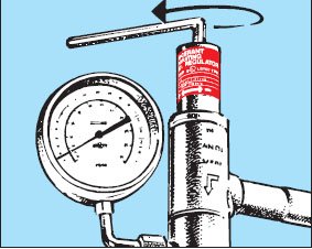
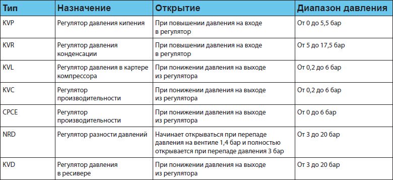
The factory setting of the KV pressure regulators should be used as the basis for setting them. factory setting of each regulator is determined by the distance from the cut of the adjusting sleeve to the head of the adjusting screw (see figure).
The table shows the factory setting pressure for each type of regulator and the distance X to the head of the adjusting screw to which this pressure corresponds, as well as the change in setting pressure when the screw is turned one full turn.
As delivered, the KVP regulator is set to 2 bar. Turn the adjusting screw to the right to increase the pressure, to the left to decrease it. After a certain period of operation of the regulator as part of the installation, it is required to fine-tune it. To carry out this operation, you must use a manometer.If the KVP controller is used to defrost an evaporator, fine tuning is carried out at the minimum per system. After each adjustment, do not forget to install a protective cap on the adjusting sleeve.
The factory setting of the regulator corresponds to the pressure at which the valve begins to open or to the pressure at which it is completely closed. To protect the compressor, the regulator must be set to the maximum allowable compressor.
This setting must be carried out according to the readings of the pressure gauge installed on the suction line of the compressor.
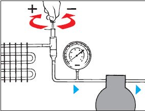
KVR condensing pressure regulator + NRD check valve
In refrigeration units equipped with KVR + NRD regulators, the KVR setting must provide the correct receiver pressure.The pressure in is typically 1.43.0 bar (pressure drop across the NRD valve) higher than the pressure in the receiver. If this difference is unacceptable, a KVR regulator must be used with a KVD - receiver pressure valve.
It is advisable to adjust the regulators in the cold season.

The KVD regulator is then adjusted to the receiver pressure, for example so that the receiver pressure is about 1 bar below the condensing pressure. This adjustment is made using a manometer. Adjustment is desirable to carry out in the cold season.
To set the condensing pressure regulator during the warm season, one of the following methods is suggested:
- In a newly installed installation, when using KVR and KVD with factory setting (10 bar), this pressure must be taken as the base pressure and, taking into account the dependence of the setting pressure on the number of turns of the adjusting screw, adjust the pressure to the required value.
- In an existing installation (setting pressure of KVR and KVD regulators is unknown), first use a pressure gauge to find the reference point, and then turn the adjusting screw to set the desired setting pressure.

Pressure regulators have a simple design, which includes two main components - a responsive and an actuating element. The first is represented by a sensitive element (membrane), which compares the current pressure of the working medium with the sensor signal. The second component is made in the form throttle valve- on command, it closes the flow area on desired level. The working nodes of the regulator are interconnected by an executive connection. All proposed devices have a durable all-metal housing with side connections for installation in a pipeline. Individual models equipped with additional outputs for connecting various devices.
Principle of operation
Direct acting gearboxes supplied by NEMEN operate directly under the influence of the medium itself. The user only installs control valves and sets the optimal pressure parameters (maximum and minimum), within which the device will stabilize. Responding to fluctuations in the flow force, the regulator automatically changes the position of the damper to open or close the flow area to required level. As a result of its operation, the transported medium enters the system in a strictly metered manner, which makes it possible to avoid sudden pressure surges and its consequences.
Main types of products
All pressure regulators have approximately the same device layout. At the same time, they also have differences. Depending on the model, the products can be equipped with a valve or damper, a spring or pneumatic control element, a diaphragm or a piston. The main classification is carried out in the direction of stabilization:
- up to yourself- adjust the flow force in the area located in front of the valve;
- after myself- adjust the parameters of the working medium in the circuit behind the valve;
- universal- correct differences in two directions, determining the difference in the indicator at the points of connection to the return and direct pipelines.
Regulator Specifications
Modern gearboxes are produced in a wide range, which includes solutions for piping systems different type and appointments. In our catalog you can find pressure regulators with such parameters.
- Working environment- water, steam, oil products, gas, air.
- Mounting method- welding, threaded, flanged.
- Section diameter- from 15 to 200 mm.
- Max pressure- from 10 to 40 bar.
- The temperature of the transported substance- from -5 to +240 °С.
Benefits of Direct Acting Regulators
- No need to use foreign source nutrition.
- High speed of response to changes and accuracy of stabilization.
- Easy installation and adjustment of the operating parameters of the device.
- High-quality optimization of the functioning of the entire system.
- Reliability of protection of the pipeline and connected equipment.
1. Purpose, device and operation of the pressure regulator 3RD.
For automatic switching compressor from operating mode to idle, or vice versa, a 3RD pressure regulator is used on diesel locomotives. The ZRD pressure regulator is used on diesel locomotives with a compressor driven by a diesel engine.
Fig.1. 1-body, 2-shut-off valve, 3-seat, 4-spring, 5-stem, 6-filter, 7-locknut, 8-stem nut, 9-stem, 10-spring, 11-seat, 12-valve, 13-spring, 14-closing valve, 15-socket, 16-attachment plate. A, B, V-cameras, A1, A2, A3, A4, B1, B2, B1, B2, B3, E, E1, E2 channels
The pressure regulator (Fig. 1) consists of a body 1 and a counter plate 16, to which pipes with a diameter of 1/2˝ are connected from the main reservoir of the GR and a diameter of 1/4˝ from the unloading mechanism of the PK installed on the suction valves of the compressor.
In building 1 right side in socket 15 there is a switching valve 14, loaded from above with spring 10, and on the left side in socket 3 -
shut-off valve 2, loaded with spring 4. From below into slot 15
a seat 11 with a valve 12 and a spring 13 is screwed in. At the upper threaded ends of the rods 9 and 5 there are nuts 8 for adjusting the springs 10 and 4. When the rod 9 is rotated, the nut 8 moves along the thread and changes the pressure of the spring 10, after which the rod is fixed with a lock nut 7.
The spring 10 of the switching valve 14 is adjusted to a pressure of 0.75 MPa (7.5 kgf/cm2), and the spring 4 of the switching valve 2 is adjusted to a pressure of 0.85 MPa (8.5 kgf/cm2). In the middle part of the body 1 there is a filter 6 filled with horsehair.
The cavity of the regulator housing is divided by internal walls into three chambers: chamber A of the main tank (GR), chamber B of the switching pressure and chamber C of the switching pressure.
Job. Air from the main tank enters chamber A and through filter 6 through channels A1 and A2 under the switching valve 2, and through channel A3 - under check valve 12. At this time, chamber B is connected by channels B1, B2, C3 and C1 to chamber C, which is connected by channel B2 to the atmospheric opening At. Chambers B and C and the chamber above the diaphragm of the compressor unloading mechanism are in communication with the atmosphere.
As soon as the pressure in the main tank and in channel A2 increases to the value to which the spring 4 is adjusted (8.5 kgf / cm2), valve 3 will move away from its seat under the action of air pressure on a small area. After that, the air pressure will spread to the entire area of the valve 2 (shear), as a result of which the lift valve will clear. When valve 2 is lifted, the following will happen:
Air from the main tank through channels A1 and A2 will enter channel E and then under valve 14, the spring of which is adjusted to a pressure of 7.5 kgf / cm2;
The valve 14 will rise and close the hole B1, i.e. will stop the communication of chamber B with chamber C, leaving the latter communicated with the atmosphere Am;
The check valve 12 will open, and air from the main tank will flow through channels A1 and A2 and holes E1 and E2 into channel A4 and then to the unloading valves of the compressor;
At the same time, air through channels B2 and B1 will enter chamber B, and valve 2 will disconnect channels A2 and E.
After valve 2 is seated on seat 3, the air from the main reservoir will flow through channel A1 to the unloading valves of the compressor only through channel A3, valve 12, channel A4, and the compressor will start to idle. As soon as the pressure in the main tank drops to 7.5 kgf / cm2, to which the spring 10 is adjusted, the valve 14 will move down and seat the check valve 12 on the seat 11, and the following will happen:
Channel A3 will be blocked by valve 12, and the communication of the main tank (channel A1) with channel A2 and the valve of the unloading mechanism will stop;
Chamber B will communicate with chamber C through channels B1, B2, C3 and C1, as a result of which the air from the valves of the unloading mechanism and chamber C will be released into the atmosphere, and the pressure regulator will take the position shown in Fig. 1.
In this position, it will be up to the pressure to which the spring 4 is adjusted (8.5 kgf / cm2). To turn off the compressor, rotate the rod 5 counterclockwise until valve 2 is seated on the seat. Rotating the rod 9 clockwise, regulate the moment of switching on the compressor. After adjustment, the rods 5 and 9 are fixed with lock nuts 7.
On two-section diesel locomotives, the pressure regulator that controls the operation of the compressors of both sections is turned on only on one section, and on the other it is turned off by closing the disconnecting valves on the pipelines that communicate it with the GR and unloading devices.
When conducting current repair do the following:
- The filter must be disassembled, the packing and mesh washed and dried. worn out
Replace the packing with a new one, previously lightly impregnated with oil.
Lapping surfaces of valves and their seats, having leaks or wear,
should be cleaned and rubbed.
Check the gap in the guide sleeve between the switching and switching
valves, which should be within 0.005-0.050 mm. With larger valve clearance
replaced with a new one, while the gap between the bushing and the valve should be within 0.005-0.020
Replace broken or loose adjusting springs.
After repair and assembly, the pressure regulator is tested for valve tightness
pressure 10 kgf/sq.cm. It is allowed to form a soap bubble on the weekend
holes holding it for at least 5 s.
Finally, the pressure regulator is adjusted on the locomotive to turn off when
pressure in the main tanks of 8.5 kgf / sq. cm and to turn on at 7.5 kgf / sq. cm with shutdown at
0.2 kgf/sq.cm
2. Purpose, device and operation of the support-return device on a diesel locomotive 2TE116
The support-returning device of the diesel locomotive perceives the weight of the entire overbogie structure, ensures the stable position of the bogie under the locomotive during its movement, as well as smooth entry into curves and the creation of the necessary forces that return the locomotive body to its original position when moving it relative to the bogies when moving in curves. To equalize the loads from the wheelsets of the bogies on the rails, the front supports are located around the kingpin along a circle with a radius of 1632 mm, the rear ones with a radius of 1232 mm. The overbogie structure of the diesel locomotive rests on the bogie frame through four combined supports (Fig. 93), each consisting of two stages: the lower rigid stage is a roller bearing, the upper elastic one is a block containing seven rubber-metal elements (RME).
The roller bearing consists of a cast housing 19, which is installed on the sidewall of the bogie frame at a tangent to a circle with a radius equal to the bogie turning radius, ensuring its rotation on the rolling bearings, the lower base plate 16, the rollers 17 interconnected by clips 75, and the upper support plates 7. The rollers rotate in * cages with non-metallic bushings 18, which are bearings for the rollers. The entire movable support system (rollers with cages, upper support plate 1a; during movement, it is guided by wear-resistant plates welded to the side walls of the housing, made of steel 65G. High contact stresses arise on the rolling surface of the rollers and base plates, so the rollers are made of steel 40X and subjected to surface hardening to a depth of 1.5-3 mm.The base plates are pre-cemented, then the surface is hardened.
The rolling surfaces of the base plates are made inclined - the angle of inclination is 2°. On a straight section of the path, the rollers occupy a middle position between the inclined planes. When the bogie rotates relative to the body, the rollers roll onto inclined surfaces supports. In this case, horizontal forces arise that create a restoring moment on the supports, which contributes to the return of the trolley to starting position. In addition to the restoring forces, when the bogies turn in the support, friction forces and a moment of friction forces arise, which helps to reduce the wobbling of the bogies. The roller bearing stroke is ±80 mm.
The elastic stage of the combined support contains seven elastic elements 5 located between the support ring 4 of the roller device on the bogie and the support ring 6 on the locomotive body. The elastic set is limited by a conical cup 8 with a gap exceeding the largest body offset that occurs when the locomotive passes a curve with a radius of 125 m. The elastic element 5 is
rubber washer vulcanized to steel plates with stamped ring hooks to prevent transverse shift of elements in the set and in connections with base plates.

Rice. 1. Combined support: 1, 16 - upper and lower base plates; 2 - cover; 3 - bolt; 4, 6 - support rings; 5 - elastic element; 7 - shims; 8 - conical glass; 9, 10 - clamps; 11 - case; 12 - cork; 13 - drain plug; 14 - bogie frame; 15 - clip; 17 - roller; 18 - bushing; 19 - roller bearing housing
Each set of rubber-metal elements of the combined support is subjected to bench calibration in height (K dimension), taking into account the dynamic load of 140 kN (14 tf), as well as checking the quality of the elements. The vertical stiffness of the set of rubber-metal elements is 55-105 N/m (550 kgf/mm), and the horizontal stiffness is 2-105 N/m (20 kgf/mm). Sets of one trolley should not differ from each other in height by more than 1 mm. Compliance with this requirement is achieved by installing shims 7 under the supporting part of the body.
The inner cavity of the roller bearing is filled with axial oil. Oil is poured into the support through the hole closed by plug 12, and the oil is drained and the support flushed through the hole closed by plug 13. The roller bearing is closed by cover 2, which prevents oil from splashing out of the support by its movable system. To prevent foreign objects and atmospheric precipitation from entering the combined support, it is closed with a cover 11, fixed on the roller support body and protective
body ring with clamps 9 and 10.
Each combined support with respect to the center of rotation of the bogie is installed so that the roller part ensures the rotation of the bogie and the restoring moment, and the transverse movement of the body (relativity) is achieved due to the transverse shift of each set of rubber-metal elements. The maximum shift of a set of rubber-metal elements is +45 mm. The elastic support of the body makes it possible to obtain an additional deflection of up to 20 mm in the spring suspension of the locomotive and thereby improve the dynamic and strength characteristics running gear locomotive crew.
The repair of the support-returning device is carried out when the bogie is rolled out from under the diesel locomotive and suspended. Damaged parts are replaced. After carrying out the work, 30 liters of axle oil are poured into the device. In further operation, the device is lubricated through grease fittings with LRW grease.
type RD-MMANUAL
RD-M ______00.00.00 RE
Introduction…………………………………………………………….3
1. Description and operation of the product………………………………………..3
1.1 Purpose……………………………………………………...3
1.2 Specifications …………………………………4
1.3 Composition of the product ……………………………………………………7
1.4 Device and principle of operation ………………………………..7
1.5 Measuring instruments …………………………………………… 10
1.6 Marking …………………………………………………….10
1.7 Packaging ………………………………………………………..11
2. Intended use ……………………………………………………………………11
2.1 Operating limits …………………………………………………………………………………………………………………………………………………………………………………………..11
2.2 Preparing the product for operation …………………………………….11
2.3 Using the Product …………………………………………..13
13
2.3.2 Maintenance ……………………………… 13
2.3.3 Possible malfunctions and ways to eliminate them …14
2.3.4 Indication of security measures ………………………………………………………………15
3. Rules for storage and transportation ………………………… 15
4. Disposal …………………………………………………………………………………15
The operation manual contains information about the purpose of the technical parameters, characteristics, design features, techniques and methods for the safe operation of gas pressure regulators of the RD-M type.
Persons at least 18 years of age who have knowledge of the design and principle of operation of gas pressure control devices, as well as those who have undergone introductory and special instruction in the operation of pressure vessels and have a special permit for this, are allowed to work on the operation, maintenance and repair.The operating manual applies to all standard sizes of RD-M regulators produced by the manufacturer:
RD-M 100/25; RD-M 63/25;
RD-M 100/40; RD-M 63/40;
RD-M 100/50; RD-M 63/50;
RD-M 100/80; RD-M 63/80;
RD-M 100/100; RD-M 63/100;
RD-M 100/150; RD-M 63/150.
In connection with permanent job enterprises to further improve the product in order to increase its reliability, and other consumer qualities, some changes may be made to the design that are not reflected in this manual.
1. Description and operation of the product
1.1 Purpose of the product
1.1.1 The gas pressure regulator type RD-M (hereinafter referred to as the regulator) is intended for automatic regulation of gas pressure "after itself" at gas pipeline facilities high pressure(gas distribution stations, gas purification and drying plants, gas fields, compressor stations, etc.)
1.1.2 By the manufacturer, regulators are manufactured for nominal pressure Ru=10.0 MPa with nominal bore DN=25mm, DN=40mm, DN=50mm, DN=80mm, DN=100mm, DN=150, as well as regulators for nominal pressure Ru=6.3 MPa with nominal bore DN=25mm, DN=40mm, DN=50mm, DN=80mm, DN=100mm, DN=150.
Examples of designation of regulators:
RD-M 100/100 - regulator with a nominal pressure of 10 MPa (100 kg / cm 2) and a nominal bore of 100 mm;
RD-M 63/100 - a regulator with a nominal pressure of 6.3 MPa (63 kg / cm 2) with a nominal bore of 100 mm.
1.2 Specifications
| Controller version |
||||||||||||
| Name of the main parameters | RD-M 63/25 | RD-M63/40 | RD-M 63/50 | RD-M 63/80 | RD-M 63/100 | RD-M 63/150 | RD-M100/25 | RD-M100/40 | RD-M100/50 | RD-M100/80 | RDM100/100 | RDM100/150 |
| Nominal diameter, mm | ||||||||||||
| Maximum inlet pressure, MPa (kgf / cm 2) | 6,3 (63) | 10,0 (100) |
||||||||||
| Working environment | Natural gas |
|||||||||||
| Upper setting limit, MPa (kgf / cm 2) | 1,6 (16) |
|||||||||||
| lower limit settings, MPa (kgf / cm 2) | 0,10 (1,0) |
|||||||||||
| Pipe connection type | Flanged according to GOST 12821-80 version 3 |
|||||||||||
| Installation position on the pipeline | vertical |
|||||||||||
| Permissible outlet pressure fluctuations | ± 5% of nominal value with inlet pressure fluctuations of ±25% |
|||||||||||
| Overall and connecting dimensions | See fig.1 |
|||||||||||
Fig.1 Dimensional diagram and slinging diagram
When defining consumable characteristics regulators, you must use the nomogram shown in Fig. 2 with an example of working with it.
Legend:
P 1 (kgf / cm 2) - pressure at the inlet of the regulator
P 2 (kgf / cm 2) - pressure at the outlet of the regulator
DN (mm) - conditional passage
Q (m 3 / h) - consumption

Fig.2
Nomogram for determining flow characteristics of regulators
according to their consumption characteristics
Example: Determine the required conditional passage of the regulator, if, according to the operating conditions, P 1 = 30 kgf / cm 2; P 2 \u003d 5 kgf / cm 2; flow required Q = 10000 m 3 /h
We find the difference P 1 - P 2 \u003d 30 - 5 \u003d 25 kgf / cm 2, from point 5 on the scale "P 2" of the nomogram we draw a line in point 25 on the scale "(P 1 - P 2)". At the intersection with the vertical line "C" we mark point A. We connect point A and point 10000 of the "Q" scale. On its continuation, at the intersection with the “Du” scale, we find the necessary conditional passage of the regulator and take the nearest larger one.
Similarly, knowing the Du of the regulator, it is possible to determine the approximate gas flow rate on the Q scale.
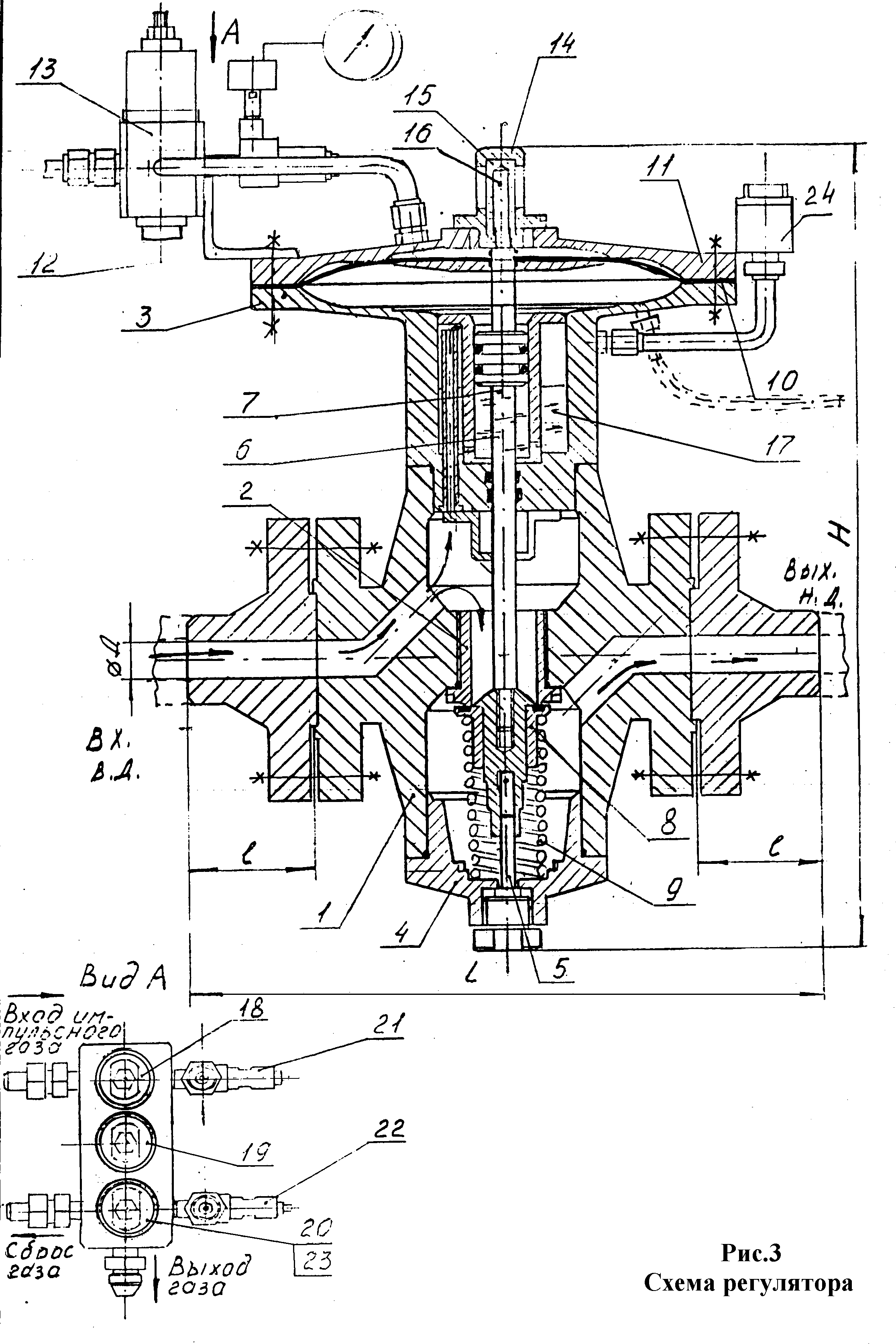
Product composition
1.3 The regulator includes: an actuator with critical flanges and a control unit consisting of regulators-setters of the first and second reduction stages, a check valve, a command device and two throttles for turning off pressure gauges.
The device and principle of operation of the regulator.
1.4.1 Composition of the regulator
The regulator consists of the following main elements (Fig. 3) of the body (1) into which the seat (2) is screwed on the thread, screwed (at regulators RD-M 63/25 and RD-M 63/50) stand (3) and bottom cover (4). In regulators RD-M 63/100 and RD-M 6.3/150, the stand and bottom cover are attached to the body with pins. A guide pin (5) is installed in the bottom cover (4). In the rack (3) there is a piston with a rod (7), on the lower ring of which are installed: a valve (8) based on a spring (9), and on the upper membrane (10) clamped between the rack (3) and the top cover (11 ).Using the bracket (12), the control unit (13) is attached to the post. AT top cover the glass (14) with the glass (15) of the valve position indicator (16) is also screwed in.
Inside the rack (3) there is a cavity (17) filled with oil or other liquid, depending on the operating conditions, and connected to the high-pressure cavity and the under-piston cavity. Oil is filled through the oil filler neck (24) before being supplied to the pressure regulator.
Filled oil volumes
RD-M 100/25 and RD-M 63/25 - 100ml
RD-M 100/40 and RD-M 63/40 - 300ml
RD-M 100/50 and RD-M 63/50 - 300ml
RD-M 100/80 and RD-M 63/80 - 450ml
RD-M 100/100 and RD-M 63/100 - 450ml
RD-M 100/150 and RD-M 63/150 - 700ml
The control unit (13) includes regulators - setters of the first (18) and second (13) stages of regulation, a command device (20), throttles (21) and (20) and a check valve (23). When installing the regulator at the inlet to the control unit, it is desirable to install a filter, which can be supplied by the factory in agreement with the customer.
Body parts executive device regulators (body, stand, top cover, mating flanges) are made of forgings st20, the stand and body of the RD-M 100 and RD-M 150 regulators are made using welding of their constituent parts.
The stem of the regulators is made of steel, 40X improved, the valve seat is made of stainless steel 12X18H10T.
The sealing element assembled in the valve, which is directly pressed against the seat when the regulator is closed, is made of F4 fluoroplast or B6 caprolon.
As sealing elements when connecting the rack to the body, the bottom cover to the body, the seat to the body, along the rod, along the piston, rubber rings made of oil and petrol resistant rubber are used. In the movable connection "piston-cylinder rack" rubber sealing rings are used in combination with protective nylon rings.
The regulator membranes are made of lavsan-based membrane fabric according to TU 38.1051906-85, 4 mm thick for regulators of the RD-M 100 and RD-M 150 types and 2 mm thick for regulators of the RD-M 25 and RD-M 50 types.
The body parts of the control unit are also made of steel 20 with anti-corrosion electrochemical coating. Seats, stems and valves with sealing elements are made of stainless steel 12X18H10T and bronze BrAZh9 or brass.
The sealing elements of the valves are made of oil and petrol resistant rubber, the membranes are made of a membrane sheet 2 mm thick.
A distinctive feature of the regulators of this type is that in the design of the actuator (see Fig. 3) in the rack pos. 3 there is a cavity 17 designed to be filled with oil, communicate with the piston cavity and act as a hydraulic damper that ensures smooth operation of the regulator.
The use of a single-seat valve, which operates practically without rubbing parts, ensures greater resistance of the regulator to freezing processes in comparison with the Russian analogue - the RD type regulator.
The unloaded equilibrium system (inlet pressure simultaneously presses both on the valve and, through the oil damper, under the piston) ensures good sensitivity of the regulator to adjustment.
Also hallmark is to revise and, if necessary, replace the sealing element of the valve (8), valve seat 2, possibly without removing the regulator from the gas pipeline. To do this, it is enough to unscrew (for regulators RD-M25, RD-M50), or remove (for regulators RD-M100, RD-M 150) the bottom cover 4 with the guide pin 5; spring 9; with the help of a small excess pressure in the supra-membrane cavity, move the rod to the lower position; unscrew the valve from the stem, complete with the sealing element, and if necessary, unscrew the valve seat. Reassemble in reverse order.
1.5 Measuring instruments
To measure the gas pressure at the regulator inlet, pressure gauges of accuracy class 1.5 (GOST2405-88) with a measurement limit of 15 MPa are used.
To measure the gas pressure at the outlet of the regulator, pressure gauges of accuracy class 1.5 GOST2405-88 with a measurement limit of 2.5 MPa are used.
1.6 Marking
Each regulator has a marking plate in accordance with GOST 12969-67, which contains:
Manufacturer's name
Regulator symbol
Nominal pressure Р y, MPa
Nominal passage D y, mm
Factory number
Release date
An arrow indicating the direction of gas flow.
In addition, an arrow indicating the direction of gas flow is stamped on the regulator housing.
1.7 Packaging
The packaging complies with the requirements of GOST 23170-78.
Parts that are not protected from corrosion are mothballed. The openings of the regulators are plugged with paronite plugs.
Regulators are packed in wooden boxes in accordance with GOST 2991-85. Spare parts and operational documentation are enclosed in a plastic bag which is enclosed in a packing box.
2 Intended use
2.1 Operating restrictions
2.1.2 Do not repair or fasten any pressurized parts while the regulators are in operation.
2.1.3 Emission of transported gas into the atmosphere is not allowed.
2.2 Preparing the product for operation
2.2.1. The regulator should be transported to the place of installation in the manufacturer's packaging.
2.2.2. Installation of the regulator must be carried out in compliance with safety regulations and ensuring the cleanliness of the workplace.
The possibility of contamination and ingress of foreign objects into the internal cavities of the regulator during installation must be excluded.
2.2.3. The regulator is installed on a horizontal section of the pipeline in places accessible for inspection, adjustment and repair.
2.2.4. The direction of the gas flow must match the direction of the arrow on the regulator body.
2.2.5. A pressure gauge must be installed on the inlet gas pipeline, at a distance that allows you to observe its readings during the adjustment of the regulator.
2.2.6. A pressure gauge is installed in front of the regulator to measure the inlet pressure.
2.2.7. Adjustable pressure is supplied to the submembrane cavity along a steel or copper tube diameter 8x1 mm. selection point adjustable pressure gas is located on the pipeline after the regulator at a distance of at least 2.5 ... 3 m from the outlet shut-off valve or valve (see Fig. 4).
![]()
At a constant gas flow, the movable system of the regulator is at rest. In this case, the flow section of the regulator is open by an amount corresponding to the steady gas flow.
An increase in gas flow causes a pressure drop behind the regulator and, accordingly, a pressure drop in the submembrane cavity, which upsets the balance of forces acting on the membrane.
The forces acting on the membrane from above become greater than the forces acting on the membrane from below. The membrane, under the influence of the difference in forces, moves down and slightly opens the valve. As a result, the flow area of the regulator increases, respectively, the gas flow increases, which, having replenished the flow rate, will bring the pressure downstream of the regulator and in the submembrane cavity to its original value.
The forces acting on the membrane come into balance and the movable system of the regulator will stop in a position corresponding to the new gas flow rate.
A decrease in gas flow causes an increase in pressure downstream of the regulator and in the submembrane cavity.
As a result of a change in the forces acting through the membrane on the moving system, the flow area of the regulator will begin to decrease until a decrease in gas inflow causes a pressure drop downstream of the regulator and in the submembrane cavity to its original level. Overpressure gas formed as a result of moving the membrane upwards is eliminated using a command device ( relief valve) included in the control unit.
Thus, the action of the regulator is aimed at maintaining the outlet pressure at a certain given level regardless of the change in gas flow.
With a sharp change in gas pressure in the outlet gas pipeline, due to a sharp change in gas extraction, the movable system of the regulator moves to a new position not instantly, but smoothly and as oil flows from cavity 17 of column 3 through a special hole into the under-piston cavity and vice versa. Thus, this oil damper ensures smooth operation of the regulator, and eliminates sharp oscillations of the regulator valve.
2.3 Using the product
2.3.1 Operation procedure.
2.3.1.1 A pressure gauge is installed in front of the regulator to measure the inlet pressure, behind the regulator - a pressure gauge to control the output (set) pressure.
2.3.1.2 Start the regulator in the following sequence:
2.3.1.3 Slowly and smoothly open the shut-off valve on the pipeline for gas supply to the regulator.
2.3.1.4 Apply impulse pressure to the setting device.
2.3.1.5 Open the shut-off valve on the pipeline downstream of the regulator.
2.3.1.6 Set the master device required parameters regulator outlet pressure.
2.3.1.7 When the regulator is in operation, gas leaks in the connections are not allowed.
2.3.2 Maintenance
2.3.2.1 Maintenance of the regulator must be carried out within the timeframe specified by the schedule of the operating organization.
2.3.2.2. Perform an external inspection of the regulator. Check the tightness of all connections. Check for corrosion and paint damage.
Repair defects if necessary.
2.3.2.3. control outlet pressure on the gearbox. Make adjustments if necessary.
2.3.2.4. Provide for at least once a year an audit with disassembly of the regulator in order to check it technical condition and identification of defects to be eliminated. If necessary, add I-12A oil to the regulator cavity.
Possible malfunctions and ways to eliminate them
| Faults, external manifestation | Probable Cause | Remedy |
| 1 | 2 | 3 |
| Regulator not configurable | clogged up bypass valve the first or second stages of regulation of the control unit | Clean bypass valve |
| After adjusting the regulator, the outlet pressure gradually drops | Membrane torn. The seal of the membrane was depressurized. | Replace membrane. Eliminate leaks in the sealing of the membrane. |
| The command device of the control unit is not configured | The seal of the membrane was depressurized. Membrane torn. The plunger seals are depressurized. | Repair membrane leakage. Replace membrane. Eliminate the depressurization of the plunger seals. |
| When the flow rate changes, the pressure downstream of the regulator is not maintained constant. | Jamming of the movable system of the regulator:
| Replace O-rings, disassemble the regulator, clean it from dust and crystalline hydrates. |
| When the regulator is closed, the gas pressure at the inlet rises | Valve seal damage. Valve seat damage | Replace valve seal. Replace valve seat. |
2.3.4 Specifying security measures
To ensure the safety of work, it is strictly prohibited:
2.3.4.1 Use the regulator for parameters exceeding those specified in this passport.
2.3.4.2 Remove the regulator from the pipeline if there is pressure of the working medium in it.
2.3.4.3 Carry out troubleshooting work in the presence of pressure of the working medium in the pipeline.
2.3.4.4 Only personnel who have studied the device and safety regulations are allowed to operate and maintain the regulators.
2.3.4.5 During operation, maintenance and repair of the regulator, it is necessary to comply with the requirements of GOST 12.1.003-76, GOST 12.1.004-76, GOST 12.2.003-76, as well as the "" Rules technical operation main gas pipelines".
3. Rules for storage and transportation
3.1 Storage of regulators should be carried out in accordance with storage condition 4 according to GOST 15150-69 (indoors or under a canopy).
3.2 Transportation of regulators in the manufacturer's packaging can be carried out by all modes of transport, provided that they are protected from mechanical damage and direct exposure to moisture.
4. Disposal
If the regulator is completely unsuitable for further operation, parts made of ferrous metals (steel 20 GOST 1050-88) and rubber products that are part of the regulators are disposed of separately according to the rules for the disposal of each of the groups of materials defined by the current legislation.
Gas pressure regulators are designed to provide optimum flow gas at a particular production site. In most cases, they are entire systems combined into gas distribution stations and hydraulic fracturing.
hydraulic fracturing is gas control station, whose main function is to provide the necessary amount of gas to maintain the conditions required by the technology of the production process.
Hydraulic fracturing and hydraulic distribution systems are multifunctional units that can be used in various production areas.
Specifications
|
RDSK-50/400B |
RDSK-50/400M |
||
|
Controlled environment |
natural gas according to GOST 5542-87 |
||
|
Maximum inlet pressure, MPa | |||
|
Rated output pressure, kPa | |||
|
Zone of non-uniformity (proportionality) of regulation, % | |||
|
Capacity m³/h |
see table below |
||
|
Relief valve setting range, MPa | |||
|
Setting range of automatic gas cut-off: |
|||
|
with an increase in output pressure, kPa | |||
|
when output pressure decreases, kPa | |||
|
with decreasing inlet pressure, MPa | |||
|
Overall dimensions, mm, not more than: |
|||
|
Connecting dimensions: |
|||
|
compound |
flange according to GOST 12815-80 |
||
|
construction length, mm | |||
|
Weight, kg, no more | |||
Throughput of regulators depending on inlet pressure
Device and principle of operation
The medium or high pressure gas supplied to the regulator passes through the inlet fitting, valve 11 and, passing through the gap between the working valve 10 and seat 9, is reduced to medium pressure and enters the consumer through the outlet pipe. The impulse from the outlet pressure is fed simultaneously into the submembrane cavity 18 of the regulator and through the fitting 33 into the submembrane cavity 34 of the pulse relay. Through the fitting 35 and the check valve 25, the cavity 34 communicates with the chamber 17 of the shutdown device. The chamber 36 of the pulse relay is constantly under the influence of the input pressure supplied from the chamber 37 of the crosspiece 8. In the event of an increase in the output gas pressure in excess of the set value, the membrane 19 rises and completely leaves contact with the nozzle 20. In this case, the gas enters the cavity 17 and together with the spring 21 shuts off the gas inlet to the regulator. The impulse relay, when the pressure in the gas pipeline rises, performs the functions of a section of the impulse pipeline. If the outlet pressure drops to 0.6-12 kPa, the same pressure is formed in the cavity 34 of the impulse relay. Under the influence of the spring 31, the membrane is lowered and the valve 30 is opened. The input pressure from the chamber 36 enters the cavity, and from it through the fitting 35 into the chamber 17 of the shut-off device, which operates in the same way as with an increase in the output pressure.
The regulator is put into operation manually after the elimination of the causes that caused the operation of the automatic shut-off gas supply device. To do this, it is necessary to unscrew the start plug 22, while the gas between the membranes 14 and 19 will escape into the atmosphere, the inlet pressure, overcoming the force of the spring 21, will move the valve membrane up to the stop, the shut-off valve 11 will open, and the hole in the nozzle 20 will be closed by a valve 23 membranes 19. Thus, the gas will enter the regulator.
Combined gas pressure regulator RDSK-50/400: 1 - pressure regulator; 2 - automatic shutdown device; 3 - impulse relay; 4 - control regulator; 5, 16, 21, 31 - spring; 6 - nut; 7, 14, 19, 29, 39 - membrane; 8 - cross; 9 - saddle; 10 - working valve; 11 - shut-off valve; 12, 15 - stock; 13 - lever mechanism; 17, 18, 34 - submembrane cavity; 20 - nozzle; 22 - starting plug; 23, 30, 40 - valve; 24, 41 - adjusting glass; 25 - check valve; 26 - supramembrane chamber; 27, 38 - body; 28 - cover; 32 - glass; 33, 35 - fitting; 36 - camera impulse relay; 37 - camera cross; 42 - throttle; 43 - stand; 44 - safety relief valve
FGK gas filters designed to ensure proper cleaning natural gas from mechanical impurities. They increase the reliability and durability of the operation of meters and other equipment of gas consumption metering points. At the request of the customer, they are supplied complete with a gas meter or by a separate order.
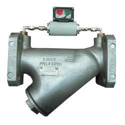
Depending on the degree of filtration, the filters have the following versions:
FGK1 - filter with a filtration degree of 50 microns; FGK2 - a filter with a filtration degree of 250 microns (for technological purposes).
The performance of the filters during operation is governed by pressure loss.
The filter pressure loss indicates the degree of contamination of the filter element.
The maximum pressure loss across the filter at maximum flow does not exceed:
for FGK2 filters with a nominal diameter of 250, 300 -1.2 kPa.
For pressure control, threaded holes (M12x1.5-7H) with plugs are provided, into which, at the request of the customer, couplings for measurements can be installed.
Main technical data of FGK gas filters

An example of a filter designation entry: FGK-A-DN-Rrab.-V TU U 29.2-05782912-010:2011, where:
A - filter version: FGK1; FGK2.
DN - nominal diameter of the filter: 50; 80; 100; 125; 150; 200; 250; 300.
Pwork - the value of the maximum working pressure, MPa, is selected from the range: 0.63; one; 1.6; 2.5.
L - turbine type counter, P - rotary type counter.

![]()
Literature:
1) Staskevich N. L. Reference book on gas supply and use of gas / N. L. Staskevich, G.
N. Severinets,
D.I.Vigdorchik. - L .: Nedra, 1990.
2) SNiP 42-01-2002. Gas distribution systems. - M.: Gosstroy of Russia. State Unitary Enterprise TsPP, 2003.
3) SNiP 2.04.08-87*. Gas supply / Gosstroy of the USSR. - M.: CITP Gosstroy of Russia, 1994.
4) Ionin A. A. Gas supply / A. A. Ionin. - M.: Stroyizdat, 1989.
5) Enin P. M. Gas supply of housing and communal facilities / P. M. Enin, M. B. Semenov, N. I. Takhtamysh. Kyiv: Bud1velnik, 1981.
6) SNiP 23-01-99. Building climatology. - M.: Gosstroy of Russia. State Unitary Enterprise TsPP, 1999.
7) SNiP 2.04.07-86*. Thermal networks / Gosstroy of Russia. - M.: CITP Gosstroy of Russia, 1994.
8) Guskov B. I. Gasification of industrial enterprises / B. I. Guskov, B. G. Kryazhev. -M.: Stroyizdat, 1982.
9) Kazimov, K. G. Fundamentals gas facilities/ K. G. Kyazimov, V. E. Gusev. - M.: Higher school, 2000.
10) SkaftymovH. BUT.