This article is a modeler's story about making a DIY Range Rover 4x4 vehicle from a plastic model. It reveals the nuances of manufacturing axle drives, installing electronics and many other nuances.
So, I decided to make a car model with my own hands!
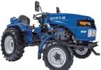
Bought a regular Range Rovera bench model from the store. The price of this model is 1500 rubles, in general it is a little expensive, but the model is worth it! Initially I thought of making a hummer, but this model is much more suitable in design.  I had electronics, well, I took some spare parts from a trophy collector called "cat" which I didn't need for a long time and was disassembled for parts!
Of course, it was possible to take other prefabricated models as a basis, but I wanted just such an off-road jeep.
It all started with bridges and differentials that I made from copper pipes and soldered with an ordinary 100w soldering iron. Differentials are ordinary here, the gear is plastic, the rods and the drive bones are made of iron from the trophy. 
These tubes can be purchased at any hardware store. 
I took the differential gear from a conventional printer. I didn't need him for a long time, and so I decided that it was time for him to retire.  Everything turned out quite reliably, but it is rather inconvenient to work with a soldering iron!

After I made the differentials, I had to close them with something, I closed them with caps from under the pills.  And painted it with ordinary auto enamel. It turned out beautifully, although the trophy drinker hardly needs beauty.
Then it was necessary to make steering rods and put the bridges on the frame, the frame was included and to my surprise it turned out to be iron, not plastic.


It was quite difficult to do this, since the scale of the parts is very small and it was not possible to solder here, I had to screw it with bolts. I took the steering rods from the same old trophy case that I disassembled.

All the parts of the differentials are on bearings. As I have been making the model for a long time.  I also ordered a gearbox with a reduction gear, the gear will be turned on by a microservice from the remote control.

Well, in general, then I installed a plastic bottom, cut out a hole in it, installed a gearbox, cardan shafts, a homemade gearbox, an ordinary collector engine for such a small model, there is no point in setting the bk, and the speed is not important to me. 
The engine is from a helicopter, but in the gearbox it is quite powerful.
 The most important thing is that the model does not go in jerks, but smoothly without delay, the gearbox was not easy to make, but the main thing is ingenuity.
The gearbox was screwed to the bottom, it held up perfectly, but to attach the bottom to the frame I had to tinker.

 Then I installed electronics, shock absorbers, and a battery. At first I put the electronics rather weak and the regulator and the receiver were a single whole, but then I put everything separately and the electronics were more powerful.

.1390645053061.prev.jpg)


And finally, painting, installing all the main units, decals, headlights and more. I painted everything with usual paint for plastic in 4 layers, then painted the wings brown and sanded the parts to give a worn and worn look. 
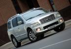
 The body of the model and the color are completely original, the color was found on the Internet and the photo of the real car was done according to the original. This combination of colors exists on a real machine and was painted in this color at the factory.

Well, here are the final photos. I will add a video with the test a little later, and the model turned out to be very passable, the speed was 18 km / h, but I did not make it for speed. In general, I am satisfied with my work, and you will appreciate it.
 The machine is not large, scale 1k24 in size and there is the whole point of the idea, I wanted myself a mini trophy.


The model is not afraid of moisture! He sealed everything himself, he simply covered the electronics with varnish, very reliably, no moisture is terrible.
 Servomachine micro park from the plane to 3.5 kg.


The battery is enough for 25 minutes of riding, but I will put more powerful electronics and a battery, because this is not quite enough.


Even the bumpers are the same as on the original. And the mounts on them are the same. The drive on it is not 50 to 50%, but 60 to 40%.

In general, the Range Rover turned out in a rustic style, I did not even think that it would turn out to paint so high-quality because I don't really know how to paint, although there is nothing difficult! .1390645295252.prev.jpg)

I forgot to add for beauty, I also installed a roll cage and a full-fledged spare tire. The spare wheel and frame were included with the kit.

More about radio-controlled models:
Mishania comments:
Tell me, how is the four-wheel drive arranged, what is inside the bridge except for the transfer case? There must be a steering knuckle after all.
I must say that in the modern market for radio-controlled cars today there is an overabundance, but it is filled with models, as a rule, of Chinese production, although among them you will find a product for almost every taste. However, there are always craftsmen who are not satisfied with the current proposals or they believe that a radio-controlled machine, assembled with their own hands, will always be better than even good conveyor copies. It is for novice craftsmen that our article today is written. Let's start with the tools you need, then describe how to work and give some helpful tips.
How to Assemble a RC Car: Tools
So, we need the following:
- the model of any car, the simplest one can be, any production - even Chinese, even domestic, American or European;
- VAZ solenoids for opening doors, 12-volt battery;
- radio control equipment - AGC (not to be confused with Automatic Gain Control, since the abbreviation is the same);
- batteries with chargers;
- radiator;
- electronic measuring equipment;
- soldering iron and metalwork tools;
- a piece of rubber (needed to strengthen the bumper).
Diagram of a radio-controlled car
Well, now we turn to the scheme, that is, to the process of creating a high-quality model of the RU-machine. First, we assemble the suspension - for this, we need a basic model and a 12 V battery. It will look something like this:
Now we take VAZ solenoids and plastic gears and assemble the gearbox. We cut threads on the studs and the body so that gears and solenoids can be hung. Everything should look something like this:

Now we connect the gearbox to the power supply and check, after which we install the gearbox in the car, if it passed the test. We install a radiator in order to protect the circuit from overheating. The radiator plate, by the way, can be very securely fixed with bolts. After that, we install the power driver and radio control microcircuits. They can be clearly seen in this photo:

Well, then we completely assemble the body of our car. After that, you can proceed to test runs of the car. Now for a few tips.
So you have a radio controlled car, how do you make it maneuverable and reliable? First, do not overload the model with unnecessary details and systems. Sound signals, illuminated headlights, opening doors - all this, of course, is good and beautiful, but creating a radio-controlled car is a rather difficult process, and its further complication can negatively affect the basic "driving" qualities of your model. Therefore, the main thing to focus on is to make a good suspension and ensure reliable signal transmission. Well, fine-tuning the systems during test drives will help you to improve maneuverability and optimize speed characteristics. As for specific schemes, it is simply not possible to describe even the hundredth part of them in this article, so I refer you to
1. Introduction
2. Types of car models
3. Internal combustion engine versus Electro. Comparison.
5. Batteries
6. Fuel
7. Body models
8. List of necessary things
1. Introduction
So, you are interested in radio-controlled car models. Whether it's a model with an internal combustion engine (ICE) or a model with an electric motor, this article will help you determine what you prefer, understand some of the general principles of the model and radio control, and buy everything you need for further operation.
First, let's take a look at the different types of car models.
2. Types of car models
Radio controlled car models can be classified as follows:
- by scale (size): 1:12, 1:10, 1: 8
- by engine type: ICE (or nitro) (internal combustion engine) or Electric (electric motor)
- by chassis type: Road, Formula 1, Buggy, Truck, Monster trucks (or Monsters)
Let's look at everything in order:
Scale
The scale of the model is indicated as for example 1:10 (or 1/10). The most common scales are 1:10 and 1: 8. The 1:12 scale is getting pretty rare. The 1:18 scale is gaining popularity (very popular among conventional, bench car models), new models of both road cars and monsters appear in it.
There are also 1:24 and 1:28 scales in which the Japanese company Kyosho makes the Mini-Z series, but these scales are approximate, they are indicated as an average for the series.
And finally, at the other extreme - 1: 5 scale - these are huge cars (about a meter long) with gasoline engines.
 |  |
ICE (left) and electric motor. The proportions are not met! Usually the electric motor is much smaller than the internal combustion engine.
engine's type
Engines on the models are as follows: Internal combustion engine (ICE, also the term Nitro is used) and Electric motors.
Internal combustion engines (in the picture on the left) run on a mixture of methanol, nitromethane and oil. This fuel is sold in cans at model stores. It is better to use high quality branded fuel to keep the engine running well and lasting a long time. ICEs are divided into classes according to their working volume:
Grade 12 (2.11cc) - 1:10 scale road models
15th grade (2.5cc) - road models 1:10, buggies, trucks, monsters 1:10
18th grade (3.0 cc) - buggies, trucks, monsters 1:10
21st class (3.5cc) - road 1: 8, buggies and monsters 1: 8
25th class (4.1 cc) - buggies and monsters 1: 8
The name of the classes comes from the American classification of volume in cubic inches. So, for example, the 15th class means that the engine volume is 0.15 cubic meters. inch. When converted to cubic centimeters, it turns out: 0.15 * 2.543 = 2.458 cubic meters. cm, i.e. about 2.5.
The higher the class, the larger the engine displacement, the higher the power. For example: the power of the 15th class engines is about 0.6 hp. up to 1.2 HP Engines of the 25th class already develop 2.5 hp. and more.
Electric motors (pictured to the right) are usually powered by 7.2 V or higher batteries. Batteries are soldered from elements of 1.2 V. They also sell separate elements for soldering and ready-made batteries.
Electric motors are classified by the length of the wire wound inside (by the number of turns) - 10 turns, 11 turns, 16 turns, 24 turns, etc. The fewer the number of turns, the faster the engine.
Chassis type
The chassis is the foundation of the model. All important elements are attached to it - engine, electronics, etc. Different chassis types serve different purposes and are designed based on the application.
Formula 1- designed for the development of high speeds and racing on an absolutely flat surface. The drive is rear-wheel drive (2WD), although there are models with all-wheel drive (4WD).
Buggy- for off-road racing (sand, clay, gravel, mud), can jump from trampolines. Drive - full (4WD) or rear (2WD).
Tracks- similar in design to a buggy, but have a higher ground clearance and larger wheels. Drive - full (4WD) or rear (2WD).
Monsters- have huge wheels and are able to overcome any obstacles and ride on any surface. The long suspension travel allows you to jump from high jumps and do whatever you want. Drive - full (4WD) or rear (2WD).
Road models- are able to ride on a flat surface and have high speed and good handling. Drive - full (4WD), less often rear (2WD).
 |  |
 |  |
 |
|
3. Internal combustion engine (internal combustion engine) versus Electro. Comparison
Before making a choice, you need to weigh the pros and cons of each type of engine. A correct understanding of the advantages and disadvantages of models with an electric motor and with an internal combustion engine will help to rationally spend money and avoid problems and disappointments. So:
ICE models
Many ICE models are faster than electric models and can exceed speeds of 70-80 km / h. Be that as it may, hitting a curb or wall at 70 km / h can completely destroy the model or cause costly repairs.
ICEs for car models are single-cylinder two-stroke engines, which means they need fuel (not gasoline, but special fuel). This means that you will have to regularly buy fuel for the model (the approximate price of 4 liters of good fuel is $ 45, however, the canister lasts quite a long time). The advantage of a model with an internal combustion engine is that you can drive it for as long as you like - the main thing is to fill the tank with fuel. As a rule, models with internal combustion engines are more expensive than models with an electric motor (due to the higher cost of the engine itself). Among the significant advantages of models with internal combustion engines is realistic sound.
Models with electric motor
The main disadvantage of electric models is that the battery runs out quickly. You are unlikely to be able to drive continuously for more than 15 minutes on a single charge. But apart from a short ride time and a slightly lower top speed, otherwise the electric models are better. The main advantage of models with an electric motor is their silence, environmental friendliness and much better acceleration compared to models with an internal combustion engine.
Be that as it may, you still have to buy some additional equipment for the model - batteries and a charger. Batteries cost from $ 15 and differ in capacity and current output. The better the batteries, the higher the price, and it increases non-linearly. The chargers work either from 12V (powered by a cigarette lighter or a conventional car battery), or 220V (mains). There are chargers that can work from 12 and from 220V.
4. Radio control (equipment)
No matter what type of chassis and what scale you choose, you need a radio control system for the model. Many companies make models of some of their models in the form of RTR (Ready To Run) - ready to use right out of the box - they are usually already assembled and include everything you need, including a remote control. However, some of the models are still sold as an assembly kit and control equipment will have to be purchased additionally. Let's take a look at the principle of model driving.
Radio control system for a car model with an electric motor:
 |
3. If the driver turns the steering wheel, the Receiver will send a signal to the Servo (also called Servo), forcing it to turn in the right direction. Through the linkage system, this servo turn causes the model wheels to turn.
4. If the rider pulls the trigger, the Receiver sends a signal to the Regulator (Speed Regulator).
5. The speed controller (also called the Stroke controller, Speed controller) changes the speed of the electric motor and, consequently, the speed of the model (the engine is connected to the wheels by a system of belts and / or cardan shafts).
6. The battery is used to power the Motor, Servo 1, Receiver and ESC. If the model has an electronic speed controller, then the battery is connected to it, and the controller distributes power to the motor, receiver and servo.
Radio control system for a car model with an internal combustion engine:
 |
1. When the rider pulls the trigger or turns the steering wheel on the Control Panel, a signal is sent to the Model Receiver.
2. The receiver receives the signal, processes it and sends the signal to the corresponding devices in the model.
3. If the rider turns the steering wheel, the Receiver will send a signal to Servo 1, forcing it to turn in the desired direction. Through the linkage system, this servo turn causes the model wheels to turn.
4. If the rider pulls the trigger, the Receiver sends a signal to Servo 2.
5. Servo 2 moves the carburetor choke, which changes the flow of the fuel / air mixture and therefore the engine RPM and model speed.
6. The battery is used to power the Receiver, Servo 1 and Servo 2.
The items shown above constitute a complete listing of the model's radio equipment. All of these elements are required to drive the model. ESCs are usually sold separately, while the remote control, receiver and servos are sold separately or all in one kit.
5. Batteries
If you decide to buy a model with an electric motor, you will need batteries. Car models usually use 7.2V batteries, which are soldered in 6 1.2V cells. At the moment, there are two types of batteries widely used - Nickel-cadmium (NiCd) and Nickel-metal hydride (NiMH). Each type has its own advantages and disadvantages, but NiMHs allow for a large battery capacity and have little or no memory effect.
How batteries differ.
Batteries are characterized by many parameters - internal resistance, average voltage, discharge current, etc. The exact values of these parameters are given for expensive batteries for serious sports, for hobbies and amateur racing you can not focus on them and buy more affordable batteries. In this case, the most important parameters are the type of battery (NiCd or NiMH) and its capacity (measured in mAh, for example 2400 mAh), it is indicated on the batteries in large numbers. The higher the capacity, the longer you can ride the model. The price, however, also increases ...
How many batteries should I buy?
For a start, it would be good to buy 2-3 batteries, which will allow you to ride with replacement batteries for a long time. As for the capacity, it is better not to buy batteries with a capacity of less than 1500mAh, otherwise the driving time will be very short.
6. Fuel
Internal combustion engines for models cannot run on regular gasoline. They require a special fuel based on methanol and with the addition of varying amounts of nitromethane and oil. Nitromethane improves engine performance, and its content in car fuels is typically 16 to 25%. The oil in the fuel helps lubricate the engine and protect it from damage. Fuel cans usually indicate the nitromethane content and the type of model for which the fuel is applicable.
7. Body models
Bodies for car models are made of special plastic - polycarbonate (Lexan). The bodies are quite light and flexible so as not to break when struck. Models can be sold with or without a body. But you can always buy a body separately - fortunately, a great variety of bodies are available, copying a huge number of real cars.
Bodies are sold already painted or unpainted (transparent). The transparent body is painted from the inside with a special paint for polycarbonate, which can be found in any shop for modelers.
Bodies of different manufacturers may differ in the degree of detail and strength: some bodies are well-designed, accurately copy the original, but at the same time they are quite fragile. Other bodies contain less detail but are more resilient and impact resistant. If you are a beginner, then try to choose more flexible bodies, because accidents are inevitable in the beginning and happen more often than it seems at first glance.
 | + |  | = |  |
8. List of necessary things
And, finally, a complete list of what you should buy for the model for its full functioning, start and maintenance.
For model with electric motor:
- Chassis (with electric motor)
- Radio control (the kit must contain 1 remote control, 1 receiver and 1 servo)
- Speed controller (depends on the motor model, consult your dealer)
- Batteries (buy at least 2 batteries with a capacity of at least 1500mAh)
- Charger
For model with ICE:
- Chassis (with engine)
- Radio control (the kit must contain 1 remote control, 1 receiver and 2 servos)
- Rechargeable batteries or batteries (for powering the receiver and servos, usually 4x AA)
- Body (if it was not included with the chassis)
- Body paint (it is better to buy 2 spray cans)
- Fuel
- A bottle for filling fuel into the model's tank
- Glow plug device (called glowstart in English)
My blog is searched for by the following phrases
The idea of \ u200b \ u200bcreating a radio-controlled car model arose a long time ago. But the implementation of this idea in plastic and metal all the time hindered some objective reasons. Firstly, the complete lack of experience in the design and construction of such a model (my hobby is aircraft modeling, and the structure and operation of some units of car models, the types of materials used, engines, batteries, the selection of a gearbox, etc. I was very vague). Secondly, the complete absence of literature on this topic. Thirdly, the lack of components (motors, gears, small diameter bearings, etc.). Surprisingly, the latter problem was quickly and easily resolved. I work at a data center, and the guys who know about my hobby for modeling somehow gave me some decommissioned printing mechanisms from printers and tape drives. From all these "pieces of iron" I managed to pick up several pairs of gears with different gear ratios, several high-quality steel shafts for axles and small bearings. Literature was also quite simple: I reviewed all the magazines "Modelist-Constructor" in my own library and in my library, and found some interesting articles for me. To begin with, it was decided to build the simplest model (no differential, no depreciation, no bearings, the engine from the car door lock locking mechanism, power supply - 8-10 SC-0.55 A / h batteries).
After closer acquaintance with the catalog and models of the TAMIYA firm, I was convinced that I did not make a model, but a toy. I wanted to build something more serious, I had to develop blueprints again. Due to the rather high complexity of the components of proprietary models (almost all parts are cast and of complex configuration), a transmission containing many parts, low strength and durability of mechanisms (please note that this is my subjective opinion), I do not even design an all-wheel drive and front-wheel drive chassis tried to. The prototype was the chassis from the Formula 1 model; the model was originally conceived for asphalt. Materials - sheet fiberglass, steel, duralumin, caprolactam, microporous rubber. The differential was made according to the description in the "Model-constructor", the front suspension is similar to the proprietary one, but made of fiberglass, the regulator is home-made, mechanical. During operation, some nuances arose that did not suit me. First, the wheels are completely unprotected from the blows of rivals. I had to change the front suspension arms several times and the rear axle axle a couple of times. Secondly, a very dense arrangement of mechanisms under the body of a small volume, and, as a result, difficult maintenance and cleaning of units. Thirdly, the material for the parts of the differential was poorly chosen, and its work did not suit me.

Taking into account the above, as well as the accumulated experience in the creation and operation of such models, a slightly different version of the chassis was developed. The changes mainly affected the type of chassis (for a closed body), the layout of the units, some parts of the differential, the steering gear protection unit. It is rather difficult for me to give an objective assessment of my "work", but the chassis suits me. Compared to the TAMIYA models, the chassis is faster (although the comparison was made visually, the front-wheel drive, all-wheel drive and my chassis were compared; the models were standard, without additional options). Parts and mechanisms are simpler than branded ones, in case of breakage, they can be easily repaired or repaired.

Unfortunately, I did not have the opportunity to work with the branded components (wheels, differential parts, etc.). But I think that by changing the size and configuration of some parts of the front suspension and rear axle, it is quite possible to apply the standard wheels, differential, shock absorbers, etc., produced by firms. In addition, by changing the size of some parts, it is quite possible to change the base and track of the chassis, that is, to make the chassis for any closed body. And, finally, the chassis did not cost me $ 200 plus about the same for tuning (maybe somewhere the prices are lower, but we have such).
In this material, I in no way want to belittle the merits and achievements of manufacturers of model products, offend people who have the opportunity to buy expensive models and accessories for them or pretend to be new ideas. Almost all the materials were published in the "Modelist-Constructor" magazine, however, I sometimes used other materials, changed something and modified it taking into account the details that I had. In general, what I have succeeded is what I bring to your attention.
Brief technical characteristics
| Chassis type | backward |
| Base | 260 mm |
| Rear wheel width | 200 mm |
| Front wheel width | 188 mm |
| Ground clearance | 14 mm |
| Chassis weight | 700 g |
| Transfer type | single stage open gear; K = 1: 4.2 or K = 1: 4.5 |
| engine's type | Mabuchi 540, Speed 600 of various modifications |
| Front suspension | independent, depreciation - fiberglass plate |
| Rear suspension | dependent, depreciation - fiberglass plate and oil shock absorber-damper |
| Batteries | 7.2 Vx1400mA / h plus 4.8Vx260mA / h for on-board equipment |
Description of the structure
Chassis base
Functionally, the chassis consists of three main components: a chassis base, a rear axle with a shock absorption system and a front suspension with a shock absorption system and a protective clutch. The base of the chassis is part 1, cut from 2.5 mm thick fiberglass. On this part, they are installed in the corresponding grooves of the sidewalls 3 and 4, which form a box-case for placing power batteries. After installing these parts, the joints are degreased and spilled with epoxy. On the racks 5 (material-duralumin or aluminum alloy), the "second floor" of the chassis 2 is attached, on which the steering gears, the travel regulator, the attachment points for the oil shock absorber and the steering gear protective clutch are located. It should be noted that the grooves of part 2 must coincide with the corresponding spikes of the sidewalls 3 (these places are not glued!). This assembled design increases the strength of the battery box. Brackets 6 are installed in front of the rear wheels, which play the role of protective "ears" and, in addition, they are equipped with body fastening pins. At the front of the chassis, the body can be attached to similar pins installed in the bumper area. The bumper configuration depends on the prototype bow and is not shown in the drawings. Also, the attachment points of the body pins are not shown. Their location depends on the contours of the prototype hood. Due to the fact that fiberglass is inferior in strength to carbon fiber, the relief windows are cut out only in the parts that form the box for the power battery.
Rear axle with shock absorption system

The rear axle is made as a single, easily removable unit, which increases the convenience of repair and maintenance. The base of the bridge (see section A-A) is a glass fiber laminate plate 3 2.5 mm thick (you can use duralumin 2 mm thick). The motor frame 1 and the left wheel rack 2, made of 6 mm thick duralumin, are attached to it with M3 screws. The upper frame of the rear axle 4 is fastened from above with the same screws. Bearing cups 5 (right) and 6 (left) are attached to the engine frame and the rack. The right one was machined from steel and brought to the dimensions shown in the drawing; the left glass is made of duralumin. Bearings-13x6x3,

closed type. The axle 20, which connects the rear wheels, is made of a steel bar with a diameter of 6 mm. In the place where the left wheel is installed in the axle, an M2.5 hole is made for the pin. In the hub of the left wheel 17, a groove with a width of 2.5 mm is cut through. When installing the wheel on the axle, the pin enters the cut in the hub and thus prevents the wheel from turning on the axle. The right wheel is connected to the driven gear 11 (the drawing on the left shows the gear that I found, on the right it is after revision) through a ball friction clutch. It is formed by 6 balls with a diameter of 4.8 mm from the bearing located in the sockets of the cylindrical insert 10 (the cylindrical insert is connected to the gear with six M1.5 screws; holes for the screws are drilled around a circle with a diameter of 37 mm at 60o; a bronze plain bearing 12 is pressed into the insert) ... On both sides, the coupling is compressed with steel hardened washers 9 (washers size 30x13x1.2). One of the washers is glued into the hub of the right wheel 13, the second is glued to the thrust disk 8. The thrust disk is seated on the axle through a split bronze bushing 7. The thrust ball bearing 15 (made of steel bar; after grooving under the balls of the part are hardened). Adjustment of forces in the coupling is carried out by tightening the nut with a nylon insert 19. To prevent axial displacements, a bushing 21 is installed on the axis 20, which is fixed on the axis with an M3 screw. The right wheel hub 13 and the left disc 16 are machined from caprolactam; two bronze plain bearings 14 are pressed into the right-hand hub. The wheel tires are made of microporous rubber. To eliminate the axial play, a spacer washer 18 is used.
The rear axle is hung on the chassis base through a fiberglass shock absorber plate 22 using three M3 screws. On the base of the chassis, this part is fixed with a screw M4 and a pressure washer 23, which is screwed onto the rod 24. This rod is the axis of the frictional shock-absorbing unit. The latter consists of 25 disc friction washers and springs. The force of the friction clutch is regulated by movement along the axis of the sleeve 27, which is fixed with an M3 screw. The lower support 26, the spring rests on an additional spring bar 28, which is mounted on the struts 29 on the base of the chassis 1.
To dampen vibrations that occur during the operation of the suspension, a damping spring-oil shock absorber is installed. It is attached to part 2 using a duralumin bracket (Node I). The shock absorber is connected to the upper frame of the rear axle 4 by a ball joint (Unit II).
Front suspension

The front suspension was originally simplified (section Г-Г), and consisted of the upper and lower planks 1 made of foil-coated fiberglass, interconnected by struts 2 and attached to the base of the chassis 1 through rubber washers (Unit III). The swing arm consisted of parts 3, 4, 5, assembled into one unit by soldering. Amortization was carried out with the help of a spring and by moving part 3 along axis 6. On the axis 6, grooves were made for locking washers. Two bronze plain bearings 9 were pressed into the wheel disk 8.
But I didn't like the work of such a suspension, and with the help of an article from the "Modelist-Constructor" magazine, another suspension was developed and manufactured (details are shown in the drawing to the right of the red dashed line). The base is node 1, assembled from parts 1A, two parts 1B ( fiberglass) and duralumin parts 2. Parts 1B are glued to 1A, for greater strength tightened with M2 screws; part 2 is screwed in with M2 screws. The lower suspension arm 3 consists of a base 3B and two sidewalls 3A (fiberglass 2 mm thick); after fitting and assembly, the joints are degreased and spilled with epoxy resin. Upper arm 4 consists of shackle 4A, fork 4B and axle 4B. Earring material and

forks - duralumin. The levers are attached to the base 1 using axles 15; in their places, the axles are fixed with locking washers 16. Using the same axis, the pivot rack 5 is attached to the lower lever (a factory-made part, but it is quite possible to make it from duralumin, simplifying it a little). The post 5 is attached to the upper arm 4 with a fork 4B and an M3 screw. The shackle 4A is attached to the unit 1 as shown in view B (the axis of rotation 15 is fixed with lock washers 16, fluoroplastic bushings 14 serve to prevent axial displacement of the shackle). The pivoting arm 6 is a piece of duralumin, a steel axle 7 is inserted into it with some interference, after which a vertical hole with a diameter of 4 mm is drilled under the axis of rotation 8. The axis of rotation is fixed with a lock washer.

Wheel disks 9 are turned from caprolactam. Hubs 10 are made of duralumin, fastened to the discs with three M2.5 screws. Bearings - 13x6x3, enclosed design. Wheel tires are made of microporous rubber.
Amortization is carried out using a plate 11 made of fiberglass, which is pressed against the base 1B by an M3 screw and a duralumin washer 12. The free ends of the plate rest on fluoroplastic bushings 13, which are put on the axle 15. This design allows you to adjust the stiffness of the suspension due to the thickness and width of the plate 11 rather within wide limits.
The steering gear protection sleeve is a unit shown in section B-B. Compared to the node published in the "Modeler-Constructor", it has been slightly redesigned. The base is a steel axle 1, on which a piece of bronze 3 is fitted into an interference fit. After that, a hole with a diameter of 1.5-2 mm is drilled in these parts together, a pin is inserted and sealed. Thus, part 1 and 3 are tightly connected. The rocker 4 is soldered to part 2, and the assembly is assembled as shown in the drawing. Axle 1 rotates in a needle bearing, which is installed in part 6 (which, in turn, is installed in the hole in the base 1). The second bearing is a nylon bushing 5 installed in part 2. The depth of the hole with a diameter of 5.2 mm on part 5 must be selected so as to ensure the minimum backlash of the axle 1 of the protective clutch, but at the same time the ease of rotation of the unit. The clutch is set in rotation using a duralumin rocker 7.
Conclusion
A few words about the model itself. The Ferrari F40 served as a prototype, so the base and width of the chassis, the diameter of the wheels were developed based on the actual dimensions of the car, on a scale of 1:10. The body is made of fiberglass, glued on a dummy. Control equipment - Graupner FM-314, steering gears - standard 508 (similar in size to HS 422 Hitec).
I tried to describe in as much detail as possible the course of my thoughts during the development and the procedure for manufacturing the chassis. It is possible that some of the nodes could have been made differently, using different materials or design solutions. I want to give a little advice to those who want to repeat this model. First, you need to select the components (gears, shock absorber, swing arms, etc .; it is quite possible that you will not be able to pick up parts according to the dimensions indicated on the drawings) and materials for homemade parts. After that, you may have to make some adjustments to the drawings, and only then start manufacturing. If anyone has any questions, suggestions, criticism, I will be glad to talk on the forum.

Buying a radio-controlled device today is not a problem. And a car, and a train, and a helicopter, and a quadcopter. But it is much more interesting to try to create a radio-controlled car with your own hands. We will present you with two detailed instructions.
Model # 1: what do we need?
To create this radio-controlled model you will need:
- A model car (you can even take an ordinary Chinese one from the market).
- AGC auto.
- Solenoid for opening the doors of a VAZ car, battery 2400 A / h, 12 V.
- A piece of rubber.
- Radiator.
- Electrical measuring instruments.
- Soldering iron, solder to it, as well as locksmith tools.
- Reducer.
- Brush motor (for example, from a toy helicopter).
Model number 1: instructions for creating
And now we start creating a radio-controlled car with our own hands:
Model # 2: required accessories
To create a car you will need:
- Automobile model.
- Spare parts from an unnecessary collection machine, printer (gears, rods, iron drives).
- Copper tubes (sold at hardware stores).
- Soldering iron.
- Auto enamel.
- Bolts.
- Necessary electronics.
- Battery.
Model # 2: creating a device
Let's start making a radio-controlled car with our own hands:

In conclusion, we will present you one of the drawings for radio-controlled models of cars - a receiver diagram.

A homemade radio-controlled car is a reality. Of course, you won't be able to make it from scratch - develop your experience on simpler models.