In order to prevent blocking of the wheel of the car and, as a result, driving on the road, the anti-lock system is used in Toyota Corolla. The appointment of a fully automated anti-lock system is to maintain controllability in the event of emergency braking machine, the exclusion of its uncontrolled slippage.
Fig. 1. Trajectory braking when braking
Anti-blocking is valid for the following principles:
- in the initial torque, special sensors on wheels fix the initial impulse of the lock;
- by feedback on the electrical wire, a signal is formed that controls the weakening of the hydraulic cylinders effort before the start of the slippage, the tires are again included in the clutch with the road;
- after scrolling the wheel, the maximum brake force in the hydraulic cylinders is again created;
Due to the multiple repeatability of this simple electro-hydromechanical chain, the braking path is practically no longer large than with continuous blocking, but the handling is fully saved. This avoids the drift, the car's removal on the oncoming traffic lane or on the roadside.
Device of the abs
The main nodes of the anti-lock system:
- high-speed front and rear sensors;
- hydraulic brake hydraulic valves;
- sensor information exchange channel elements with hydraulic system valves.
Braking with anti-lock is especially important for drivers who do not have greater experience, as it is enough to keep the brake pedal "to the floor", and everything else does the system. But here in the areas of the road with a loose coating in the form of gravel bearing, sand or snow, the deceleration path turns out to be greater than when braking through the complete and continuous blocking of the brakes. After all, the tires do not break into the loose mass, and slip through its surface.

Fig. 2. Installation sites ABS assemblies in the car
In fig. 2 shows the location of the main nodes of the automotive system in the overall structure of the car.
The arrows indicate the following elements:
- Anti-lock complex drive;
- Control relay;
- Control unit and photodiode on the activation of the anti-lock system;
- Speed \u200b\u200bwheel sensor;
- Rotor speed sensor in the front wheel;
- Speed \u200b\u200bsensor rotor in the rear wheel;
- Speed \u200b\u200bsensor on the rear wheel.
The effect of the anti-lock complex is reduced to preserving the stability and controllability of the machine with optimal reduction in the speed of movement. All this is due to tracking the speed of rotation of each wheel and periodic discharge of pressure in its brake hydraulic highway.
Electronic Module ABS
The anti-lock control unit is located next to the dashboard. It includes and handled electrical pulses from wheel speed sensors. After processing information, the node gives signals to the anti-lock drive drive valve.
Also, with the help of an electronic module, the performance of the entire complex is constantly monitored and tested. In the event of malfunctions on the dashboard, the light signal flashes, a warning driver about an emergency situation. Also, the electronics unit is able to generate a malfunction code and store it for a hundred specialist.
Socializing the photodiode signal warns the driver that there are deviations in the operating parameters. In this case, it is necessary to check the reliability of the wire connections from the sensors to the electronic unit, the fuses, filling the main brake cylinder the brake fluid.
If after this warning signals continue to appear, then you should contact a specialized center for repair and maintenance of Toyota Corolla.
Anti-lock car system Toyota Corolla
The device includes a hydraulic pump and a multi-band housing with four magnetic valves. In the cavity of the drive of each wheel is created and adjustable using its valve the desired pressure. The opening and closing signals of the stripe valves come from the wheels rotation sensors.

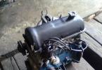
Photo 1. Block ABS Toyota Corolla Fielder
The block can be seen under the hood of the engine compartment. It is located next to the brake cylinder and is connected to it with metal tubes for the brake fluid flow.
High-speed wheel sensors
These elements are installed on the fists of the front wheels. They are located close to the toothed rotors of the external connections of the semi-axes and pinned on the brake panels of the wheels with rotors on the hubs of the wheels, constantly send information as an electrical pulse to the electronic ABS module.

Fig. 3. Sensor speed of rotation of the front wheel Toyota Corolla
Anti-lock system response signals
The driver learns about the operation of the system on a specific twitching of the brake pedal at the time of braking and on a flashing light bulb on the instrument panel. If the light begins to burn continuously, this means a malfunction in the anti-lock complex. However, it is not necessary to beat the alarm - because with faults in the ABS, the braking system works like in all cars without anti-lock.
To disable the anti-lock complex in some models, Toyota Corolla is quite enough to press the brake pedal as during intermittent braking. In the same way, the new inclusion of the complex is also performed.
ABS failure diagnostics
ABS control lamp connection circuitThe driver's ABS failures notify a special test lamp located on the instrument shield of the car. As soon as the ABS control module detects the fact of violations in the system, it produces its disconnection. The brake system continues to function as usual.
The ABS status diagnostics is performed each time when the engine is started and is accompanied by a short-term triggering of the control lamp. For a short time after launching Lama should automatically turn off.
If the ABS control lamp lights up and continues to burn while driving, first make sure that the parking brake is completely released, and the braking system operates properly. If everything is normal, therefore, ABS fails. First, make the following simple checks:
a) Check the condition of brake calipers and wheeled cylinders;
b) Check the condition and reliability of fastening the contact connectors of the ABS control module and wheel sensors (see chapter Side electrical equipment);
c) Check the appropriate fuses (see chapter Side electrical equipment).
ABS control lamp failures
The reason for the failure of the ABS control lamp function may be a break or short circuit in the circuit of its electrical wiring.
The ABS control lamp is not activated when the ignition is turned on
Try to turn on the ignition without making the engine start, if other, included in the device combination, the control lamps work properly, go to the next check step, otherwise you should produce the required dashboard remediation.
Turn off the ignition. Remove the instrument combination, remove the ABS control lamp and check its condition. If the lamp burned, make it a replacement, otherwise go to the next check step.
Discover the contact pair of B62 / F45 and measure the voltage between the chassis (-) and terminal No. G6 (+) B62 connector. If the measurement result is less than 3 V, go to the next check step, otherwise, check the state of the electrical wiring of the corresponding control lamp. Make the necessary recovery repair.
Turn off the ignition, set the test warning lamp to your regular place and set the instrument combination.
Turn on the ignition and repeat the voltage measurement. If the measurement result does not go beyond the range of 10 ÷ 15 V, go to the next check step, otherwise check the wiring condition. Make the necessary recovery repair.
Turn off the ignition and check the voltage between the terminal G6 (+) F45 connector and the chassis mass. If the measurement result is less than 3 V, go to the next check step, otherwise check the state of the corresponding wiring. Make the necessary recovery repair.
Turn on the ignition and repeat the check. If the measurement result is less than 3 V, go to the next check step, otherwise, check the state of the electrical wiring of the corresponding control lamp. Make the necessary recovery repair.
Measure the resistance between terminal No. 23 F49 connector and mass. If the measurement result is less than 5 ohms, go to the next check step, otherwise check the health of the control / hydrojulator assembly assembly. Make the necessary recovery repair.
Measure the resistance between the mass and terminal G6 connector F45. If the measurement result is less than 5 ohms, go to the next check step, otherwise check the status of the connector and the harness of its electrical wiring. Make the necessary recovery repair, if necessary, replace the connector.
Turn off the ignition and check the correctness of the status of the contact connectors on the chain area between the instrument combination and the ABS control module, if there are no signs of the contact reliability, replace the ABS control module assembly.
The ABS warning lamp is not turned off after the engine start
Turn off the ignition and make sure that the contact connector of the control module / Hydromodulator ABS is complete and secured.
Measure the resistance between the mass of the chassis and each (A and B) from the diagnostic terminals (B81). If the measurement result is less than 5 ohms, go to the next check step, otherwise check the state of the harness of the corresponding wiring, make the necessary recovery repair.
Turn off the ignition and connect the diagnostic terminal to terminal No. 8 of the B82 diagnostic connector. Disconnect the ABS control module pin connector and measure the resistance between the F49 connector terminal and the chassis mass. If the measurement result is less than 5 ohms, go to the next check step, otherwise check the wiring status on the chain area between the ABS control module and the diagnostic connector, make the necessary restoration repair.
Run the engine at idle and check the voltage between the terminal in (+) on the rear side of the generator (power terminal) and the chassis mass. If the measurement result does not go beyond the range of 10 ÷ 15 V, go to the next check step, otherwise replace / repaired the generator (see chapter) and repeat the scan.
Turn off the ignition and check the condition of the Pole terminals of the battery and the reliability of the terminal tips on them. If necessary, make the necessary corrections.
Disconnect the ABS control module electrical wiring connector, then run the engine at idle and measure the voltage between the F49 connector and the chassis slot. If the measurement result does not go beyond the range of 10 ÷ 15 V, go to the next check step, otherwise check the power of the power supply circuit. Make the necessary recovery repair.
Dispature the contact pair of B62 / F45 and turn on the ignition - if the ABS control lamp does not work, go to the next check step, otherwise check the condition of the front wiring harness.
Turn off the ignition and check the status of the protrusions of the control module connector. If the terminals are in order, go to the next check step, otherwise replace the control module / hydraulicodulator (see section).
Measure the resistance between terminals No. 22 and 23 of the ABS control module connector. If the measurement result is more than 1 mΩ, go to the next check step, otherwise replace the ABS control / hydrojulator assembly (see section. Removing, installing and checking the functioning of the control of the control module / hydrojulator ABS).
Measure the resistance between the F45 slot G6 terminal and the chassis mass. If the measurement result is less than 0.5 ohms, go to the next check step, otherwise, make the required wire repair.
Connect the electrical wiring to the ABS control module and measure the resistance between the F45 Connector G6 and the chassis mass. If the measurement result is more than 1 mΩ, go to the next check step, otherwise, make the necessary recovery repair of electrical wiring.
Check the status and reliability of the ABS Control Connector Contact Connector. If necessary, make the necessary corrections, or replace the control unit / hydraulic module unit.
Could not read the fault codes
If the test lamp turns on and turns off properly, but does not highlight the initial code (DTC 11, see below) when switching to the diagnostic mode, turn off the ignition and check.
Wheel sensor failures
Wheel sensor failures lead to a malfunction of the operation of ABS. Connection diagram of wheel sensors is presented in illustration.
Open in the chain of the wheel sensor, or an excessively high level of input voltage (DTC Nos. 21, 23, 25 and 27)
Disconnect the wiring from the ABS control module and measure the voltage between the terminal number 1 of the corresponding wheel sensor and the chassis mass. If the measurement result is less than 1 B, proceed to the next check step, otherwise replace the sensor.
Turn on the ignition and repeat the previous check. If the measurement result is less than 1 B, proceed to the next check step, otherwise replace the sensor.
Turn off the ignition and connect the wiring to the sensor. Measure the resistance between terminals No. 11 and 12 (DTC 21) / 9 and 10 (DTC 23) / 14 and 15 (DTC 25) / 7 and 8 (DTC 27) F49 connector. If the measurement result does not go beyond the range of 1 ÷ 1.5 kΩ, go to the next check step, otherwise check the wiring status on the site between the control module and the sensor. Make the necessary recovery repair.
Measure the voltage between mass and terminal No. 11 (DTC 21) / 9 (DTC 23) / 14 (DTC 25) / 7 (DTC 27) of the F49 connector. If the measurement result is more than 1 B, eliminate the cause of the short circuit on the circuit area between the sensor and the ABS control module. In the absence of voltage (less than 1 V), turn on the ignition and repeat the check. If the voltage is still missing (it is less than 1 c), go to the next check step, otherwise check the wiring status between the sensor and the ABS control module, if necessary, eliminate the cause of the short circuit.
Measure the size of the gap between the sensor and the rotor throughout the perimeter of the latter. With insufficient gap (see Specifications) Make it adjust it by selecting the adjustment gasket (26755AA000). If the clearance is too large, remove the remote gaskets and replace the rotor (assembled with the hinge assembly) or the sensor failed. Having finished adjustment, go to the next check step.
Turn off the ignition and measure the resistance between the terminal No. 1 of the contact connector of the wheel sensor and the mass of the chassis. If the measurement result is more than 1 mΩ, proceed to the next check step, otherwise replace the sensor.
Turn off the ignition and connect the wiring to the wheel sensor. Measure the resistance between the chassis mass and terminal No. 11 (DLC 21) / 9 (DLC 23) / 14 (DLC 25) / 7 (DLC 27) of the F49 connector. If the measurement result is more than 1 mΩ, go to the next check step, otherwise check the wiring status on the chain area between the sensor and the ABS control module. Make the necessary recovery repair. If the wiring is in order, replace the control of the control / hydrojulator module.
Restore the original connection of all contact connectors, clean the processor memory (see below) and repeat the reading procedure of diagnostic codes. If no changes (in the direction of improvement) did not occur, replace the ABS control module assembly / Hydromodulator. When new codes appear, go to the appropriate check. If the failure never happened, therefore, the malfunction was temporary, - once again make sure the reliability of fixing all contact compounds.
Short circuit in the chain of the wheel sensor (DTC Nos. 22, 24, 26 and 28)
Turn off the ignition and check the reliability of the sensor fastening bolts (32 nm). If necessary, pull the fastener and go to the next check step.
In the absence of an opportunity to use the oscilloscope, proceed to check the mechanical state of the rotor and cleaning components.
In the presence of an oscilloscope, subdominate the car and install it on the backups - the wheels must completely break away from the ground. Turn off the ignition and connect the oscilloscope between the terminals No. C5 (+) and B5 (-) (DTC 22) / C6 (+) and B6 (-) (DTC 24) connector B62 or 1 (+) and 2 (-) (DTC 26) / 4 (+) and 5 (-) (DTC 28) F55 connector.
Turn on the ignition and rotating the appropriate wheel of the car, follow the oscilloscope testimony. The amplitude of the sinusoidal signal displayed on the screen should not go beyond the range of 0.12 ÷ 1.00 V, - if this condition is not performed, or the signal has an incorrect form, go to the next check step.
Check the wheel of the wheel hub. If the measurement result is less than 0.05 mm, go to the next check step, otherwise replace the hub.
Turn off the ignition. Disconnect the wiring from the appropriate wheel sensor. Measure the resistance between the terminals number 1 and 2 of the sensor connector. If the measurement result does not go beyond the range of 1 ÷ 1.5 com, proceed to the next check step, otherwise replace the sensor.
Measure the resistance between mass and terminal No. 1 of the contact connector of the wheel sensor. If the measurement result is more than 1 mΩ, proceed to the next check step, otherwise replace the sensor.
Connect the wiring to the wheel sensor and disconnect it from the ABS control module. Measure the resistance between terminals No. 11 and 12 (DTC 22) / 9 and 10 (DTC 24) / 14 and 15 (DTC 26) / 7 and 8 (DTC 28) of the ABS control module F49 connector. If the measurement result does not go beyond the range of 1 ÷ 1.5 kΩ, go to the next check step, otherwise, make the necessary wire repair on the circuit area between the sensor and the ABS Hydromodulator Module.
Measure the resistance between the chassis mass and terminal No. 11 (DTC 22) / 9 (DTC 24) / 14 (DTC 26) / 7 (DTC 28) of the Control Module F49 connector. If the measurement result is more than 1 mΩ, go to the next check step, otherwise, check the wiring between the sensor and the module for the presence of a short circuit. Make the necessary recovery repair.
Measure the resistance between mass and terminal No. 23 of the F49 connector. If the measurement result is less than 0.5 ohms, go to the next check step, otherwise eliminate the cause of the grounding quality.
Check the reliability of the attachment of the contact connections of the ABS control module and the wheel sensor. Make the necessary corrections. If contacts are in order, go to the next check step.
Make sure that the car telephone / transmitter of the remote control is mounted on a sufficient distance from the wiring wiring harness.
Restore the original connection of all contact connectors and measure the resistance between mass and terminal No. A5 (DTC 22) / A6 (DTC 24) B62 connector. If the measurement result is less than 0.5 ohms, go to the next check step, otherwise replace the shielded harness.
Restore the original connection of all contact connectors and repeat the reading procedure of diagnostic codes. If no changes (in the direction of improvement) did not occur, replace the ABS control module assembly / Hydromodulator. When new codes appear, go to the appropriate test. If the failure never happened, therefore, the malfunction was temporary, - once again make sure the reliability of fixing all contact compounds.
There are problems associated with the serviceability of the wheel sensor (one or all four) of the information signal (DTC 29)
Evaluate the status of the protector and pumping tires. If necessary, make appropriate fixes / replacements.
Check the reliability of the ABS sensor fastening bolts (32 nm). If necessary, pull the fastener and go to the next check step.
Measure the size of the gap between the sensor and the rotor throughout the perimeter of the latter. With an insufficient gap (see Specifications), make it adjustment by selecting the adjustment gasket (26755AA000). If the clearance is too large, remove the remote gaskets and replace the rotor (assembled with the hinge assembly) or the sensor failed. Having finished adjustment, go to the next check step.
In the absence of an opportunity to use the oscilloscope, proceed to check the mechanical state of the rotor and cleaning components. In the presence of an oscilloscope, subdominate the car and install it on the backups - the wheels must completely break away from the ground. Turn off the ignition and connect the oscilloscope between the terminals No. C5 (+) and B5 (-) (DTC 22) / C6 (+) and B6 (-) (DTC 24) connector B62 or 1 (+) and 2 (-) (DTC 26) / 4 (+) and 5 (-) (DTC 28) F55 connector.
Turn on the ignition and rotating the appropriate wheel of the car, follow the oscilloscope testimony. The amplitude of the sinusoidal signal displayed should not go beyond the range of 0.12 ÷ 1.00 V, - if this condition is not executed, or the signal has an incorrect form, go to the next check step, otherwise go to the following check.
Carefully inspect the wheel sensor and its rotor for signs of damage and contamination. Wipe the components, eliminate the problem.
Check the wheel of the wheel hub. If the measurement result is less than 0.05 mm, go to the next check step, otherwise replace the hub.
Turn off the ignition. Restore the initial connection of the wiring. Clean the processor memory (see below) and repeat the reading procedure of diagnostic codes. If no changes (in the direction of improvement) did not occur, replace the ABS control module assembly / Hydromodulator. When new codes appear, go to the appropriate test. If the failure never happened, therefore, the malfunction was temporary, - once again check the reliability of fixing all contact compounds.
Refusals of the control module / ABS hydrojulator
Violation of the functioning of the intake (DTC 31, 33, 35 and 37) / graduation (DTC 32, 34, 36 and 38) of the solenoid valve
Disconnect the wiring from the ABS control module.
Run the engine to idle and measure the voltage between the F49 control unit and the chassis block. If the measurement result does not go beyond the range of 10 ÷ 15 V, go to the next check step, otherwise check the wiring status between the battery, the ignition switch and the ABS control module. Make the necessary recovery repair.
Turn off the ignition and measure the resistance between the chassis mass and terminal No. 23 of the F49 connector. If the measurement result is less than 0.5 ohms, go to the next check step, otherwise eliminate the cause of the grounding quality.
Violation of the functioning of the ABS management module (DTC 41)
Turn off the ignition. Disconnect the electrical wiring from the ABS control module and measure the resistance between the F49 connector terminal number 23 and the chassis mass. If the measurement result is less than 0.5 ohms, go to the next check step, otherwise eliminate the cause of the grounding quality.
Check out the condition of the state and the reliability of fixing the electrical wiring connectors on the ABS control module, generator and battery. If necessary, make the appropriate recovery. If there are no contact quality violations, go to the next check step.
Make sure the remote control phone / transmitter is installed on sufficient removal from the ABS wiring harnesses.
Turn off the ignition. Restore the initial connection of the wiring. Clean the processor memory and repeat the reading procedure of diagnostic codes. If no changes (in the direction of improvement) did not occur, replace the ABS control module assembly / Hydromodulator. When new codes appear, go to the appropriate test. If the failure never happened, therefore, the malfunction was temporary, - once again make sure the reliability of fixing all contact compounds.
Deviation from the nominal supply voltage level (DTC 42)
Run the engine and warm it up to normal operating temperature. Check that idle speed is correct. Measure the voltage between the terminal in the (+) on the back of the generator and the mass of the chassis. If the measurement result does not go beyond the range of 10 ÷ 17 V, go to the next check step, otherwise check the state of the charge system (see chapter Electrical engine equipment
), make the necessary corrections.
Turn off the ignition and check the condition of the pole terminals of the battery and the reliability of fixing the terminal tips on them. If necessary, clean the contact surfaces of the terminals / tips. If the terminals are in order, disconnect the electrical wiring from the ABS control module, start the engine to idle and measure the voltage between the mass and terminal No. 1 (+) of the F49 connector. If the measurement result does not go beyond the range of 10 ÷ 17 V, go to the next check step, otherwise check the wiring status between the ignition switch and the ABS control module contact connector. Make the necessary recovery repair.
Turn off the ignition and measure the resistance between the F49 terminal number 23 and the chassis mass. If the measurement result is less than 0.5 ohms, go to the next check step, otherwise eliminate the cause of the grounding quality.
Check the condition of the status and reliability of fixing the electrical wiring connectors on the ABS control module, generator and battery. If necessary, make the appropriate recovery. If there are no contact quality violations, go to the next check step.
Turn off the ignition. Restore the initial connection of the wiring. Clean the processor memory and repeat the reading procedure of diagnostic codes. If no changes (in the direction of improvement) did not occur, replace the ABS control module assembly / Hydromodulator. When new codes appear, go to the appropriate test. If the failure never happened, therefore, the malfunction was temporary, - once again make sure the reliability of fixing all contact compounds.
Violation of the functioning of the AT control system (DTC 44)
Turn off the ignition and disconnect the two transmission control module electrical wiring connections (TCM). Also disconnect the wiring from the ABS control module. Measure the resistance between terminal No. 3 F49 connector and chassis mass. If the measurement result is more than 1 mΩ, go to the next check step, otherwise, make the electrical wiring repair on the TCM site and the ABS control module.
Turn on the ignition and measure the voltage between the mass and terminal number 3 of the F49 connector. If the measurement result is less than 1 V, go to the next check step, otherwise, make the required wire repair on the site between the TCM and the ABS control module.
Measure the voltage between mass and terminals No. 3 and 31 of the F49 connector. If the measurement result does not go beyond the range of 10 ÷ 15 V, go to the next check step, otherwise check the wiring status on the site between the ABS and TCM control module. Make the necessary recovery repair.
Check the condition and reliability of fixing the contact connectors of the ABS and AT control modules. If necessary, clean the terminals and go to the next stage of verification.
Turn off the ignition. Restore the initial connection of the wiring. Clean the processor memory and repeat the reading procedure of diagnostic codes. If no changes (in the direction of improvement) did not occur, replace the ABS control module assembly / Hydromodulator. When new codes appear, go to the appropriate test. If the failure never happened, therefore, the malfunction was temporary, - once again make sure the reliability of fixing all contact compounds.
Violation of the functioning of the valve relay (DTC 51)
Turn off the ignition and disconnect the wiring from the ABS control unit. Run the engine at idle and measure the voltage between the terminals No. 1 and 24 of the ABS control module and the chassis module. If the measurement result does not go beyond the range of 10 ÷ 15 V, go to the next check step, otherwise check the wiring status between the ABS control unit and the battery. Make the necessary recovery repair.
Measure the resistance between terminals No. 23 (+) and 24 (-) connector of the control module. If the measurement result is more than 1 mΩ, go to the next check step, otherwise replace the control unit.
Check out the condition of the state and the reliability of fixing the electrical wiring connectors on the ABS control module, generator and battery. If necessary, make the appropriate recovery. If there is no violation of the quality of contacts, go to the next check step.
Turn off the ignition. Restore the initial connection of the wiring. Clean the processor memory and repeat the reading procedure of diagnostic codes. If no changes (in the direction of improvement) did not occur, replace the ABS control module assembly / Hydromodulator. When new codes appear, go to the appropriate test. If the failure never happened, therefore, the malfunction was temporary, - once again make sure the reliability of fixing all contact compounds.
Violation of the function of functioning of the drive electro-vehicle / its relay (DTC 52)
Turn off the ignition. Disconnect the electrical wiring from the ABS control module, then turn the ignition key to the ON position and measure the voltage between the control and chassis module and the chassis terminal. If the measurement result does not go beyond the range of 10 ÷ 15 V, go to the next check step, otherwise, make the electrical wiring repair on the site between the battery and the control / hydraulic module module. Check the SBF-holder of the fuse.
Turn off the ignition and measure the resistance between mass and terminal No. 26 of the F49 connector. If the measurement result is less than 0.5 ohms, proceed to the next check step, otherwise, make a refurbishment of the control circuit of the control unit.
Run the engine at idle and measure the voltage between the F49 connector terminal number 1 and the chassis mass. If the measurement result does not go beyond the range of 10 ÷ 15 V, go to the next check step, otherwise check the wiring status on the sections between the battery, the ignition switch and the ABS control module. Make the necessary recovery repair.
Turn off the ignition and measure the resistance between the mass and terminal number 23 of the F49 connector. If the measurement result is less than 0.5 ohms, go to the next check step, otherwise eliminate the cause of the grounding quality.
During the verification of the sequence of triggering valves of the hydromodulator (see section ABS Hydromodulator Valve Speed \u200b\u200bChecking) For hearing, check the operation of the electric motor. If the motor rotates properly, go to the next check step, otherwise replace the ABS control unit / block assembly.
Check the condition of the status and reliability of fixing the electrical wiring connectors on the assembly of the ABS control module / hydrojulator, the generator and the battery. If necessary, make the appropriate recovery. If there are no contact quality violations, go to the next check step.
Turn off the ignition. Restore the initial connection of the wiring. Clean the processor memory and repeat the reading procedure of diagnostic codes. If no changes (in the direction of improvement) did not occur, replace the ABS control module assembly / Hydromodulator. When new codes appear, go to the appropriate test. If the failure never happened, therefore, the malfunction was temporary, - once again make sure the reliability of fixing all contact compounds.
Violation of the functioning of the stop signals switching switch (DTC 54)
Failure of the stop signal switch leads to a malfunction of the operation of ABS.
Check out the serviceability of stop signals when squeezing the foot brake pedal. If everything is in order, go to the next check step, otherwise check the status of the lamps and electrical wiring chains of the stop signals.
Turn off the ignition. Disconnect the wiring from the ABS control module. Sick the foot brake pedal and measure the voltage between the ABS control module Module F49 and the chassis module. If the measurement result does not go beyond the range of 10 ÷ 15 V, go to the next check step, otherwise check the wiring status on the site between the stop signals sensor and the ABS control module. Make the necessary recovery repair.
Check the condition and reliability of fixing the contact switch connector and the control unit. If necessary, make appropriate corrections. If contacts are in order, go to the next check step.
Violation of the health of the output signal of the G-sensor (DTC 56)
Check the ABS control module assembly assembly: the code is applied to the block surface between the hydraulic lines connecting fittings and for models (see specifications). If the marking meets the configuration of your car, go to the next check step, otherwise replace the ABS control / hydrojulator assembly.
|
Turn off the ignition. Remove the central console (see chapter Body). Bring the G-sensor without disconnecting the wiring from it. Turn the ignition key to the ON position and measure the voltage between the terminals No. 1 (+) and 3 (-) from the outside of the sensor R70 contact connector. If the measurement result does not go beyond the range of 4.75 ÷ 5.25 V, go to the next check step, otherwise check the wiring status on the site between the sensor and the ABS control module. Make the necessary recovery repair. |
Turn off the ignition. Disconnect the wiring from the ABS management module and measure the resistance between the terminals No. 6 and 28 of the F49 control module. If the measurement result does not go beyond the range of 4.3 ÷ 4.9 com, go to the next check step, otherwise, make the required wire repair on the site between the sensor and the ABS dipal module.
Disconnect the wiring from the G-sensor. Measure the resistance between the F49 connector terminal number 6 and the chassis mass. If the measurement result is more than 1 mΩ, go to the next check step, otherwise, make the required wire repair repair on the site between the sensor and the ABS control module.
Measure the voltage between the F49 terminal number 6 and the chassis mass. If the measurement result is less than 1 B, proceed to the next check step, otherwise, make the required wire repair on the site between the sensor and the ABS control module.
Repeat the last check when the ignition is on. If the measurement result is less than 1 B, go to the next check step, otherwise, make the necessary wire repair repair on the site between the sensor and the ABS module.
Measure the resistance between mass and terminal No. 28 of the F49 connector. If the measurement result is more than 1 mΩ, go to the next check step, otherwise, make the required wire repair repair on the site between the sensor and the ABS control module. If the wiring is in order, replace the assembly of the control module / hydraulic modulator.
Turn off the ignition and without disconnecting the wiring, damp the G-sensor. Check the reliability of fixing the contact slots of the sensor and the ABS control module. Turn on the ignition and measure the voltage between the terminals No. 2 (+) and No. 3 (-) of the sensor R70 connector. If the measurement result does not go beyond the range of 2.1 ÷ 2.4 V, go to the next check step, otherwise replace the sensor.
Tilt the sensor at an angle of 90 ° forward and repeat the verification described above. If the measurement result does not go beyond the range of 3.7 ÷ 4.1 B, go to the next check step, otherwise replace the sensor.
Tilt the sensor at an angle of 90 ° and still repeat the check. If the measurement result does not go beyond the range of 0.5 ÷ 0.9 V, go to the next check step, otherwise replace the sensor.
Turn off the ignition. Check the condition and reliability of fixing the contact connectors of the G-sensor and the ABS module. If necessary, make the appropriate recovery. If the contact connections are in order, go to the next check step.
Restore the initial connection of the wiring. Clean the processor memory and repeat the reading procedure of diagnostic codes. If no changes (in the direction of improvement) did not occur, replace the ABS control module assembly / Hydromodulator. When new codes appear, go to the appropriate test. If the failure never happened, therefore, the malfunction was temporary, - once again make sure the reliability of fixing all contact compounds.
Checking the ABS Management Module I / Input Signals
The location map of the contact terminals in the control / hydrojulator module connector and the electrical connections of the ABS components are shown in the illustrations.
ABS electrical connections diagram
1 - Management Module Assembly / ABS Hydromodulator |
13 - exhaust electromagnetic valve of the right rear wheel |
Contact terminal location map in ABS Management Module Connector
The shape of the signal removed from the individual terminals of the ABS sensors is shown on the SPR. illustration. The list of signals is given in the table.
Reading fault codes (DTC) ABS
The list of DTC ABS codes is given in Specifications On this chapter.
Reading DTC codes using SSM
Prepare SSM reader to work.
Connect to SSM diagnostic cable and fill the cartridge.
Connect the SSM diagnostic cable to the DLC connector located on the left under the car instrument panel.
Turn the ignition key to the ON position (Do not start the engine) and turn on the SSM power.
In the main menu ("Main Menu") of the reader screen, select Section (Each System Check) and press the YES key.
In the System Selection Menu field, select the screen (Brake Control System), confirm the selection by clicking on the YES key.
After displaying information about the ABS type, again, press the YES key.
In the "ABS Diagnosis" field, select (Diagnostic Code (s) Display) and confirm the selection by pressing the YES key.
In the Diagnostic Code (s) section of the screen, select (Current Diagnostic Code (S)) (Current Code) or (History Diagnostic Code (s)), press the YES key.
Read current data
Enter the Menu subsection (Brake Control System), wait for the ABS Type message to the screen and press the YES key.
In the "Brake Control Diagnosis" field, select the (Current Data Display & Save) and confirm the selection by clicking on the YES key.
In the Data Select Menu field, select (Data Display) and click Yes.
Using the scroll buttons, moving on the displayed list, select the data you are interested in. The list of output data is given in the table below.
|
Monitor screen |
Type of data output |
Units |
|
The speed corresponding to the speed of rotation of the right front wheel |
Data issued by the right front wheel sensor |
km / h or mile / h |
|
Speed \u200b\u200bcorresponding to the frequency of rotation of the left front wheel |
Data issued by the left front wheel sensor |
km / h or mile / h |
|
Speed \u200b\u200bcorresponding to the speed of rotation of the right rear wheel |
Data issued by the right rear wheel sensor |
km / h or mile / h |
|
The speed corresponding to the speed of the left rear wheel |
Data issued by the left rear wheel sensor |
km / h or mile / h |
|
Stop Signal Sensor |
Sensor-switch state |
ON or OFF |
|
Stop Signal Sensor |
The stop signals sensor voltage is displayed | |
|
G-sensor input signal |
G-sensor signal voltage (car acceleration data) | |
|
Valve relay signal |
Valve relay signal |
Incl. or off |
|
Electrical relay signal |
Electrical relay signal |
Incl. or off |
|
ABS signal on TCM |
The signal issued by the ABS control module on TCM AT |
Incl. or off |
|
ABS control lamp |
Output of data on the response of the ABS control lamp |
Incl. or off |
|
Monitoring of electric motor relay |
Output of the activation of the electric motor relay |
High or low |
|
Monitoring valve relay |
Output of the valve relay activation data |
Incl. or off |
|
SCM signal |
ABS functioning signal issued by ABS control module on TCM AT |
Incl. or off |
Reading DTC codes without SSM
Remove the diagnostic connector located next to the driver's seat of the driver's seat.
Turn off the ignition and connect the diagnostic terminal to terminal number 8 of the connector.
Turn on the ignition, the ABS control lamp will switch to the diagnostic mode and starts in flashing the fault codes (DTC) in flashing processor.
The first is always displayed the test code (11), then all other codes are displayed alternately, starting with the latter. After the latter code is output, the cycle is repeated for 3 minutes. Examples of codes are shown in the illustration. In the absence of recorded codes, the test lamp will display only the starting code (11).
Deleting codes from processor memory
Using SSM.
In the main menu ("Main Menu") SSM reader, select (2. Each System Check) and press the YES key.
In the "System Select Menu" field, select (Brake System), click Yes, wait for the ABS type information on the screen, then press the YES key again.
In the "Brake Control Diagnosis" field, select the (Clear Memory) screen and confirm the selection by clicking on the YES key.
After the "Done" messages and Turn Ignition Off (turn off the ignition) are displayed on the reader's screen, turn off the SSM power and turn off the ignition.
Without use SSM
For about 12 seconds, we repeat the procedure for connecting / disconnecting the terminal with a duration of each phase (on and off) at least 0.2 s.
Successful completion of memory cleaning is confirmed by flashing the control lamp 11.
According to the site www.homeesattv.nm.ru
Dmitry R. Balabanoff Aka Mirovoy
Having bought the car Toyota Corolla 2001 G.V. In the body ZZE122 (sedan), I decided to set the alarm with the auto start. I purchased the STAR Line 9 signaling 9. At the best (in my opinion), the Russian forum on cars found out that there is a manual on the car Toyota Corolla, just in "My", 120th body. Archive of manual in PDF format weighing 29.8 MB. It was downloaded, unpacked and read as they say "bent". The address for which I download no longer works, but in any search engine you can dial "MANUAL TOYOTA COROLLA DOWNLOAD", and a lot of links will be raised where it can be taken. It is necessary to make a reservation that he is in English, and written about the left-handed version of this car, while I was the owner of the right-hand car ... and it was noted that the car service, one hundred and other services we do not have :-(, and with a soldering iron I am friends for more than 25 years ;-).
Cumbnager, having seen the schemes, outlined the points in which the signaling will be connected, looked like you need to open the car panels to not damage them. Printed the necessary car wiring diagrams on the printer, took the tool and moved to the garage where my beauty stood. Turning the panel and coming to the wiring, I realized that the schemes do not coincide with reality. Although the electric hammers were on Toyota Corolla in the same body as I have, but it was the schemes for cars 2004. As I later, later learned the schemes differ depending on the year of release and from the root location (found out in Toyota-Center).
But once disassembled, I decided to install an alarm at my own peril and risk ... I started from the author, since our cold comes very early and the car stands on the street, and you have to get to work in most cases, I was more interested in this feature . Hoping one day I connected autorun. Delighted. It turned out ... But I had to urgently go on business. Leaving on the street, I noticed that the lamp of the ABS and the manual brake would not be overtaken. Speedometer and odometer do not work. After a couple of minutes after the start of the movement, the lamp "engineer" lights up ... I hit my hammer on my head ... drank. I postponed the trip, I drove the car into the garage. Began to check everything that nipped. There were no breaks of chains anywhere (since the anti-theft has not yet done). He worked with a starter relay chains, a chain of the end switch of the brake pedal was also involved and the signal that the engine was started, received alarm from the tachometer chain. All this was verified. 
Nowhere nothing has happened .. I decided to use the Council with the aforementioned and test the car with the help of jumpers in the OBD II connector, which was in my car. By the way, the same method of checking is recommended in the manual for the car (although in the left services I said that it was impossible to do this, but about these "services" further). By moving the wire jumper 13th and 4th conclusions of the connector, I saw that the lamp "engine" gives code 54 (five flashes, pause four flashes), this code indicates a fault of the speed sensor. But the lamp of the ABS does not give any code and burns constantly. Here I snapped my panic! Well, I think, the ABS unit covered! But the fact is that I did not touch him! In the chain it was not climb! How could he crawl? Became to check the fuses. All of them were intact, both under the hood and in the salon block. Began to check the voltage that enters the electronic ABS unit.  Judging by scheme from Manual Three advantages should be constantly present: two power (through powerful contacts of the clermin of the ABS ECU) and one voltage that feeds the electronics itself, i.e. control. Since the output of my schemes did not coincide with nature, then the difficulty appeared: the fact is that the power meal was, but for the rest, thin conductors were also served, as much as three wires ... This is me and led me. That is, I thought, the meal is served (as it turned out later ... I will not run forward). I also checked the brake fluid level in the brake system tank, it was normal. The maintenance of the brake fluid level sensor sensor was also checked (the brake system was checked due to the fact that the manual brake lamp was burning, and due to its malfunction could not work and the ABS). It was decided then to check the circuits of the ABS sensors. At first I called them a tester. The rear had resistance of 1 com, front 1.4 com. Called their connector ABS ECU. That is, simultaneously checked the integrity of the chain "Sensor-connector". Everything is in order ... Here it has come a stupor. There were no ideas anymore. It was shifted on the Internet a lot of information on the ABS, but all to no avail.
Here it was time to go to a major city. I do not call the city because of the advertising and anticlass of services of this city. I risked, because in such a state - the ABS does not work, the speedometer does not work, the 4th speed is not turned on (essentially driving), I drove through the village for 3 months, no faults were added. There was no diagnosis to do :(.
Reaching the city (distance 1 300 km.), I went to the first time on the service ... Everywhere they said the same thing: "The computer does not associate with the ABS ECU." But I knew about it so much, since the ABS light bulb had to "march" a malfunction code, and she burned, i.e. The computer did not work. I received a refusal to understand my requests, since "the computer has no connection with the ABS ECU and we say without diagnose testing, we cannot solve the problem." So I got to the company "Toyota". Explained to the auto electricians his problem, what they said briefly: "Ponya". At first, also tried to connect a comp-scanner, after an unsuccessful attempt began to look for the cause. About 40 minutes of searching with native manual schemes ... and they found it. I was explained that there is no power to ECU ABS. Demonstrated by throwing wiring from the plus of the battery on the ECU, the extinct lamps of the handbrake and ABS. And they said that the elimination will cost the amount. Alas, there was no money for such money in a foreign city, I was enough to pay only for the work on finding a fault. Show-tell me where the food should be supplied naturally also did not. But it was important for me to know that the malfunction is eliminated! What the ECU is lively!
Arriving home (again 1,300 km at the 3rd speed, i.e. no more than 110 km / h), after a small rest from the road, immediately rushed to the garage. Judging by my scheme from the downloaded manual, the power supply of the electronics ABS is carried out through the fuse ECU-IG.It is located in the salon block of fuses, where the starter relay is located and many other relays. You can ring it (fuse) you can remove the glove box. I remove the box, I rebuild it .... it is intact.  So, I think, the fuse block itself will have to remove. To do this, again you have to disassemble the panel. Breeding it all on clips-latches of reusable use. I remove the panel, take off the block, having previously dismissed from it all connectors with wires. I start the nicknap, where, on which conductor with ECU-IG, the voltage should come. To no avail! Those. exit from it, from the fuse, no anyway! Here she is!!! Fault! I understand the block, call the chain and see that the conductor who should go to contact is badly sits in this contact! I correct scolding - everything, the chain is completely nicknamed! Stick all connectors in the block, I turn on the ignition, no fault! The lamps of the handbrake and ABS are extinguished! Collect the panel.
Here is such a story with a happy ending! Only one thing is not clear: I did not climb into this block, I did not disassemble ... How could it turn out such a coincidence?!?! Or nevertheless, when did the signal setting somehow damaged the contact? Drip ... Mlyn!
* If you have an on the machine (pah 3 times), some kind of malfunction, in particular, in the ABS system, and you managed to eliminate it, then it must be erased from the memory of the computer. Otherwise, the ABS lamp will burn, notifying you of a malfunction, and will issue a malfunction code, even though you have eliminated it. Usually, the memory is erased with removal of voltage from the computer, by removing the minus wire from the battery terminal by 30-60 seconds. The memory of the ABS fault is eliminated as follows (in use in particular to my model): move the wire jumper of the 4th and 13th OBD II connector terminals, turn on the ignition, then press the brake pedal at least 8 times, while holding it at the same time. 5 sec. Turn off the ignition. Remove the jumper. Everything, the memory of the ABS faults from the computer erased!
* In the future, I suppose to place the Russified version of the manual to the Corolla. Work in this direction what is called already leading. Photos of the author on the disassembly, etc. will be laid out. Operations and other materials on this car, taken from third-party sources. Additional "Lamb" on the car (although it has a luxury configuration, but you can go there oh, how much: heated mirrors, SD changer to the native radio, the highlight of the glove box, etc.).
Anti-lock system (ABS, ABS) - an automated system preventing the car wheel blocking in the event of braking. The main task of the system is to ensure the controllability of the vehicle with a sharp braking. Also, the ABS action is directed to eliminate the likelihood of uncontrolled car slide.
The principle of operation of the anti-lock system (ABS, ABS) is as follows: at the beginning of braking, when the brake system is involved, the sensors installed on the wheels of the vehicle determines the beginning of the moment of cutting stop (blocking) of the wheel and through the feedback, there is a braking force that allows the wheel to be checked and entering into Gearing with a carriageway. At the same time, preventive measures to determine the point of slipping are applied to prevent even short-term slippage
The following components are an integral part of the anti-lock system:
Speed \u200b\u200bsensors installed on the wheels of the car, determining the speed;
Control valves, in the main highway of the brake system of the car;
The feedback unit receiving signals from the sensors on wheels and the valve control.
For an inexperienced driver, the presence of ABS is better, in any case, since it is possible to urgently slow down in an intuitive way, simply applying the maximum effort to the brake pedal, and while maintaining the possibility of maneuver
The main disadvantage of modern ABS is braking in loose parts of the road (high snow, gravel, sand). The braking path becomes longer than when blocking the wheels, since the machine does not "bury" into the coating, but continues to move. However, modern ABS has algorithms that are used when braking on loose coating.
General
Location of the elements of the anti-lock brake system (ABS)
The anti-blocking system of the brake (ABS) is designed to preserve the controllability of the car, its stability and maintaining the optimal reduction in speed with a sharp braking in most road conditions. This is carried out by tracking the speed of rotation of each of the wheels and adjusting the pressure of the brake fluid for each of the wheels. This allows you to prevent wheel blocking.
Elements of the system
Drive unit
The actuator of the ABS system consists of a hydraulic pump and four electromagnetic valves. The pump creates a hydraulic pressure in the catering cavities, which creates pressure in the brake system. The pump and cavity are located in the drive case. Electromagnetic valves regulate the pressure in the brake system when the ABS system is turned on. One valve is intended for each of the wheels.
Wheel rotation sensors
Wheel rotation speed sensors, which are available on each wheel, generate weak electrical pulses when rotating gear rotors, sending signals of various voltages to the electronic ABS control unit, showing the rotation speed of the wheels.
The speed of rotation speeds of the front wheels are installed on the rotary fists of the front wheels, next to the toothed rotors installed on the outer joints of the semi-axle.
Rear wheel speed sensors are attached to rear brake shields or hub brackets. Sensor rotors are installed on the hubs of the rear wheels.
Computer abs
The electronic control unit of the ABS is installed under the instrument panel and is the brain of the ABS system. The electronic control unit receives and processes information obtained from wheel speed sensors, and controls the pressure in the brake system, preventing the wheel lock. The electronic control unit is also constantly monitored by the system for tracking the appearance of faults.
If a malfunction appears in the system, the ABS light bulb lights up on the instrument panel. The fault code is also stored in the electronic control unit and will indicate specialists to the area or element of the system, which has failed.
Diagnosis and repair
If the signal light on the instrument panel lights up and does not go out when the car moves, it means that the ABS system requires attention. Although a special electronic ABS diagnostic tester is needed to accurately diagnose the ABS system, the car enthusiast can carry out the following preliminary checks independently before contacting the car repair shop:
- Check the level of brake fluid in the tank; - Check the reliability of wire connections; - Check the fuses
Repair ABS Toyota implies a system troubleshooting that provides a rapid slowdown in emergency braking. The abbreviation is formed according to the first literals of the English-speaking term: Anti-Lock Brake System. On the proper level, the repair of ABS Toyota will hold the "Autopilot" service wizards. Specialization of the Toyota technical center - maintenance of means of movement issued in Japan. Experts are involved, thoroughly knowing the device models produced in different years. When repairing the ABS of Toyota, the original components are installed instead of worn elements.
Emergency braking system: how to restore its performance?
The repair of ABS Toyota is proceeded after the complex of diagnostic events. It is studied in detail:
- control block;
- reacting to changing speed sensors;
- executive device.
Reasons for repairing a Toyota ABS block
Repair ABS Toyota is starting if the system indicator constantly works while driving. The wheels are blocked, but for this, pressing the pedal should be a great strength. Repair of the Block ABS Toyota previously executed at:
- penetration inside moisture mechanism;
- operation of a vehicle in difficult weather conditions;
- damage to the device when contact with substances of aggressive nature.