Automatic devices are of simple design, but very reliable in operation. Their design was created using a simple one without unnecessary electronic add-ons. They are designed to easily charge any vehicle battery.
Pros:
- Charging will last for years with proper use and proper maintenance.
Minuses:
- Lack of any protection.
- Exception discharge mode and the possibility of carrying out battery recovery.
- Heavy weight.
- Quite high cost.

The classic charger consists of the following key elements:
- Transformer.
- Rectifier.
- Adjustment block.
Such a device generates a constant current at a voltage of 14.4V, and not 12V. Therefore, according to the laws of physics, it is impossible to charge one device with another if their voltage is the same. Based on the foregoing, the optimal value for such a device is 14.4 Volts.
The key components of any charger are:
- transformer;
- power plug;
- fuse (provides short circuit protection);
- wire rheostat (adjusts the charging current);
- ammeter (shows the strength of the electric current);
- rectifier (converts AC to DC);
- rheostat (regulates the current strength, voltage in the electrical circuit);
- bulb;
- switch;
- frame;
Connection wires
To connect any charger, as a rule, red and black wires are used, red is a plus, black is a minus.
When choosing cables for connecting a charger or starting device, you must choose a cross section of at least 1 mm 2.
Attention. Further information is provided for informational purposes only. Whatever you want to bring to life, you do at your discretion. Incorrect or inept handling of certain parts and devices will cause them to malfunction.
Having looked at the available types of chargers, we will go directly to making it with our own hands.
Charging for the battery from the computer power supply
To charge any battery, 5-6 ampere-hours will be enough, this is about 10% of the capacity of the entire battery. It can be produced by any power supply with a capacity of 150 watts.
So, let's consider 2 ways to make a charger yourself from a computer power supply.
Method one

The following parts are needed for manufacturing:
- power supply unit with a capacity of 150 W;
- resistor 27 kOhm;
- current regulator R10 or a block of resistors;
- wires with a length of 1 meter;
Work progress:
- To start we need to disassemble the power supply.
- We extract wires we do not use, namely -5v, + 5v, -12v and + 12v.
- Replacing the resistor R1 to a pre-prepared 27 kΩ resistor.
- Removing the wires 14 and 15, and just turn off 16.
- From the block we bring out the power cord and wires to the battery.
- Install the current regulator R10. In the absence of such a regulator, you can make a homemade resistor block. It will consist of two 5 W resistors, which will be connected in parallel.
- To set up the charger, we install a variable resistor in the board.
- To outputs 1,14,15,16 We solder the wires, and set the voltage with a resistor to 13.8-14.5v.
- At the end of the wires we connect the terminals.
- Delete the rest of the unnecessary tracks.
Important: adhere to the complete manual, the slightest deviation may lead to burnout of the appliance.
Method two

To manufacture our device using this method, you need a slightly more powerful power supply, namely 350 watts. Since it can deliver 12-14 amperes, that will satisfy our needs.
Work progress:
- In power supplies from a computer a pulse transformer has several windings, one of them is 12v, and the second is 5v. For the manufacture of our device, only a 12V winding is needed.
- To run our block you need to find the green wire and short it to the black wire. When using a cheap Chinese block, it is possible that there will be not a green, but a gray wire.
- If you have an old model power supply and with a power button, the above procedure is unnecessary.
- Further, we make 2 thick tires from yellow and black wires, and cut off unnecessary wires. A black tire will be a minus, a yellow one, respectively, a plus.
- To improve reliability our device can be replaced in places. The fact is that a 5V bus has a more powerful diode than a 12V one.
- Since the power supply has a built-in fan, then he is not afraid of overheating.
Method three

For manufacturing, we need the following parts:
- power supply unit with a power of 230 W;
- board with a TL 431 microcircuit;
- resistor 2.7 kOhm;
- a 200 Ohm resistor with a power of 2 W;
- a 68 Ohm resistor with a power of 0.5 W;
- 0.47 Ohm resistor with a power of 1 W;
- relay for 4 contacts;
- 2 diodes 1N4007 or similar diodes;
- resistor 1kOhm;
- bright color LED;
- wire length of at least 1 meter and a cross-section of at least 2.5 mm 2, with terminals;
Work progress:
- We solder all wires except 4 black and 2 yellow wires, as they carry power.
- Close contacts with a jumper responsible for overvoltage protection, so that our power supply does not turn off from overvoltage.
- Replace on a board with a TL 431 microcircuit built-in resistor for a 2.7 kOhm resistor, for setting the output voltage to 14.4 V.
- Add a 200 ohm resistor with a power of 2 W to the output from the 12V channel, to stabilize the voltage.
- Add a 68 ohm resistor with a power of 0.5 W to the output from the 5V channel, to stabilize the voltage.
- We solder the transistor on the board with the TL 431 microcircuit, to remove obstacles when setting the voltage.
- Replacing the standard resistor, in the primary circuit of the transformer winding, to a 0.47 Ohm resistor with a power of 1 W.
- Putting together a protection scheme from incorrect connection to the battery.
- We solder from the power supply unnecessary parts.
- We deduce the necessary wires from the power supply.
- We solder the terminals to the wires.
For the convenience of using the charger, connect an ammeter.
The advantage of such a home-made device is the lack of the ability to recharge the battery.
The simplest device using an adapter
 cigarette lighter adapter
 Now let's consider the case when there is no unnecessary power supply available, our battery has run down and needs to be charged.
Every good owner or fan of all kinds of electronic devices has an adapter for recharging autonomous equipment. Any 12V adapter can be used to charge the car battery.
The main condition for such charging is that the voltage output by the source is not less than that of the battery.
Work progress:
- Necessary cut off the connector from the end of the adapter wire and peel off the insulation at least 5 cm.
- Since the wire goes double, you need to split it. The distance between the end of the 2 wires must be at least 50 cm.
- We solder or attach to the ends of the terminal wire for secure fixation on the battery.
- If the terminals are the same, then you need to take care of applying insignia on them.
- The biggest inconvenience of this method consists in constant monitoring of the adapter temperature. As if the adapter burns out, it can take the battery out of working condition.
Before connecting the adapter to the network, you must first connect it to the battery.
Diode and household light bulb charger

Diode Is a semiconductor electronic device that is capable of conducting current in one direction, has a resistance equal to zero.
A laptop charging adapter will be used as a diode.
To manufacture this type of device, we need:
- laptop charging adapter;
- bulb;
- wires with a length of 1 m;
Each car charger produces about 20V of voltage. Since the diode replaces it with an adapter and passes voltage only in one direction, it is protected against short circuits that can occur if the connection is incorrect.
The more power the light bulb has, the faster the battery will charge.
Work progress:
- To the positive lead of the laptop adapter we connect our light bulb.
- From a light bulb we throw the wire to the plus.
- Minus from the adapter directly connect to the battery.
In case of correct connection, our light will glow, because the current at the terminals is low, and the voltage is high.
Also, you need to remember that correct charging provides an average current strength in the range of 2-3 amperes. Connecting a high power light bulb leads to an increase in the amperage, and this, in turn, has a detrimental effect on the battery.
Based on this, it is possible to connect a high power light bulb only in special cases.
This method provides for the constant monitoring and measurement of the voltage at the terminals. Overcharging the battery will generate copious amounts of hydrogen and damage it.
When charging the battery in this way, try to stay near the device, as temporary leaving it unattended may result in the failure of the device and the battery.
Checking and setting

To check our device, you must have a working car bulb. First, using a wire, we connect our light bulb to the charging, remembering the polarity. We turn on the charging in the network and the light came on. Everything is working.
Every time, before using a homemade charger, check it for functionality. Such a check will exclude all possibilities to damage your battery.
How to charge a car battery

A fairly large number of car owners find charging a battery very easy.
But in this process, there are a number of nuances on which the long-term operation of the battery depends:
Before putting the battery on charge, it is necessary to carry out a number of necessary actions:
- Use chemically resistant gloves and goggles.
- After removing the battery carefully inspect it for signs of mechanical damage, traces of fluid leakage.
- Unscrew the protective caps, for the release of the evolved hydrogen, in order to avoid boiling of the battery.
- Take a close look at the liquid. It should be transparent, without flakes. If the color of the liquid is dark and there are signs of sediment, immediately seek professional help.
- Check fluid level. Based on the current standards, on the side of the battery there are marks, "minimum and maximum" and if the liquid level is lower than required, it must be replenished.
- Flood only distilled water is needed.
- Do not include the charger into the network until the crocodiles are connected to the terminals.
- Observe polarity when connecting crocodiles to the terminals.
- If during charging boiling sounds will be heard, then disconnect the device from the mains, let the battery cool down, check the liquid level and then you can reconnect the charger to the mains.
- Make sure that the battery is not overcharged., since the state of its plates depends on this.
- Charge the battery only in well-ventilated rooms, since toxic substances are released during the charging process.
- Electrical network must have installed machines that turn off the network in the event of a short circuit.
After you put the battery on charge, over time, the current will drop, and the voltage at the terminals will increase. When the voltage reaches 14.5v, charging should be stopped by turning off the power supply. When a voltage of more than 14.5V is reached, the battery will begin to boil, and the plates will be freed from the liquid.
Long-term use of the car leads to the fact that the generator stops charging the battery. As a result, the car will no longer start. To revive the car you need a charger. In addition, lead acid batteries are highly sensitive to temperatures. Therefore, problems may arise with their work if the temperature outside the window is subzero.
A charger for a car is not particularly complicated. To collect it, you do not need to have any highly specialized knowledge, perseverance and ingenuity are enough. Of course, you need certain parts, but they can be easily purchased on the radio market for almost nothing.
Varieties of car chargers
Science does not stand still. Technology is developing at an incredible speed, it is not surprising that transformer chargers are gradually disappearing from the market, and pulsed and automatic chargers are replacing them.
The impulse car charger is compact in size. His easy to use, and unlike the transformer type, devices of this class provide a full battery charge... The charging process takes place in two stages: first at constant voltage, then at current. The design consists of the same type of circuits.
The automatic car charger is extremely easy to use. In fact, this is a multifunctional diagnostic center, which is extremely difficult to assemble on your own.
The most advanced devices of this class will notify you with a signal if the poles are incorrectly connected. Moreover, the power supply will not even start. The diagnostic functions of the device cannot be ignored. He is able to measure the capacity of the battery and even the charge level.
There is a timer in the electrical circuits. Therefore, the automatic car charger allows various types of charging:
- full,
- fast,
- restorative.
As soon as the automatic car charger finishes charging, a beep will sound and the current will automatically cut off.
Three ways to make your own car charger
How to charge from a computer unit

Old computers are not uncommon. Someone leaves them out of a sense of nostalgia, while others expect to use serviceable components somewhere. If you don't have an old desktop computer at home, that's okay. Second-hand the power supply unit can be purchased for 200-300 rubles.
Desktop power supplies are ideal for creating any charger. As a controller, a TL494 microcircuit or a similar KA7500 is used here.
The power supply for the charger must be 150 W or more. All wires from sources -5, -12, +5, +12 V are soldered. Also done with resistor R1. It needs to be replaced with a trimmer. In this case, the value of the latter should be 27 ohms.
The scheme of operation of a charger for a car from a power supply is extremely simple. The voltage from the bus marked in +12 V is transmitted to the upper terminal. In this case, conclusions 14 and 15 are simply cut due to their uselessness.
Important! The only conclusion that needs to be left is the sixteenth. It is adjacent to the main wire. But at the same time it must be turned off.
On the rear wall of the power supply, install a potentiometer-regulator R10. It is also necessary to pass two cords: one for connecting the terminals, the other for the power supply. Additionally, you need to prepare a block of resistors. It will allow for adjustment.

To make the above-described unit, you will need two current-sense resistors. Your best bet is to use 5W8R2J. Power of 5 W is sufficient. The resistance of the unit will be equal to 0.1 ohm, and the total power is 10 watts.
For tuning, you need a trimmer resistor. It is attached to the same board. Part of the print track is removed first. This will eliminate the possibility of communication between the body and the main circuit, and also greatly enhance the safety of the car charger.
Before as solder pins 1, 14-16, they must first be tinned. Stranded thin wires are soldered. The full charge is determined by the open circuit voltage. The standard range is 13.8-14.2 V.
The full charge is set by a variable resistor. It is important that potentiometer R10 is in the middle position. To connect the output to the terminals, special clamps are installed at the ends. It is best to use the crocodile type.
The insulating tubes of the clamps must be made in different colors. Traditionally, red is a plus, blue is a minus. But you can choose any colors you like. It doesn't matter.
Important! Mixing up the wires will damage the device.

To save time and money when assembling a car charger, you can exclude a volt and ammeter from the design. The initial current can be set using potentiometer R10. The recommended value is 5.5 and 6.5 A.
Charger from adapter
The best option for making a car charger would be a 12 volt adapter. But when choosing a voltage, you must first take into account the parameters of the battery.
The adapter wire must be cut at the end and exposed. About 5-7 centimeters will be enough for comfortable work. Wires with opposite charges must be laid at a distance of 40 centimeters from each other... A crocodile is put on at the end of each.
The clamps are connected to the battery in sequential order. Plus to plus, minus to minus. After that, all you need to do is turn on the adapter. This is one of the simplest diy schemes for creating a car charger for a car.
Important! During the charging process, you need to ensure that the battery does not overheat. If this happens, the process must be interrupted immediately to avoid damage to the battery.
Everything ingenious is simple or a charger for a car from a light bulb and a diode

Everything you need to create this charger can be found at home. The main element of the design will be an ordinary light bulb. Moreover, its power should not be higher than 200 watts.
Important! The more power, the faster the battery will charge.
Some care must be taken when charging. Do not charge a small battery with a 200-watt bulb. Most likely this will lead to the fact that he just boils. There is a simple calculation formula that will help you choose the optimal light bulb power for your battery.
You will also need a semiconductor diode that will conduct electricity in one direction only. It can be made from a regular laptop charge. The final element of the design will be a wire with terminals and a plug.
It is very important to comply with safety rules when creating a car charger. First, always unplug the circuit before touching one of the components with your hand. Secondly, all contacts must be carefully isolated. There should be no exposed wires.
When assembling the circuit, all elements are connected in series: lamp, diode, battery. It is important to know the polarity of the diode in order to connect everything correctly. Use rubber gloves for added safety.

Pay particular attention to the diode when assembling the circuit. It usually has an arrow on it that looks at the plus. Since it only passes electricity in one direction, this is extremely important. A tester can be used to check the polarity of the terminals.
If everything is set up and connected correctly, the light will be on in half a channel. If there is no light, then you have done something wrong or the battery is completely discharged.
The charging process itself takes about 6-8 hours. After this time interval, the car charger must be disconnected from the mains in order to avoid overheating of the battery.
If you urgently need to recharge the battery, the process can be accelerated. The main thing is that the diode is powerful enough. You will also need a heater. All elements are connected in one chain. The efficiency of this charging method is only 1%, but the speed is several times higher.
Outcomes
The simplest car charger can be assembled by hand in a few hours. Moreover, a set of necessary materials can be found in every home. More complex devices take more time to create, but they have increased reliability and a good level of security.
Many car enthusiasts are well aware that to extend the life of the battery, it is required to periodically supply it from the charger, and not from the car's generator.
And the longer the battery lasts, the more often it needs to be charged in order to recharge.
Chargers are indispensable
To perform this operation, as already noted, chargers operating from a 220 V network are used. There are a lot of such devices in the automotive market, they can have various useful additional functions.
However, they all do the same job - they convert an alternating voltage of 220 V to a constant voltage of 13.8-14.4 V.
In some models, the charging current is manually adjusted, but there are also models with fully automatic operation.
Of all the disadvantages of purchased chargers, their high cost can be noted, and the more sophisticated the device, the higher its price.
But many have at hand a large number of electrical appliances, the components of which may well be suitable for creating a homemade charger.
Yes, a home-made device will not look as presentable as a purchased one, but after all, its task is to charge the battery, and not "show off" on the shelf.
One of the most important conditions when creating a charger is at least basic knowledge of electrical engineering and radio electronics, as well as the ability to hold a soldering iron in your hands and be able to use it correctly.
Memory from tube TV
The first will be the scheme, perhaps the simplest, and almost any motorist can handle it.
To manufacture the simplest charger, you need only two components - a transformer and a rectifier.
The main condition that the charger must meet is that the current at the output from the device must be 10% of the battery capacity.
That is, a 60 Ah battery is often used on passenger cars, based on this, the current output from the device should be at the level of 6 A. At the same time, the voltage is 13.8-14.2 V.
If someone has an old unnecessary tube Soviet TV, then it is better to find a transformer than not to find one from it.
The schematic diagram of the charger from the TV looks like this.

Often, a TS-180 transformer was installed on such TVs. Its peculiarity was the presence of two secondary windings, 6.4 V each and a current of 4.7 A. The primary winding also consists of two parts.

First, you need to make a serial connection of the windings. The convenience of working with such a transformer is that each of the winding terminals has its own designation.
For serial connection of the secondary winding, it is necessary to connect pins 9 and 9 \ 'together.
And to the terminals 10 and 10 '- solder two pieces of copper wire. All wires that are soldered to the terminals must have a cross section of at least 2.5 mm. sq.

As for the primary winding, then for serial connection it is necessary to connect pins 1 and 1 \ 'together. The wires with a plug for connecting to the network must be soldered to pins 2 and 2 \ '. This completes the work with the transformer.


The diagram shows how the diodes should be connected - the wires coming from terminals 10 and 10 \ 'are soldered to the diode bridge, as well as the wires that will go to the battery.
Don't forget about the fuses. It is recommended to install one of them on the "positive" terminal from the diode bridge. This fuse must be rated for a maximum current of 10 A. A second fuse (0.5 A) must be installed at terminal 2 of the transformer.
Before starting charging, it is better to check the operation of the device and check its output parameters using an ammeter and a voltmeter.
Sometimes it happens that the current strength is slightly higher than required, so some install a 12-volt incandescent lamp with a power of 21 to 60 watts in the circuit. This lamp will "take away" excess current strength.
Microwave charger
Some car enthusiasts use a broken microwave oven transformer. But this transformer will need to be redone, since it is a step-up, not a step-down.
It is not necessary for the transformer to be in good working order, since the secondary winding often burns out in it, which will still have to be removed during the creation of the device.

Alteration of the transformer is reduced to the complete removal of the secondary winding, and the winding of a new one.
An insulated wire with a cross section of at least 2.0 mm is used as a new winding. sq.
When winding, you need to decide on the number of turns. You can do this experimentally - wind 10 turns of a new wire around the core, then connect a voltmeter to its ends and power the transformer.
According to the readings of the voltmeter, it is determined what voltage at the output these 10 turns provide.
For example, measurements showed that there is 2.0 V at the output. So, 12V at the output will provide 60 turns, and 13 V - 65 turns. As you can imagine, 5 turns adds 1 volt.

It is worth pointing out that it is better to assemble such a charger with high quality, then place all the components in a case that can be made from scrap materials. Or mount it on the base.

It is imperative to mark where the "positive" wire, and where - "minus", so as not to "re-positive", and not to disable the device.
Charger from the ATX power supply (for prepared)
A more complex circuit has a charger made from a computer power supply.
For the manufacture of the device, units with a capacity of at least 200 watts of AT or ATX models, which are controlled by a TL494 or KA7500 controller, are suitable. It is important that the power supply is fully functional. The ST-230WHF model from old PCs has shown itself not badly.

A fragment of the diagram of such a charger is presented below, and we will work on it.

In addition to the power supply, you will also need a potentiometer-regulator, a 27 kΩ trimmer resistor, two 5 W resistors (5WR2J) and a resistance of 0.2 Ohm or one C5-16MV.
The initial stage of work is reduced to disconnecting all unnecessary, which are the wires "-5 V", "+5 V", "-12 V" and "+12 V".
The resistor indicated in the diagram as R1 (it provides +5 V voltage to pin 1 of the TL494 controller) must be removed, and a prepared 27 kΩ trimmer must be soldered in its place. The +12 V bus must be connected to the upper terminal of this resistor.
Terminal 16 of the controller must be disconnected from the common wire, and also the connections of terminals 14 and 15 must be cut.

A potentiometer-regulator (in the diagram - R10) must be installed in the rear wall of the power supply case. It must be installed on an insulating plate so that it does not touch the block body.

Through this wall, you should also bring out the wiring for connecting to the network, as well as wires for connecting the battery.
To ensure the convenience of adjusting the device, from the existing two 5 W resistors on a separate board, you need to make a block of resistors connected in parallel, which will provide 10 W at the output with a resistance of 0.1 Ohm.
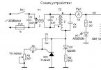
I made this charger for charging car batteries, the output voltage is 14.5 volts, the maximum charge current is 6 A. But it can also charge other batteries, for example, lithium-ion, since the output voltage and output current can be adjusted within wide limits. The main components of the charger were purchased on the Aliexpress website.
These are the components:
You will also need an electrolytic capacitor of 2200 uF at 50 V, a transformer for the TS-180-2 charger (see how to solder the TS-180-2 transformer), wires, a power plug, fuses, a radiator for a diode bridge, crocodiles. The transformer can be used with another one, with a capacity of at least 150 W (for a charging current of 6 A), the secondary winding must be rated for a current of 10 A and produce a voltage of 15 - 20 volts. A diode bridge can be recruited from individual diodes designed for a current of at least 10A, for example, D242A.
The wires in the charger should be thick and short. The diode bridge needs to be fixed to a large radiator. It is necessary to increase the heatsinks of the DC-DC converter, or use a fan for cooling.


Assembling the charger
Connect the cord with a mains plug and a fuse to the primary winding of the ТС-180-2 transformer, install the diode bridge on the radiator, connect the diode bridge and the secondary winding of the transformer. Solder a capacitor to the positive and negative terminals of the diode bridge.

Connect the transformer to a 220 volt network and measure the voltages with a multimeter. I got the following results:
- The alternating voltage at the terminals of the secondary winding is 14.3 volts (mains voltage is 228 volts).
- DC voltage after diode bridge and capacitor 18.4 volts (no load).
Referring to the diagram, connect a buck converter and a voltammeter to the DC-DC diode bridge.
Setting the output voltage and charging current
There are two trimming resistors on the board of the DC-DC converter, one allows you to set the maximum output voltage, the other can set the maximum charging current.
Connect the charger to the mains (nothing is connected to the output wires), the indicator will show the voltage at the output of the device, and the current is equal to zero. Set the voltage potentiometer to 5 volts. Close the output wires together, set the short-circuit current to 6 A. with the current potentiometer. Then remove the short circuit by disconnecting the output wires and with the voltage potentiometer, set the output to 14.5 volts.
This charger is not afraid of a short circuit at the output, but if the polarity is reversed, it may fail. To protect against polarity reversal, a powerful Schottky diode can be installed in the break of the positive wire going to the battery. Such diodes have a low voltage drop during direct connection. With this protection, if the polarity is reversed when connecting the battery, no current will flow. True, this diode will need to be installed on a radiator, since a large current will flow through it when charging.

Suitable diode assemblies are used in computer power supplies. In such an assembly there are two Schottky diodes with a common cathode, they will need to be paralleled. For our charger, diodes with a current of at least 15 A.

It should be borne in mind that in such assemblies, the cathode is connected to the case, therefore, these diodes must be installed on the radiator through an insulating gasket.
It is necessary to adjust the upper voltage limit again, taking into account the voltage drop across the protection diodes. To do this, use the voltage potentiometer on the DC-DC converter board to set 14.5 volts measured with a multimeter directly at the output terminals of the charger.
How to charge the battery
Wipe the battery with a cloth soaked in baking soda solution, then dry. Unscrew the plugs and check the electrolyte level, if necessary add distilled water. The plugs must be turned out during charging. Debris and dirt must not get inside the battery. The room in which the battery is being charged must be well ventilated.
Connect the battery to the charger and turn on the device to the mains. During charging, the voltage will gradually rise to 14.5 volts, the current will decrease over time. The battery can be conditionally considered charged when the charging current drops to 0.6 - 0.7 A.
Sometimes it happens that the battery in the car sits down and it is no longer possible to start it, since the starter does not have enough voltage and, accordingly, current to turn the engine shaft. In this case, you can “light up” from another car owner so that the engine starts up and the battery starts charging from the generator, but this requires special wires and a person who wants to help you. You can also charge the battery yourself using a specialized charger, but they are quite expensive and do not have to be used very often. Therefore, in this article we will take a closer look at a homemade device, as well as instructions on how to make a do-it-yourself car battery charger.
Homemade device
The normal voltage for a battery disconnected from the vehicle is between 12.5 volts and 15 volts. Therefore, the charger must supply the same voltage. The charge current should be equal to about 0.1 of the capacity, it can be less, but this will increase the charging time. For a standard battery with a capacity of 70-80 a / h, the current should be 5-10 amperes, depending on the specific battery. Our homemade battery charger must meet these parameters. To assemble a car battery charger, we need the following items:
Transformer. Any of the old electrical appliance or one bought on the market with an overall power of about 150 watts will suit us, more is possible, but not less, otherwise it will get very hot and may fail. It's great if the voltage of its output windings is 12.5-15 V, and the current is about 5-10 amperes. You can view these parameters in the documentation for your part. If the required secondary winding is not available, then it will be necessary to rewind the transformer for a different output voltage. For this:
Thus, we have found or assembled the perfect transformer to make a do-it-yourself battery charger.
We will also need:

Having prepared all the materials, you can proceed to the very process of assembling the car charger.
Assembly technology
To make a do-it-yourself car battery charger, you must follow the step-by-step instructions:
- We create a homemade charging circuit for the battery. In our case, it will look like this:

- We use the TS-180-2 transformer. It has multiple primary and secondary windings. To work with it, you need to connect in series two primary and two secondary windings in order to obtain the desired voltage and current at the output.

- Using a copper wire, we connect pins 9 and 9 'together.

- On a fiberglass plate, we assemble a diode bridge from diodes and radiators (as shown in the photo).

- Conclusions 10 and 10 'are connected to the diode bridge.
- Install a jumper between pins 1 and 1 '.

- We attach the power cord with a plug to pins 2 and 2 'using a soldering iron.
- We connect a 0.5 A fuse to the primary circuit, and a 10-amp fuse, respectively, to the secondary.
- In the gap between the diode bridge and the battery, we connect an ammeter and a piece of nichrome wire. One end of which is fixed, and the other must provide a movable contact, thus the resistance will change and the current supplied to the battery will be limited.
- We insulate all connections with heat shrink or electrical tape and place the device in the case. This is necessary to avoid electric shock.
- We install a movable contact at the end of the wire so that its length and, accordingly, the resistance is maximum. And we connect the battery. By decreasing and increasing the length of the wire, it is necessary to set the desired current value for your battery (0.1 of its capacity).
- During the charging process, the current supplied to the battery will itself decrease and when it reaches 1 ampere, we can say that the battery is charged. It is also advisable to control directly the voltage on the battery, however, for this it must be disconnected from the charger, since during charging it will be slightly higher than the actual values.
The first start-up of the assembled circuit of any power source or charger is always carried out through an incandescent lamp, if it lights up at full incandescence - either there is an error somewhere, or the primary winding is closed! The incandescent lamp is installed in the gap of the phase or neutral wire supplying the primary winding.
This circuit of a homemade battery charger has one big drawback - it does not know how to independently disconnect the battery from charging after reaching the desired voltage. Therefore, you will have to constantly monitor the readings of the voltmeter and ammeter. There is a design that is devoid of this drawback, but its assembly will require additional parts and more effort.

An illustrative example of a finished product
Operating rules
The disadvantage of a homemade charger for a 12V battery is that after the battery is fully charged, the device does not automatically turn off. That is why you will have to periodically glance at the scoreboard in order to turn it off in time. Another important nuance - it is strictly forbidden to check the memory "for a spark".
Additional precautions include:
- when connecting the terminals, make sure not to confuse "+" and "-", otherwise a simple homemade battery charger will fail;
- connection to the terminals must be carried out only in the off position;
- the multimeter must have a scale of more than 10 A;
- when charging, unscrew the plugs on the battery in order to avoid its explosion due to boiling of the electrolyte.
Master class on creating a more complex model
That, in fact, is all that I wanted to tell you about how to correctly make a charger for a car battery with your own hands. We hope that the instructions were clear and useful for you, because this option is one of the simplest types of homemade battery charging!
Also read: