We apply lapping paste on the valve chamfer and install the valve in the corresponding guide sleeve of the cylinder head of the ZMZ 406 engine.
We fix the lapping device on the valve leg and ... 
... while pressing the valve against the seat, we rotate it alternately in both directions.

We continue lapping until the sealing chamfer of the valve completely along its entire width and length becomes dull and clean.
The chamfer on the valve seat should look the same.
Wipe off the remaining paste from the valve and seat with a rag.
We grind the rest of the valves in the same way. Before assembling the cylinder head of the ZMZ 406 with kerosene or diesel fuel, we rinse the head, clean the oil channels from deposits. Then we wipe the surfaces with a clean cloth and blow through the channels with compressed air.
We assemble and install the ZMZ 406 cylinder head in reverse order. The valve stem seals are replaced with new ones. Before installing the valves, coat their rods with engine oil.
Remove oil and coolant residues from the threaded holes of the cylinder block for the head mounting screws.

Apply sealant to the mating plane of the front cover of the cylinder block (in the area of contact with the head gasket).
We replace the gasket of the cylinder head of the ZMZ 406 engine with a new one. When installing the cylinder head on the block, make sure that it "sits" on the dowel sleeves. Before installing the screws for securing the cylinder head, apply engine oil to their threaded part.
We tighten the screws with a torque wrench in two stages, observing the sequence of tightening them. Pre-tighten them with a torque of 50 Nm, then finally - 140 Nm. 
The order of tightening the cylinder head bolts
Having installed all the removed parts and assemblies, we fill the cooling system with liquid and replace the oil in the engine
Diagram of installation and stamping of camshaft covers
I - front cover;
II - intake valve shaft;
III - exhaust valve shaft.
SEQUENCING
We remove the tips from the spark plugs along with the high-voltage wires.

Remove the ignition coils (see Checking and replacing the ignition coils). The coils can be left on the cover by disconnecting the low voltage wires from them.
Disconnect the throttle and air valve drive cables from the carburetor (see Removing the carburetor).
Remove the grille and upper grille panel (see Removing the grille and Removing the upper grille panel).
We disconnect the wires from the oil temperature and pressure sensors (see Replacing the temperature gauge sensors, Replacing the oil pressure sensors), bend the wire brackets ...
… And remove the wires from the engine.

We loosen the clamp and disconnect the small hose of the crankcase ventilation system.

Using a 12 key, unscrew the eight bolts securing the block head cover.

Remove the cover.

Turning the crankshaft with the head "at 36", we set it to the TDC position of the compression stroke of the first cylinder, (the risk on the crankshaft pulley must coincide with the protrusion on the front cover of the cylinder block, ...

... and the marks on the camshaft sprockets must be turned in opposite directions and be in line with the upper edge of the cylinder head.

ATTENTION
Do not turn the crankshaft during further work.
For convenience, we remove the fuel pump (see Removing the fuel pump of the ZMZ-4063 engine) and, without disconnecting the hoses, take it to the side (you can leave the fuel pump on the cover).
Using the 12 key, unscrew the four bolts (the two lower ones are short).

Remove the front cylinder head cover ...

And a gasket.

Using a 6-key hexagon wrench, unscrew two screws ...

... and remove the upper damper of the upper chain.

With the same wrench, unscrew the two screws securing the middle damper.

We loosen the chain tension in the area near the middle damper by turning the exhaust valve shaft clockwise with a "17" wrench for the sprocket mounting bolt (or with a "30" wrench for a square on the shaft).

We remove the middle soot.

Holding the exhaust valve shaft with a "30" wrench, with a "17" wrench, unscrew the sprocket mounting bolt.

Remove the sprocket from the exhaust valve shaft.

Similarly, we unscrew the bolt securing the intake valve shaft sprocket.
Remove the eccentric of the fuel pump drive ...

… And an intake sprocket.

Using the "12" head, unscrew the four bolts securing the front camshaft cover.

Removing the front cover ...

... and plastic inserts for limiting the axial movement of the camshafts.

Using the "12" head, sequentially, half a turn, loosen the tightening of the camshaft cap bolts until the valve springs stop pressing the shafts.

Finally, we unscrew the bolts and remove the covers.

We remove the camshaft.

Remove the second camshaft in the same way.
Before installing the camshafts, lubricate their bearing journals, cams, as well as beds in the head and covers with engine oil.
Install the exhaust valve shaft with the pin to the right (looking from the front), and the intake valve shaft with the pin up. In this case, the shafts are in a stable position (for clarity, the radiator hose has been removed).

The intake and exhaust camshafts are interchangeable, but ...
ATTENTION
Pay attention to the correct position of the pins in the holes in the camshaft flanges.
We install each cover in its place, according to the serial number stamped on it.
We orient the covers so that the number embossed on them is facing the outside of the head.

We tighten the cover fastening bolts with a torque of 1.9-2.3 kgf.m, after which ...
… We turn the intake valve shaft so that its pin is located opposite the upper edge of the block head.

We install sprockets with a chain on the shafts, starting from the exhaust camshaft.
With a tensioned branch of the chain on the side of the middle damper, the mark on the sprocket should be located opposite the upper edge of the block head.

We put the middle damper in place and put the second asterisk.
We carry out further assembly in the reverse order of disassembly.
ATTENTION
After installing the hydraulic tensioner ...
We check the coincidence of all marks on the crankshaft pulley and sprockets. Otherwise, remove the incorrectly installed sprocket and, having moved it to one section of the chain, reinstall it.
:Pre-tightening;
Exposure not less than 1 min 15 sec;
Rotation at an angle of 90
Bolts of fastening of a head of cylinders to a cover of a chain
Camshaft cover retaining bolts
Crankshaft pinch bolt
170-220 (17,0-22,0)
Camshaft sprocket retaining bolts
Intermediate shaft sprocket retaining bolts
2. Other connections:
Crankshaft dirt trap plugs
Seal holder retaining bolts
Lower chain guide bolts
Middle and upper chain guide bolts
Chain Tensioner Support Bolts
Chain Tensioner Lever Bolts
Hydraulic tensioner cover bolts
Front and rear cylinder head cover retaining bolts
Oil pan retaining bolts
Oil pan retaining nuts
Clutch Booster Bolts
Oil filter connection
Oil pump drive cover bolts
Designation in JSC "ZMZ"
|
Connection name |
Number of connections |
Tightening torque, Nm (kgfm) |
|
Thermostat housing to cylinder head screws |
|
|
|
Screws and nuts for securing chain cover and water pump |
|
|
|
Bolt of fastening of the water pump to the chain cover |
||
|
Exhaust manifold retaining nuts |
||
|
Intake pipe retaining nuts |
||
|
Receiver mounting nuts |
||
|
Valve cover retaining bolts |
||
|
Automatic accessory drive belt tensioner retaining screw |
||
|
Cooling hose clamps |
3,9-6,0 (0,39-0,6) |
|
|
Clutch housing retaining bolts |
||
|
Clutch fork support bolt |
||
|
Starter mounting bolts |
||
|
Nuts for fastening the generator to the upper and lower brackets |
||
|
Nut for fastening the pulley on the generator shaft |
||
|
Spark plug |
||
|
Ignition coil retaining nuts |
||
|
Knock sensor retaining nut |
20 0.5 (2.0 0.05) |
|
|
Coolant temperature sensor |
||
|
Oil pressure warning switch |
||
|
Throttle mounting screws |
||
|
Fuel line retaining screws with injectors |
||
|
Timing sensor bolt |
||
|
Phase sensor bolt |
||
|
Parts not listed with tapered threads: |
||
|
Connection name |
Number of connections |
Tightening torque, Nm (kgfm) |
Appendix 3
Rolling bearings used in the ZMZ-40524 engine
|
Bearing name |
Designation |
Quantity, pcs. |
|
Toe of the input shaft of the gearbox (in the flywheel): |
||
|
Single row deep groove ball with two shields or |
402.1701031 (6203ZZ.P6Q6 / US9) |
|
|
Single row deep groove ball with double-sided sealing |
402.1701031-01 (6203.2RS.P6Q6 / US9) or 402.1701031-02 (6203.2RS2.P63Q6 / U.C30) |
|
|
Tensioner lever with sprocket assembly with bearing |
||
|
Automatic tensioning mechanism for the drive belt of the units assembled with a roller with a bearing |
Engine cuffs
Appendix 4
|
Name |
Designation |
Quantity, pcs. |
|
Front crankshaft seal |
f. "Rubena", Czech Republic |
|
|
Rear crankshaft seal |
406.1005160-03, OJSC VELKONT, Kirovo-Chepetsk or 2108-1005160, JSC "Balakovorezinotekhnika", Balakovo or 4062.1005160 * (546.941), f. "Elring", Germany or 4062.1005160-01 * (03055VOOA), f. "Rubena", Czech Republic |
|
|
Water pump seal |
40522.1307020 * (94412) f. "MTU", Italy |
|
Oil deflector cap, intake and exhaust valves, assy |
406.1007026-03 * (648.32G) f. "Rubena", or 406.1007026-04 * (2108-1007026-02), OJSC "VELKONT", Kirovo-Chepetsk |
|
|
Crankshaft toe seal ring |
406.1005044* (038-044-36-2-2 GOST 18829-79) |
Appendix 5
Unbalance of rotating parts allowed when assembling the engine
|
|
Balancing method |
Permissible imbalance, g cm, no more |
How to eliminate the imbalance |
|
Crankshaft |
Dynamic |
in planes passing through the extreme radical necks |
Drilling holes ¯ 14 mm to a depth of not more than 25 mm in the radial direction from counterweights. The intersection of the holes and the exit on the surface of the ends of the counterweights is not allowed |
|
Rice. 3.6. Crankshaft balancing: - the base for installing the crankshaft on the machine; - clamp |
|||
|
Pulley - crankshaft damper |
Static |
Drilling holes ¯ 10 mm to a depth of not more than 12 mm, taking into account the cone of the drill in the damper disc in the radial direction at a distance of 10.5 mm from the rear plane. The distance between the axes of the holes is not less than 18 mm |
|

|
Rice. 3.7. Balancing the damper pulley: 1 - pulley damper; 2 - mandrel; 3 Static balancing device |
|||
|
Flywheel with rim |
Static |
Drilling holes Ø 14 mm to a depth of no more than 12 mm, taking into account the cone of the drill on the side opposite to the clutch attachment at a radius of 115 mm. Drill a maximum of 10 holes. Distance between axles not less than 18 mm |
|
|
Rice. 3.8. Flywheel balancing: 1 - flywheel; 2 - mandrel; 3 - device for static balancing |
|||
|
Clutch pressure plate assy |
Static |
50 - when checking 15 - when balancing |
Installation of balancing weights in the holes of the casing flange or drilling in the casing flange with a diameter of 273 holes Ø 9 mm between the holes for the weights |
|
Clutch disc assy |
Static |
30 - when checking 15 - when balancing |
Installation of balancing weights |


Appendix 6
Tools and accessories for engine repair Tools developed by JSC "ZMZ"
|
Designation |
Name |
|
Puller for crankshaft damper pulley |
|
|
Tool for pressing the gear and hub onto the crankshaft |
|
|
Crankshaft sprocket and bushing remover |
|
|
Crankshaft sprocket pressing tool |
|
|
Mandrel for pressing in oil seals |
|
|
Device for drying and drying valves |
|
|
Pliers for removing and installing piston rings Ø 95.5 mm |
|
|
Mandrel for compression of piston rings Ø 95.5 mm |
|
|
Oil filter wrench |
|
|
Clutch disc centering tool |
|
|
Mandrel for pressing on valve stem seals |
The tool developed by JSC "GAZ"
|
Designation |
Name |
|
Tool for removing and installing the crankshaft damper pulley and removing the crankshaft sprocket |
|
|
Set of mandrels for pressing on valve stem seals |
|
|
Oil filter wrench |
|
|
Adapter for special tool 6999-7697 for installing a crankshaft damper pulley |
|
|
Tool for removing the bearing of the front end of the gearbox shaft from the flywheel |
|
|
Gearbox shaft front end bearing remover from flywheel (in conjunction with tool 6999-7810) |
|
|
Clamp for compression of valve spring |
|
|
Adapter for clamp 6999-7931 for compression of the valve spring |
|
Designation |
Name |
|
Oil filter remover |
Appendix 7
Engine fluids
|
Brand name and designation |
Change frequency |
Volume refilled into the product |
Note |
|||
|
The main |
Duplicate |
Foreign |
Main brand |
Duplicating Aya mark |
||
|
Fuel: |
Unleaded gasoline 91 ... 93 RON (RON - research octane) |
|||||
|
"Regular Euro-92" GOST R 51866 |
"Premium Euro-95" or "Super Euro-98" GOST R 51866 |
|||||
|
Motor oil according to STO AAI 003: |
Motor oil according to SAE J 300, API 2 : |
Dry engine excluding radiator filling volume |
Application temperature range: |
|||
|
SAE 0W-30, API SL |
from minus 30 ° С to plus 20 С |
|||||
|
SAE 0W-40, API SL |
from minus 30 ° С to plus 25 С |
|||||
|
SAE 5W-30, API SL |
from minus 25 ° С to plus 20 С |
|||||
|
SAE 5W-40, API SL |
from minus 25 ° С to plus 35 С | |||||
Tightening the cylinder head bolts is an important part of the repair work that must not be overlooked. The question should be given attention, especially when it comes to the GAZ 53 car. We suggest you find out what is the tightening torque of the GAZ 53 cylinder head and what is the order of tightening the screws during repair.
[Hide]
When should you tighten?
Not every car enthusiast realizes the importance of this nuance. And not all drivers understand that the order of tightening the pins must be observed. This moment is important, and it is not recommended to neglect it. If you are the owner of a GAZ 53 and have not tightened the cylinder head screws correctly, this may cause other malfunctions. Accordingly, repairing the engine will entail a lot of money.
Truck GAZ 53
Ten years ago, the procedure in a vehicle was carried out by specialists in the maintenance of a car. The legislation was amended, according to which this procedure was canceled. Now tightening the screws is a headache for car owners. In what cases should it be performed?
- If you notice that a consumable is leaking from under the cylinder head, namely engine oil. In some cases, this can be the result of mechanical damage to the head gasket. Or the gasket could simply wear out. But sometimes oil leakage occurs as a result of loosening the cylinder head screws.
- If you disassemble the engine of your GAZ 53. When assembling and installing the cylinder head, the torque and order of tightening the screws must be observed in any case. If this is not done, then during long-term operation of the cylinder head, its deformation may occur.
If you see that the bolts can be tightened, then this should be done. The cylinder head screws can be loosened arbitrarily during vehicle operation. Therefore, it is necessary to diagnose tension every 3 thousand kilometers.
Process and order
Our resource advises novice motorists to think before tightening the cylinder head pins with their own hands. In practice, novice motorists, having no experience, begin the procedure without realizing how sad it can turn out to be. Of course, in case of wrong actions. Consider this procedure for a GAZ 53 car. Remember that each individual engine has its own nuances in operation.
Required tools
If you have already installed the cylinder head in place, then a whole set of tools is not needed. One tool must be prepared for tightening - a torque wrench. It is needed to perform work, since it is possible to correctly determine the moment only with the help of it. At home, very few people have such a tool, since it has a certain specificity of work. You can try to ask the masters at the service station, but not for free. If you decide to purchase such a key for yourself, please note that its cost is at least 1,200 rubles or 350 hryvnia.

One more tip. Sometimes "auto experts" who do not understand much advise not to use a torque wrench, but to use a regular wrench. They motivate this by the fact that the screws need to be tightened to the maximum, and buying a torque tool is a waste of money. We can say that they do not realize the seriousness of the situation. Therefore, if you want the repair process to go right, stock up on a torque wrench.
Step by step instructions
If you are the owner of GAZ 53, we recommend using the service manual for the car. Perhaps the engine of your GAZ 53 has certain nuances in its work or its own specifics. The instruction below is relevant for all GAZ 53. If you are ready to perform these works, you can proceed. If you changed the gasket or made repairs to the motor, then reassemble it and install a new seal.
- Inspect the cylinder head bolts. They should be in perfect condition. If the screws show mechanical damage or traces of deformation, they must be replaced. Re-use of the bolts is not recommended, but if their condition is perfect or close to it, then the operation of the pins is allowed. Pay attention to the thread - it must be clean. So are the pin sockets. If you notice dirt or metal shavings on the elements, they must be cleaned with a wire brush.
- The pins should be lubricated before tightening; engine fluid is suitable for this.
- Insert the screws into the holes and tighten them according to the order in the diagram. Using a torque wrench, all pins must be tightened with a torque of 7.3 - 7.8 kgm. Observe the order when doing this. If the temperature in the room where you are carrying out the repair is minus (below -5 degrees), then the cylinder head tension moment should be 7.3 kgm. If it is 20 degrees, then the tightening torque should be at the lower limit.
After that, the repair process of tightening the cylinder head screws can be considered complete. Recall that during such a repair, you need to be careful, non-observance of the nuances will lead to a negative result. Overtightening the pins can cause microcracks to appear on the motor housing. As you might guess, this will result in an expensive renovation. You will need to weld cracks or change the cylinder head itself.
Remember that the pins must be of good quality. The absence of cracks, metal dust, deformation is a prerequisite, which is important to adhere to during such work. If you cannot answer to yourself exactly whether you can do everything correctly, do not take the broach.
Video "Tightening the cylinder head pins"
Page 1 of 2
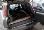
The head of the block can be removed with a receiver and an exhaust manifold.
If the head of the block is removed from the engine installed on the car, you must first perform the operations specified in the subsection "Removing and installing the engine".
You can also see the article - "Replacing the cylinder head gasket".
Then disconnect the front muffler pipe from the exhaust manifold, disconnect the hose from the throttle body, remove the radiator inlet pipe, remove the generator.
Remove the camshafts.
Loosen clamps 1 and detach hoses 2 and 3 from the throttle body fittings.
Remove thermostat with housing.
Remove spark plugs.
Unscrew bolts 1 securing the block head. Remove bolts 1 and washers.
Remove the cylinder head and the head gasket.
Do not drive screwdrivers or any other tool between the cylinder head and the cylinder block, as this could damage the surface of the cylinder head adjacent to the cylinder block.
Disassembly
1. Unscrew the nuts 1 and remove the shield 5 of the phase sensor, the bracket 2 for lifting the engine and the exhaust manifold 6.
Remove the exhaust manifold gaskets. Unscrew bolt 3 and remove the 4-phase sensor.
Unscrew emergency oil pressure sensors 7 and oil pressure gauge 8.
2. Loosen the clamp 1 and remove the hose from the idle speed regulator connection.
Unscrew nuts 2 and remove reservoir 3 from inlet pipe.
Remove the reservoir gasket.
3. Unscrew nuts 1 and remove inlet pipe 2 together with injectors and fuel line.
Remove the inlet pipe gasket.
Unscrew bolts 1 and remove rear cover 2 of the block head.
Remove the cover gasket.
Take out hydraulic pushers 1 for valves.
It is more convenient to remove the hydraulic pushers with a magnet or a suction cup.
Hydraulic pushers must not be interchanged, therefore, before removal, they must be marked so that they can be installed in their place during assembly.
The hydraulic pushers should be stored in the same position in which they are on the valves so that oil does not leak from them.
Install a valve spring compressor on the block head.
Squeezing the valve springs with a tool, remove the 2 valve crackers.
Then, gradually loosening the pressure on the handle of the device, completely release the valve springs.
Remove the tool from the block head. Remove the valve spring plate 3. Then remove the outer and inner valve springs.
Remove valve stem seal 1.
7. Hook up with a screwdriver and remove the support washer 1 of the valve springs.
8. Remove the valve from the side of the combustion chamber.
9. Remove the remaining valves in the same way.
Before removing, mark all valves so that they can be re-assembled during assembly.
avtomechanic.ru
Repair of the cylinder head ZMZ-405, ZMZ-406
Page 1 of 2
We repair the cylinder head during general engine repairs and when replacing the cylinder head gasket.
It is very important to repair the head after the motor has overheated. During overheating, defects may occur that cannot be visually seen. Therefore, you need to carefully do all the cylinder head repair operations. The operation of the engine largely depends on this. And it saves you unnecessary work and costs.
We look at the removal of the cylinder head in the article - "Replacing the cylinder head gasket".
Disassembly
|
1. Unscrew the nuts 1 and remove the phase sensor shield 5, the bracket 2 for lifting the engine and the exhaust manifold 6. Remove the exhaust manifold gaskets. Unscrew bolt 3 and remove the 4-phase sensor. Unscrew emergency oil pressure sensors 7 and oil pressure gauge 8. |
2. Loosen the clamp 1 and remove the hose from the idle speed regulator connection. Unscrew nuts 2 and remove reservoir 3 from inlet pipe. Remove the reservoir gasket. |
|
3. Unscrew the nuts 1 and remove the inlet pipe 2 together with the injectors and the fuel line (not shown in the photo). Remove the inlet pipe gasket. |
4. Unscrew the bolts 1 and remove the rear cover 2 of the block head. |
| Remove the cover gasket. | 5. Take out the hydraulic pushers 1 of the valves. It is more convenient to remove the hydraulic pushers with a magnet or a suction cup. |
|
Hydraulic pushers must not be interchanged, therefore, before removal, they must be marked so that they can be installed in their place during assembly. The hydraulic pushers should be stored in the same position in which they are on the valves so that oil does not leak from them. |
If the design of the puller does not provide for a valve stop, place a suitable stop under it. |
|
We compress the springs with a desiccant. To make the spring plate easier to come off the crackers, you can strike a light blow with a hammer on the persistent bipod of the drying machine. |
|
|
Remove the slinger cap with a puller ... |
|
|
Hook up with a screwdriver and remove valve spring support washer 1. |
We turn the cylinder head over and take out the valve, marking the place of its installation, so that during the subsequent assembly the valve will fall into its original place. Similarly, remove and mark the rest of the valves. |
|
Press out the worn valve guides with a mandrel. |
Unscrew the plugs of the oil channels with a hexagon wrench “8”. |
autoruk.ru
re-broaching the cylinder head
Hello again :) However, I am often asked, “do I need to re-broach the cylinder head?”. There are many who believe that they put the head on, tightened it and do not touch it anymore.
In the process of my rather long work as a minder, and this is already more than a quarter of a century, I was convinced from my own experience that if you are too lazy to stretch the head through the time set for pulling it, then after a while, and this largely depends on the driving style driver and distance traveled at the same time, you will have to shoot.
Usually the gasket burns out within a year, and if a person travels a long distance, then in a month. Therefore, my advice is this: you cannot go far with the head not extended, otherwise you will have to take it off on the road. But you know, I noticed that if the equipment came directly from the factory, then after the mileage set for broaching, the heads rarely weaken. It is possible that the material of the gasket, which is put there, is different.
So how long does it take to pull the cylinder head? On average, after a thousand km. mileage. This is written in the instructions and this is confirmed by practice. In the instructions for so. it is also written that after ten thousand it is necessary to stretch again or check the broaching of the head.
Well, in most cases, one broach was enough. But rarely, of course, but there were cases that when the gasket burned out, the head was weak even after one broach. In my opinion, it all depends on the material of the cylinder head gasket, which shrinks a lot, and which does not sag at all.
The physics of this phenomenon, namely the weakening of the head broach, is obvious. Typically, the cylinder heads are aluminum, and the bolts or studs are still steel. When heated, the expansion coefficient of aluminum is greater than that of steel, and when the engine heats up, the head expands and squeezes the gasket like a press, and when it cools down, it also releases the gasket, and the bolts are esessno loosened.
There is a rule: you cannot pull a hot engine, only a cold one. I will tell you a list of engines that you need to stretch from my experience that I dealt with, namely: zmz405,406,409. engines Zmz-402, UAZ 417.421. Engines zmz 511,512,523, zil-130, Ural.
I will not say about others, but usually VAZ heads rarely sink. I can’t say anything about foreign cars either, because I’ve looked through them a little, and I don’t want to f *** in vain. That's all for now.
There is more to come. In order not to suffer with the repeated broaching of the head, you have to disassemble almost half of the engine in order to make sure that it has not weakened, but sometimes it happens. Depends on the gasket material. You can't guess right away.
In order not to re-stretch the heads, you can put a metal package. You can read about it here. And although I wrote about the UAZ-patriot, this may apply to many engines. Good luck friends!
gazung.ru
Tightening torques of the main threaded connections ZMZ 402, ZMZ-4021, ZMZ-4062
Timing gear cover retaining bolt 11-16 (1.1-1.6) Timing gear cover retaining nut 12-18 (1.2-1.8) Pusher box cover retaining nut 12-18 (1.2-1.8 ) Cylinder head mounting nut 85-90 (8.5-9.0) Cylinder head rear cover mounting bolt 11-16 (1.1-1.6) Connecting rod cover bolt nut 68-75 (6.8- 7.5) Flywheel nut 78-83 (7.8-8.3) Crankshaft pulley retaining bolt 11-16 (1.1-1.6) Crankshaft tightening bolt (ratchet) 170-220 (17-22 ) Camshaft thrust flange mounting bolt 11-16 (1.1-1.6) Camshaft gear mounting bolt 55-60 (5.5-6.0) Rocker arm shaft mounting nut 35-40 (3.5- 4.0) Rocker arm cover bolt 4.5-8.0 (0.45-0.8) Exhaust manifold-to-intake pipe nut 44-56 (4.4-5.6) Intake pipe and exhaust manifold retaining nut to the block head 40-56 (4.0-5.6) Oil sump nut 12-15 (1.2-1.5) Oil pump retaining nut 18-25 (1.8 -2.5) Ignition distributor drive retaining bolt 6.0-8.0 (0.6-0.8) Main bearing cap retaining nut 100-110 (10-11) Oil filter retaining nut 12-18 (1.2 -1.8) Fuel pump mounting bolt 12-18 (1.2-1.8) Fine fuel filter mounting nut 12-18 (1.2-1.8) Water pump mounting nut 18-25 (1.8 -2.5) Water pump pulley mounting bolt 12-18 (1.2-1.8) Clutch housing mounting bolt 28-36 (2.8-3.6) Clutch housing mounting nut 40-56 (4.0- 5.6) Clutch pressure plate retaining bolt 20-25 (2.0-2.5) Alternator bracket retaining nut 44-62 (4.4-6.2)
Alternator retaining nut 44-56 (4.4-5.6) Spark plug 30-40 (3.0-4.0) Fan retaining bolt 14-18 (1.4-1.8)
Main bearing cap bolt 100-110 (10.0-11.0) Connecting rod cap bolt nut 68-75 (6.8-7.5) Flywheel bolt 72-80 (7.2-8.0) Bolt cylinder head mountings:
- first stage 40-60 (4.0-6.0) - second stage 130-145 (13.0-14.5) Camshaft cover retaining bolt 19-23 (1.9-2.3) Crankshaft tightening bolt Shaft (Ratchet) 104-128 (10.4-12.8) Camshaft Gear Bolt 56-62 (5.6-6.2) Intake Pipe Nut 29-36 (2.9-3.6) Cylinder head front cover retaining bolt 22-27 (2.2-2.7) Water pump pulley retaining bolt 22-27 (2.2-2.7) Water pump retaining bolt 22-27 (2.2-2, 7) Bolt of fastening of gears of the intermediate shaft 22-27 (2.2-2.7) Nut of fastening of the receiver to the intake pipe 19-23 (1.9-2.3) Nut of fastening of the exhaust manifold 20-25 (2.0- 2.5) Oil sump mounting bolt 12-18 (1.2-1.8) while ensuring tightness, a torque of 6 Nm (0.6 kgfm) is allowed
Bolt for fastening the cylinder head cover 5.0-8.0 (0.5-0.8) while ensuring tightness, a torque of 3 Nm (0.3 kgfm) is allowed. 1.8) Bolt for fastening the fuel line with injectors 5.0-8.0 (0.5-0.8) Bolt for fastening inductive sensors 5.0-8.0 (0.5-0.8) Spark plug 31-38 (3.1-3.8) Starter mounting bolt 67-75 (6.7-7.5) Alternator bracket mounting nut 12-18 (1.2-1.8) Clutch pressure plate mounting bolt 20-25 (2 , 0-2.5) Clutch housing mounting bolt 42-51 (4.2-5.1) Clutch housing amplifier mounting bolt 29-36 (2.9-3.6) Clutch release fork support mounting bolt 42-51 ( 4.2-5.1)
Other compounds
Tie rod tube clamp nut 15-18 (1.5-1.8) Front lower arm pin 180-200 (18-20) Front upper arm axle nut 70-100 (7.0-10.0) Nut pin of the threaded joint 120-200 (12.0-20.0) Bolt and nut of the axle of the upper levers 44-56 (4.4-5.6) Bolt of fastening of the wheel 100-120 (10-12) Nut of the flange of the rear drive gear axle 160-200 (16-20) Bolt for fastening the front suspension to the body 125-140 (12.5-14) Nut for fastening the steering mechanism 50-60 (5.0-6.0) Nut for fastening the steering wheel 65-75 ( 6.5-7.5) Nut for fastening the bipod of the steering mechanism 105-120 (10.5-12) Bolt for fastening the swingarm bracket 50-62 (5.0-6.2) Bolt and nut for fastening the steering column to the dashboard 12-18 (1.2-1.8) Steering wedge nut 18-25 (1.8-2.5) Power steering pump suction port 32-40 (3.2-4.0) Valve union bolt control of the built-in power steering 80-100 (8.0-10.0) Top and bottom tilt nut Built-in power-assisted steering pressure hose fitters 44-62 (4.4-6.2) Nut of the upper and lower tips of the built-in power-assisted steering pressure hose 44-62 (4.4-6.2) Nut of the built-in power steering drain hose tube 44-62 (4.4-6.2) Nut for connecting the tip of the delivery hose and hoses of the power cylinder of the separate power steering 32-40 (3.2-4.0) Bolt-union of the drain hose of the built-in power steering 80-100 ( 8.0-10.0) Bolt for fastening the steering knuckle, lever and bracket 80-100 (8.0-10.0) Turn stop 80-100 (8.0-10.0) Nut for fastening the axle of the brake and clutch pedal pusher 32-36 (3.2-3.6) Rear brake shield mounting bolt 65-80 (6.5-8.0) Front brake caliper mounting bolt 110-125 (11.0-12.5)
Rear brake wheel cylinder retaining bolt 8.0-18.0 (0.8-1.8) Rear brake pressure regulator retaining nut 8.0-18.0 (0.8-1.8) Brake master cylinder retaining nut 24- 56 (2.4-5.6) Vacuum booster retaining nut 8.0-18.0 (0.8-1.8) Rear propeller shaft splined yoke retaining bolt 50-56 (5.0-5.6) Nut fastening the propeller shaft to the rear axle 27-30 (2.7-3.0) Nut for fastening the intermediate support cross member to the body 27-30 (2.7-3.0) Bolt fastening the intermediate support to the cross member 12-18 (1.2 -1.8) Nut for fastening the gearbox to the clutch housing 50-62 (5.0-6.2)
For other screw connections, the tightening torques are as follows:
for М6 - 6–8 Nm (0.6–0.8 kgf · m) for М8 - 14–18 Nm (1.4–1.8 kgf m (2.8-3.6 kgf · m) for М12 - 50–62 N · m (5.0-6.2 kgf · m)
This is how the overtightened bolt looks like :)
gaz-autoclub.ru
Replacing the camshafts of the ZMZ-406 engine
Page 1 of 2
1. Remove the spark plug tips along with high-voltage wires, ignition coils (you can only disconnect the connectors, leaving them on the valve cover), the throttle cable and, having disconnected the wires from the lubrication and cooling system sensors, remove the wiring harness from the head cover brackets.
2. We drain the coolant and remove the upper radiator hoses and the mass air flow sensor together with the air ducts.
7. With the head at 36, we set the crankshaft to the TDC position of the compression stroke of the first cylinder, turning it by the pulley bolt (the risk on the crankshaft pulley should coincide with the protrusion on the front cover of the cylinder block, and the marks on the camshaft sprockets - at the upper edges of the head block).
|
8. With a 12 key, unscrew the four bolts and remove the front cover of the block head. 9. Remove the upper hydraulic tensioner (see Removing and installing hydraulic tensioners). |
10. Using a 6 hexagon wrench, unscrew the two screws and remove the upper chain damper. |
|
11. Having unscrewed two screws with a 6-point wrench, remove the middle chain damper. |
12. With a 17 key, unscrew the bolt securing the exhaust camshaft sprocket, holding the shaft with a 30 key. |
|
13. Remove the asterisk. Similarly, remove the sprocket from the second camshaft. |
14. With a 12 key, unscrew the four bolts securing the front camshaft cover. Sequentially, by half a turn, we loosen the tightening of the camshaft cover bolts until the valve springs stop pressing the shafts and unscrew the bolts. |
avtomechanic.ru
Removal and repair of the cylinder head of the engine zmz 406
We drain the coolant from the system (see "Replacing the coolant"). We remove the hoses from the thermostat nozzles or remove the thermostat
(see Checking and replacing the thermostat "). Disconnect the block of wires from the camshaft position sensor
(see "Checking and replacing the camshaft position sensor"). Remove the generator with its upper bracket (see "Removing the generator"). If we dismantle the cylinder head of the ZMZ 406 engine for repair or replacement, then first remove the intake manifold (see "Replacing the intake manifold gasket") and the exhaust manifold (see "Replacing the exhaust manifold gaskets"). If the work is done for a different purpose (for example, you need to replace the cylinder head gasket), then the head can be removed as an assembly with the intake pipe and exhaust manifold. We remove the camshafts (see "Removing the camshafts"). With a "12" hexagon, we unscrew the ten screws that secure the cylinder head of the ZMZ 406 engine.
and take out the screws.
We take out the washers of the screws.
We take out the hydraulic lifters (see "Replacing hydraulic lifters"). by marking their location in the cylinder head. Remove the cylinder head.
and its gasket.
We thoroughly clean the mating surfaces of the head and the cylinder block from carbon deposits, remnants of the old gasket and sealant. Attaching a straight edge to the cylinder head mating plane.
using a set of probes, we check the flatness of the cylinder head. If the flatness is more than 0.05 mm, the plane of the head must be restored by machining, however, if the non-flatness exceeds 0.1 mm, the head is not repairable.
Using the "10" wrench, unscrew the eight bolts.
remove the rear cylinder head cover with a gasket.
We install the desiccant on the cylinder head. If the valve stop is not provided for by the design of the desiccant, place a wooden block under the valve disc. With a desiccant, we squeeze the valve springs. To make the spring plate easier to come off the crackers. we apply light blows with a hammer to the persistent bipod of the drying agent.
We take out two crackers with tweezers and smoothly release the springs.
Remove the top plate and two valve springs.
Remove the slinger cap with a puller.
and remove the support washer.
We turn over the cylinder head of the ZMZ 406 engine and take out the valve, marking the place of its installation, so that during the subsequent assembly the valve will fall into its original place. Similarly, remove and mark the rest of the valves. Unscrew the plugs of the oil channels with a hexagon "8".
For lapping valves.
we apply lapping paste on the valve chamfer and install the valve in the corresponding guide sleeve of the cylinder head of the ZMZ 406 engine.
We fix the lapping device and on the valve leg.
pressing the valve to the saddle, turn it alternately in both directions.
We continue lapping until the sealing chamfer of the valve completely along its entire width and length becomes dull and clean.
The chamfer on the valve seat should look the same.
Wipe off the remaining paste from the valve and seat with a rag.
We grind the rest of the valves in the same way. Before assembling the cylinder head ZMZ 406 with kerosene or diesel fuel, we rinse the head, clean the oil channels from deposits. Then we wipe the surfaces with a clean cloth and blow through the channels with compressed air.
We assemble and install the cylinder head ZMZ 406 in the reverse order. The valve stem seals are replaced with new ones. Before installing the valves, coat their rods with engine oil.
Remove oil and coolant residues from the threaded holes of the cylinder block for the head mounting screws.
Apply sealant to the mating plane of the front cover of the cylinder block (in the area of contact with the head gasket).
We replace the gasket of the cylinder head of the engine ZMZ 406 with a new one. When installing the cylinder head on the block, make sure that it "sits" on the dowel sleeves. Before installing the screws for securing the cylinder head, apply engine oil to their threaded part. We tighten the screws with a torque wrench in two stages, observing the sequence of tightening them. Pre-tighten them with a torque of 50 Nm, then finally - 140 Nm. The order of tightening the cylinder head bolts
Having installed all the removed parts and assemblies, we fill the cooling system with liquid and replace the oil in the engine
Overhaul of the cylinder head ZMZ 406, 405, 409 for gas.
Cylinder head repair
note2auto.ru
Do-it-yourself cylinder head broaching "AvtoNovator
As we have already found out, the cylinder head is one of the most important engine components. If you feel confident and have the skills to use a locksmith tool, then broaching the cylinder head will not be difficult. It remains to decide for what and how to draw the cylinder head.
When you need a cylinder head broach
Maybe not all motorists know, but modern cars do not need preventive broaching of the cylinder head.
Previously, the cylinder head broaching was a mandatory item of the first maintenance, then the situation changed. Even relatively modern VAZ engines. Broaching the cylinder head is mainly required today for old models of VAZ, UAZ, Moskvich, etc. engines.

The main reason that prompts the owner of the car to think about the need to broach the cylinder head is "sputum" at the junction of the head and the block. This indicates an existing oil leak.

There may be several reasons. The most traditional: failure of the cylinder head gasket, warpage of the cylinder head as a result of engine overheating unnoticed by you, or initially incorrectly tightened cylinder head bolts. If you got a "kapitalku" at a car service.
How to pull the cylinder head bolts
From the study. It is from the study of the Manual for the repair of your car, preferably the original one. It is there that the manufacturer indicates everything that is needed to tighten the cylinder head. But you need to know:
- the order (diagram) of tightening the cylinder head bolts;
- what torque is required;
- what bolts are used to tighten the cylinder head.
Bolts for tightening the cylinder head are a special conversation. The fact is that in modern engines, bolts with special characteristics are used for the cylinder head. The so-called "spring" bolts, which, due to their properties after the initial pull at the factory, do not need additional.

Moreover, when trying to pull the cylinder head bolts, due to the "fluidity" of the metal, they will stretch. As a result, you can get a break in the bolt.
During cylinder head repair, gaskets must be installed that do not shrink. This eliminates the need to pull the cylinder head bolts.

But, if you have already decided that broaching the cylinder head bolts is extremely necessary for you, then it should be done with the "manual" from the manufacturer and using a torque wrench. Motion in motion, digit to digit. Amateur performance on the basis of "reserve" is not needed here.
Cylinder head tightening control
To keep your soul calm, and as soon as you decide to broach the head bolts, there is a method for controlling the tightening torque of the cylinder head bolts. Naturally with a torque wrench.
A moment is applied to the bolt, equal to the moment of the bolt breaking away. After the start of the turn, you need to control the moment of starting. If it has not increased, then everything is in order, the bolt began to stretch.
If the moment starts to rise, it means that the bolt has not reached the yield point. Here you need to tighten the cylinder head bolt until the tightening torque stabilizes.

When checking the tightening of the cylinder head bolts, pay attention to two things. If a torque of 20 kgGcm is applied to the bolt, but the yield point has not been reached, then the bolt must be replaced, since it has increased strength.
If, at the moment of tightening the bolt, you saw that the moment decreases, then this means the destruction of the bolt, and it definitely requires replacement.
Such requirements for the cylinder head bolts can be easily explained: they work in a constant heating - cooling mode.

Good luck, and may the do-it-yourself cylinder head bolt tightening work well.