The spring-loaded lever clutch of UAZ-469, UAZ-469B and UAZ-469BG vehicles is designed to disconnect crankshaft engine and transmission when it is necessary to shift gears or brake the vehicle.
Spring lever clutch UAZ-469, device.
Spring-loaded lever clutch dry, single-disk, consists of a pressure plate with a casing, pressure springs and release levers as an assembly, a driven disk with friction linings and dampers torsional vibrations assembled. The clutch mechanism is bolted to the engine flywheel, balanced together with the crankshaft, and its position after balancing is marked on the casing and flywheel with the “O” icon.
Between the clutch cover and the pressure plate, pressure springs are installed, having heat-insulating washers on the side of the pressure plate. The clutch release device consists of release levers mounted on the pressure plate, a clutch release clutch with a thrust bearing mounted on the bearing cover input shaft, and a release fork mounted on the clutch housing.
The driven disk is mounted on the splines of the input shaft. The pressure plate, under the action of springs, presses the friction linings against the flywheel, the resulting friction forces make it possible to transfer torque from the engine crankshaft to the gearbox input shaft.

The drive is a system of levers and rods that connects the clutch release fork coming out of the clutch to the clutch pedal at the driver's workplace. The clutch pedal is pinned to the left end of the pedal shaft. With the clutch pedal on the shaft, the brake pedal is freely installed. The upper position of the pedals is determined by the emphasis on the buffer on the inclined floor of the body.
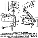
To lubricate the pedal assembly, a grease fitting is installed on the shaft. The drive lever is connected to the intermediate lever by means of an adjustable rod. The intermediate lever on the axle is locked with a spring ring and lubricated through a grease fitting. The smaller arm of the intermediate lever is connected to the pusher, which, with its spherical end, rests against the heel of the clutch release fork. The springs select the gaps in the mechanism and hold the parts in position - the clutch is on.
Maintenance of the spring-lever clutch UAZ-469.
Maintenance consists of cleaning from dirt, tightening bolted connections, adjusting and lubricating. After driving on muddy roads, clean the hole at the bottom of the clutch housing. Timely lubricate the clutch release bearing through the cap oiler located on the right side of the clutch housing.
It is carried out with the clutch pressure plate removed in the following sequence:
1. Install a 9.5 mm thick ring template between the plate and the pressure plate. Fasten the assembled pressure plate to the plate with six bolts.
2. Adjust by tightening and unscrewing the adjusting bolts until a size of 51.5 + -0.75 mm is obtained - the distance of the bolt heads from the surface of the plate. The difference in the distance from the plate to the bolt heads should not exceed 0.2 mm.
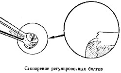
3. Lock the bolts of the levers after adjustment by bending the edge of the lever into the groove of the bolt shank.
Maintenance of the UAZ-469 clutch control drive.
It comes down to adjustment and periodic lubrication of friction units through two grease fittings. The clutch release drive is adjusted by changing the length of the rod, by unscrewing and tightening the nuts that secure the rod to the square head of the pin. The need for adjustment may arise due to wear of the friction linings.
For normal operation of the clutch, it is required that the clearance between the bolt heads of the release levers and the clutch release bearing is within 2.5-3.5 mm. This corresponds to a stroke of the outer end of the clutch release fork of 3.5-5.0 mm and a free play of the clutch pedal in the range of 28-38 mm, measured at the pedal pad. Full stroke clutch pedals - 150 + -10 mm.
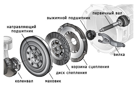
The presence of a clutch on cars contributes to the possibility of shifting gears. The UAZ Patriot SUV is also equipped with an indispensable clutch, which consists of two discs, one of which is the master and the second is the slave. The driven clutch disc transmits torque to the gearbox when it is connected to the drive disc. The driving disk has direct hard contact with the vehicle crankshaft. But in order to separate these two discs, the design of each clutch system provides important element called the release bearing. In this material, we will consider its purpose and design, as well as methods for determining a malfunction and the principle of its replacement on an UAZ Patriot SUV.
In the design of the clutch, the release element occupies an important place, since it is with its help that the driven and master clutch discs are separated, which allows you to shift gears or turn on neutral speed. Its breakdown is a critical factor, which entails the impossibility of operating the car.
The release bearing on a UAZ Patriot car has the simplest design and is a regular ball element that performs quite important function. Today, hydraulically controlled clutch bearings are known, which improves the functionality of this unit, but ordinary products are installed on the UAZ Patriot, which will make it possible to reduce the cost of modifying a car.
The cost of a clutch release for a UAZ Patriot usually ranges from 800 to 1200 rubles, which depends on the manufacturer. But it makes no sense to pay more if the part produced by the Ulyanovsk plant has proven itself on the good side. Of course, the service life of the product will not be 100 thousand kilometers, but the bearing passes up to 30-40 thousand kilometers.
The principle of operation of the product is quite simple and it consists in the possibility of ensuring the moment of connection and separation of the clutch discs, which occurs at the moment the driver presses the pedal. The driven disk is pressed against the flywheel due to the pressure plate, which actually contributes to the engagement of the clutch. The pressure plate is affected by pressure from the diaphragm spring, and its inner petals are affected by release bearing. This element is driven by the clutch fork.
During operation, this element fails, which requires its replacement. But first, let's define the signs that indicate the failure of the release bearing on the UAZ Patriot.
Symptoms
The main symptom of a malfunction of this element is a characteristic knock when you press the clutch pedal. In the case when this knock occurs during the summer periods, then this is a 100% guarantee of the subsequent replacement of the bearing. IN winter periods knocking can be caused due to changes in the size of the element itself. When heated, the knock should disappear.
The main reason for failure this device is the effect of uneven loads at the moment the clutch is depressed. In this case, it is not recommended to move in a car with the clutch pressed for a long time at speed, because in this case the need to replace it will accelerate. The service life of the device depends on the nature of the operation of the car, so if you use the clutch incorrectly, then in the near future you cannot avoid the need to replace the release.
Replacement
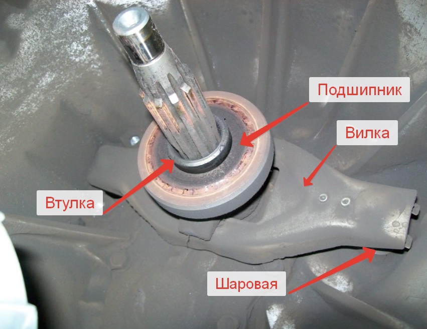
The diagram below shows the release bearing of the UAZ Patriot SUV, which shows its location on the guide sleeve 4. Number 2 indicates the clutch release fork, which rests on a ball joint screwed into the crankcase of the device.
To dismantle the product, you will need to perform the following steps:
After that, the removed parts are installed in the reverse order of removal.
This completes the replacement of the release bearing on the UAZ Patriot SUV and, as you can see, there is nothing difficult about it. The most difficult thing is the dismantling of the gearbox, but you can learn more about this from the corresponding section of this site. Monitor the condition of this device so that at one moment it does not let you down on the road.
How often does your Patriot break down?
Poll Options are limited because JavaScript is disabled in your browser.
0:7 1:514
Beginning to "slip" clutch UAZ Hunter - when hard pressing on the gas pedal in third gear, the engine rapidly gained momentum, and only after a few seconds the car began to accelerate. In first and second gears, the acceleration dynamics remained the same. This unpleasant moment made me nervous when performing the "overtaking" maneuver.
1:1151Work with the removal of the gearbox and transfer case includes draining the oil from these units, so it is recommended to do this within 15 minutes after the trip, until it has cooled down and is relatively liquid.
1:1498So we drive the car into the "pit", take off the negative terminal from the battery, drain the slurry from the gearbox and gearbox, and only then we begin preparatory work to dismantle the gearbox and gearbox.
1:1815
Drain the oil
2:28So, remove the front passenger seat, then remove the carpet from the passenger compartment. In my UAZ, noise insulation was glued under the carpet. Shumka was done by the previous owner.
2:339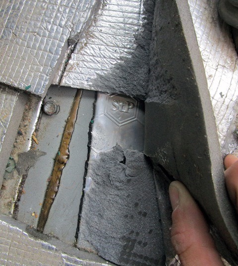
How not to do soundproofing in UAZ Hunter
3:931Under the noise, a factory layer of bituminous coating was found, which, without special work pulled away from the metal. There is no need to dream of any floor painting by the manufacturer - only a gray primer. As expected, the water made its way under the layers described above and began to rust. To my great joy, there are no serious pockets of rust, no holes were found in the floor. But still, the rust looks very unpleasant.
3:1693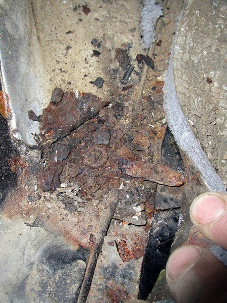
One of the turtle mounting bolts
4:65In the nearest plans it is necessary to include processing and painting of the floor. Carpet and Shumkov in the car will never be allowed again.
And now we continue to prepare for the removal of the gearbox.
We remove the anthers from the gearshift levers and transfer cases, then unscrew the levers themselves. Now we need to remove the "turtle", which consists of two halves fastened to each other and screwed to the floor with SEVENTEEN bolts (11 M6x20 bolts and 6 M6x16 bolts). We gave the first praise to the designers of the Ulyanovsk plant when we tried to unscrew these bolts. The fact is that the bolts are screwed into special nuts square-shaped, which are nested in limiters welded on the "street" side of the floor. Water and dirt get into threaded connection making it nearly indestructible.
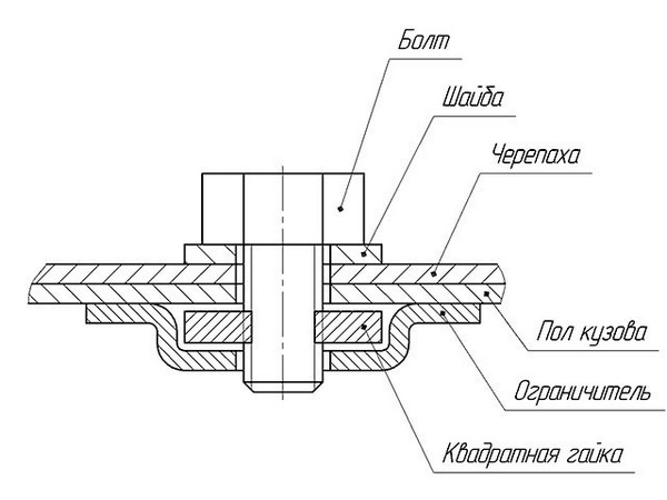
Tortoise mount UAZ Hunter
5:1975As a result, it turned out to unscrew only half of the bolts. The second half of the bolts either had their heads torn off, or the nut began to scroll in the limiter. I had to use a drill. After removing the turtle, we see the checkpoint and transfer case:
5:2407
View of the Dymos checkpoint from inside the car
6:573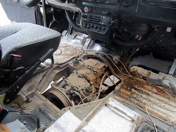
General view of the tragedy of my Hunter
7:1149Disconnect the light switch wiring harness reversing, speed sensor block. Remove both cardan shafts. Disconnect the cable parking brake(handbrake).
Loosen the four screws and remove transfer case. This is just a small warm-up on moving weights in space, it will be more fun later on.
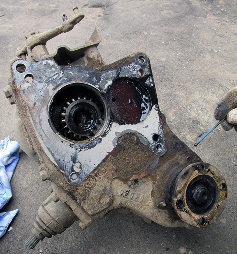
Razdatka
8:19After unscrewing the two bolts, remove the clutch slave cylinder. Carefully! The tappet may pop out of the working cylinder. We take the cylinder to the side so that it does not interfere. Loosen clutch slave cylinder
8:379From the starter, unscrew the power terminal of the traction relay and the "plus" terminal. Using the "trained hands of a proctologist" we unscrew the two starter mounting bolts (Holes No. 1 and No. 2 in photo 16). We remove the starter. It was not possible to completely remove the upper starter mounting bolt - it rests against the body (Hole No. 1 in photo 16). If the car is lifted with body-frame spacers, then the removal of the starter and gearbox is greatly facilitated. Let me remind you that I did not lift the body, I am not going to do it.
8:1217Now let's deal with the "pants" - the exhaust pipe of the muffler. If the pants are not unscrewed from exhaust manifold, then the process of removing the gearbox will become much more complicated. True, "taking off your pants" is also not very easy.
First, unscrew the clamping bar. There is only one bolt, but it is most likely zahryas))). I have it lubricated with graphite, so there were no problems.
The downpipe of the muffler (pants), or rather TWO parallel pipes, are attached to the manifold with eight copper nuts screwed onto the four studs of the manifold, two nuts per stud. Three pairs of nuts are unscrewed without problems, but it is very problematic to crawl up to the fourth pair with a tool. More precisely, it’s easy to unscrew, but to twist it back is hemorrhoids. We are saved by a good set of tools, from which such a stray is assembled:

Everything would be much easier if the gap between the pipes of the pants was a little wider ... Again, praise to the designers of the Ulyanovsk plant.
9:727
Garage gas stove
10:1295Holding the bolts from turning, unscrew the two nuts securing the bracket downpipe muffler (Holes No. 3 and No. 4 in photo 16). We remove the bracket. We unscrew the nut of the lower bolt securing the gearbox to the engine (Hole No. 5 in photo 16). The gearbox mounting bolts have different lengths, so we mark each bolt that is removed, marking its position on a piece of paper. We attach counter nuts and washers to the corresponding bolts.
10:2070
Each bolt has its place and serial number. (Here the numbers do not match the numbers in photo 16).
11:679We jack up the checkpoint. We are trying to remove the cross member of the frame on which the box lies. The gearbox cushion bolt could not be unscrewed, so they simply unscrewed the four bolts with nuts securing the cross member to the frame.
11:1039We unscrewed the four bolts securing the stabilizer to the frame, since it (the stabilizer) will interfere with the installation of the box after the clutch is installed.
11:1300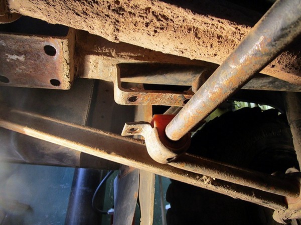
Unscrew the stabilizer to the frame
12:1887Now unscrew the remaining gearbox mounting bolts. We unscrew the two bolts on the right side in the direction of the car (Holes No. 6 and No. 7 in photo 16). And three bolts on the left side (Holes #8, #9 and #10 in photo 16). Access to bolts No. 7, No. 9, No. 10 greatly complicates the body floor stiffener.
12:2404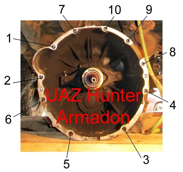
Photo 16. Location of mounting holes in the checkpoint Dymos UAZ hunter
13:621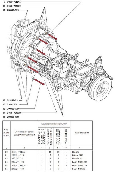
List of fasteners for docking the Dymos gearbox with the engine. The four bolts on the right side are not shown.
14:1303To facilitate access, you can carefully adjust the position of the gearbox with a jack. On a lifted body, access to the bolts is facilitated at times. Before unscrewing the last bolt, the gearbox was wrapped several times with a rope, the ends of which were tied to a crowbar lying in the car. This is a precautionary measure to prevent heavy objects from falling on our heads.
When all the bolts are finally unscrewed, we proceed to the final part of the orgy. Two people get into the cab, where they hold the box with a rope, one person in the "pit" undocks the gearbox and engine using a large slotted screwdriver and a mount.
...Across the span of the garage cooperative, the echo carries fragments of Russian obscenities...
14:137Next, the box is moved to a pre-prepared place - it is enough to take the box away from the engine by 50 cm and lay it on the boards across the pit. The main thing is that there is free access to the clutch basket, and the gearbox lies securely on the supports.
14:555Having rested after strength exercises with the gearbox, we begin to deal directly with the replacement of the clutch.
14:737For clarity and understanding of the process, I post a picture found on the vast expanses of the Internet.
14:932
Figure 1. Clutch UAZ Hunter with Dymos gearbox
15:15041 - crankshaft flywheel
2 - driven disk
3 - pressure spring
4 - clutch crankcase booster
5 - front bearing gearbox input shaft
6 - input shaft
7 - torsional vibration damper
8 - clutch release bearing
9 - clutch release bearing fork
10 - clutch release cylinder
11 - air vent valve
12 - hose
13 - clutch housing
14 - fork support
15 - pressure plate
Another picture for clarity:
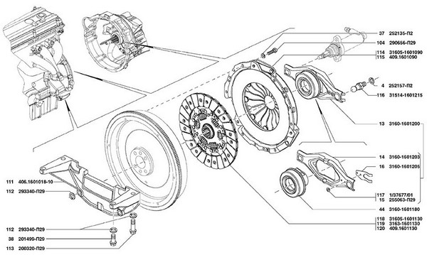
Figure 2. Picture from the UAZ Hunter parts catalog
16:592For correct installation new clutch, we need a special mandrel to center the driven disk. It can be purchased at the store, machined from improvised materials, or you can use the old gearbox input shaft (the gear must be cut off).
For self-manufacturing mandrels, you can read the corresponding topic on Uazbook and use the drawing with dimensions.
We used a mandrel from some other car, simply wrapping tape around it until we got the required diameters. I can’t vouch for the accuracy of the dimensions in figure No. 3 (the dimensions are taken from a sketch on Uazbuk).
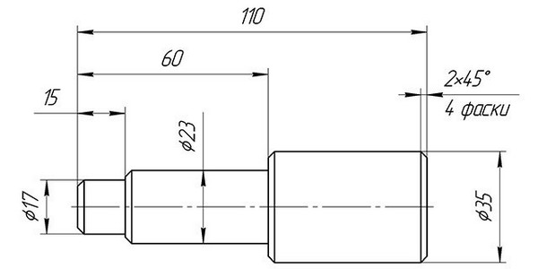
Figure 3. Mandrel for centering the UAZ Hunter clutch disc (Dymos gearbox)
17:142So, first we remove the old pressure and driven discs. To do this, while holding the flywheel from turning, we unscrew the six M8x30 bolts securing the clutch pressure plate casing to the flywheel. Carefully remove, trying not to drop the driven disk.
We carefully look at the removed parts:

Driven clutch disc
18:1215
Marking on the driven disk
19:1777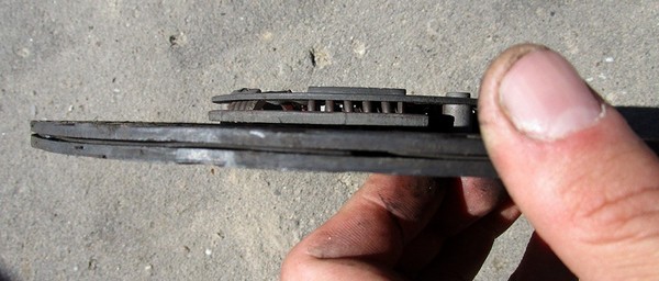
Clutch disc wear
20:60We see tint colors on the driven disk. Burnt…
By the way, on the disk we see the manufacturer's marking "LUK". This clutch was installed on the conveyor of the Ulyanovsk plant.
On the working surface of the pressure plate we see traces of overheating.

Clutch pressure plate
21:1049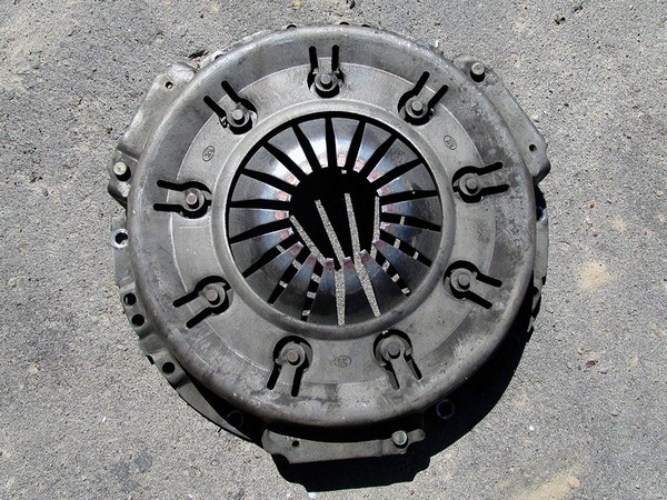
Clutch pressure plate. View from the side of the petals
22:1651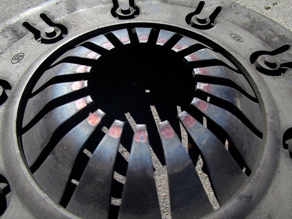
Clutch pressure plate. Petal wear
23:78Since we are so deep into the bottomless repair pit, let's try to minimize the likelihood of falling here in the near future. To do this, we need to inspect all components and parts for wear and, if necessary, replace them with new ones.
Here is what the UAZ Hunter Repair and Maintenance Primer recommends to us:
Inspection of parts and assemblies for wear:
1. If an oil leak is detected from the flywheel side, then we get on hemorrhoids with the replacement of the crankshaft rear oil seal and, for one thing, we change the gearbox input shaft toe bearing.
2. If there are traces of oil on the inner surface of the clutch bell, then we run to the store for the gearbox input shaft oil seal.
3. Checking the front thrust bearing gearbox input shaft for free rotation and lack of backlash. The bearing is broken - we put a new one, along with the oil seal.
4. We carefully study the working surface of the flywheel for the absence of scuffs, swelling, burns and irregularities. If the work surface is damaged, then we have two options:
a) we run to the turner, carefully grind the entire working surface of the flywheel, but not more than 1 mm (surface roughness should not be lower than Ra< 1,0).
b) buy a new flywheel, oil seal, bearing.
5. We inspect the splined end of the gearbox input shaft for damage. In the presence of damage, we change the input shaft, oil seal, bearing.
6. Is the clutch release fork deformed? Prepare the loot for a new one!
In our case, everything was dry and smooth. No backlash, scoring, beating or other swelling was found.
23:180
flywheel working surface
24:745It's time to get a new clutch out of the package. Remind me what I bought Clutch "TAYA" assembly reinforced (set of survival bearings n / o "TROFI").
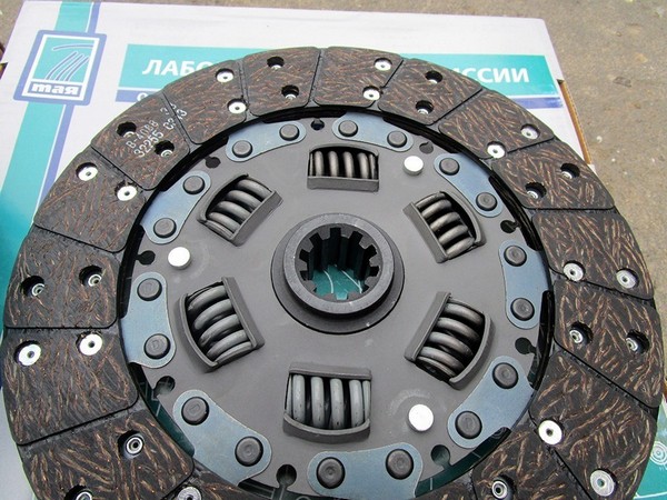
24:990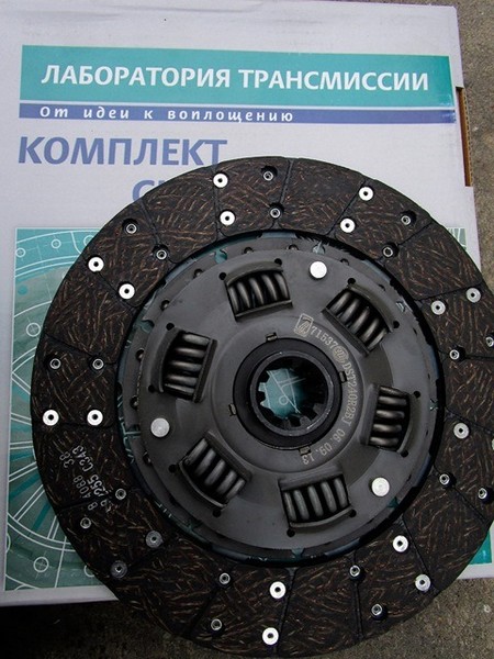
Clutch disc TAYA
25:1550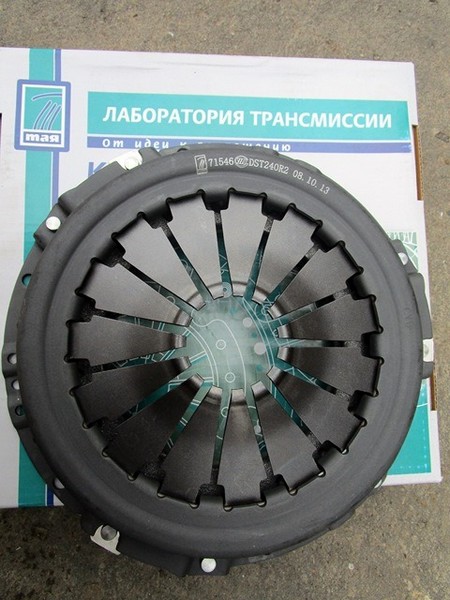
Clutch pressure plate TAYA
26:54
TAYA clutch pressure plate. View from the side of the petals
27:661
TAYA clutch pressure plate. Side view
28:1242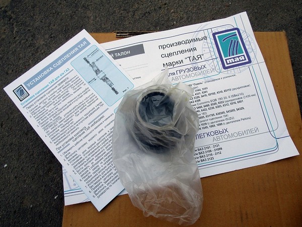
Release bearing TAYA
29:1795Before installing the clutch, we check the ease of movement of the driven disk along the splines of the gearbox input shaft. The disc should move without jamming.
Now we need to determine which side to the flywheel to install the clutch disc.
"LUK" took care of the client by writing "Flywheel side" on one side of the driven disk. "Flywheel" - flywheel, "side" - side. This means that this side of the driven disk is pressed against the flywheel. Everything is simple and clear.
The Transmission Laboratory "TAYA" did not take care to put such an inscription on the driven disk, therefore, for the correct installation of the driven disk, we carefully look at the drawing in the instructions.
This side of the driven disk is pressed against the flywheel
30:609Using a mandrel, we put the driven disk on the flywheel, then install the pressure disk and bait six bolts by hand. Finally tighten the bolts evenly, half a turn, moving from bolt to bolt clockwise. The tightening torque of the clutch pressure plate fastening bolts (according to the Primer): 2.0 - 2.5 kgf * m.
We extract the mandrel.
We remove the old release bearing (it comes complete with a clutch). To do this, we slightly move forward (from the gearbox) the bearing together with the clutch release fork. Carefully remove the fork from the ball joint. We remove the old clutch assembly from the fork with the release bearing. We examine the fork for wear and deformation. We leave the “bouncy” fork, we change the “tired” one for a new one. We install a new clutch assembly with the release bearing in the fork.
Before installing the node in its place, it is necessary to apply a small layer grease on the guide bushing of the gearbox input shaft bearing cover, on inner surface release bearing clutch and at the contact points of the fork with the ball bearing and the rod of the clutch slave cylinder.
After lubrication, put the plug in its place.

Clutch release fork with release bearing installed
31:626You can start docking the engine with the gearbox. We lubricate the splines of the input shaft with Litol-24. Two fighters in the cab of the car are holding the gearbox on the ropes, one fighter under the car is trying to put the gearbox input shaft into the flywheel and align the mounting holes in the clutch housing with the pins on the engine. If the driven disk is centered well, then this operation is fast. Further assembly is carried out in the reverse order of disassembly.
31:1431Other recommendations:
Do not forget to smear the mating surfaces of the gearbox and gearbox with sealant. We tighten the bolts of the gearbox to the engine and the bolts of the gearbox to the gearbox evenly, in a turn of the key, moving from bolt to bolt clockwise. Tightening torque (according to the Primer): 4.0 - 5.6 kgf * m.
When installing the "pants" do not forget to put a gasket. If the old gasket does not inspire confidence, we change it to a new one.
Tightening torque for flange bolts and nuts cardan shaft(according to the Primer): 3.2 - 4.0 kgf * m. Do not forget that after a couple of days it is worth checking the tightness of the bolts and nuts of the cardan shafts.
After installing all the components and parts in their places (except for the "turtle"), we check if we have any extra bolts, nuts and other brackets.
Pour oil into the gearbox and gearbox using a special syringe with a hose. Oil is filled up to the level of the oil filler hole. It is convenient to fill the oil before installing the "turtle", directly from the passenger compartment. Drain plugs must be tightened, copper rings on the plugs are not loved. Choose the brand of oil based on your financial opportunities and religious beliefs. Without installing the "turtle", we leave the garage for a test run, which revealed a slight slip of the clutch. By adjusting the length of the rod of the clutch slave cylinder, we achieve a normal setting without slipping. In this case, the clutch should not be "early" or "late", i.e. "Seizing" should occur in the middle of the clutch pedal travel.
The final chord of the second act can be done by bleeding the clutch with changing the fluid - a fresh "brake" is always better than the old one.
Designed for short-term disconnection of the gearbox from the engine at the moment of gear shifting. Additionally, it contributes smooth transmission torque from the engine to the transmission elements at the moment the car starts moving.
Mechanism device
On cars of this family, a single-disk dry-type clutch is used, with a device for damping rotational vibrations, which ensures the transfer of power moment from the motor to the box.
Assembled this mechanism The clutch consists of a driven disk with friction clutches and a pressure element, a housing and a shutdown drive mechanism. The casing is made of steel by stamping and is attached to the flywheel. Six springs are placed between it and the pressure element. The force of the springs contributes to the transmission of torque from the flywheel through the steel casing and the pressure mechanism directly to the UAZ clutch disc.
The slave is made of steel and has friction linings attached to it. Equipped with a torsional vibration damper. It consists of eight springs, a pair of friction washers and a base plate.
The mechanism moves splined shaft gearboxes. The process of disengaging the clutch occurs due to three levers, which are additionally equipped with adjusting bolts. The mechanism has a mechanical shutdown drive and consists of a pressure pedal, a pusher and two rods.
Clutch disc UAZ - dimensions and modifications
The design features of the clutch of this machine allow it to be used in a variety of road and climatic conditions. The mechanism has an increased motor resource and reliability. 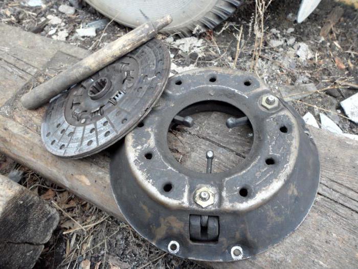 Due to the fact that various can be equipped with engines different modifications, then the clutch device on those may vary slightly.
Below are a few modifications:
- Complete set 417-1600010. It includes a pressure UAZ of the TM417-1601090 series, a driven element TM417-1601130 and a release bearing clutch. The size of the outer diameter of the friction surface is 240 mm, and the inner diameter is 150 mm. The thickness of the clutch is 3.5 mm, and the maximum torque is 21 kgf / m. This kit is installed on jeeps, cargo-passenger and trucks UAZ brands various modifications with a four-speed box.
- Slave 451-1601130. Quite often used and reliable UAZ clutch disc. Dimensions: outer diameter - 254 mm, friction clutch inner diameter - 150 mm, thickness - 3.5 mm. Maximum torque - 17 kgf / m. Designed for UAZ cars, which are operated in conditions high loads for clutch and transmission.
- TM417-1601130. The dimensions of the outer and inner diameters are 240 and 160 mm, respectively. What cars does this clutch disc fit on? UAZ-39625, 2206, 315194, 3741, 3303, 39094.
Breakdowns
As with other species Vehicle, UAZ clutch failure usually has similar signs of a malfunction of the mechanism.  Malfunctions that must be eliminated by removing the mechanism and replacing its parts: the presence of jerks at the time of movement from a place, excessive noise during the period of gear shifting. It is also slipping (incomplete engagement), sometimes the clutch leads (incomplete disengagement), there is a characteristic rattle in the area of \u200b\u200bthe basket.
How is the clutch disc replaced (including UAZ Patriot)? Dismantling it from the car is a rather laborious process and requires certain knowledge of the car device. Therefore, the work must be carried out by a knowledgeable person.
Required tool
To carry out repair operations, you will need: 12, a powerful screwdriver, a metal mandrel. 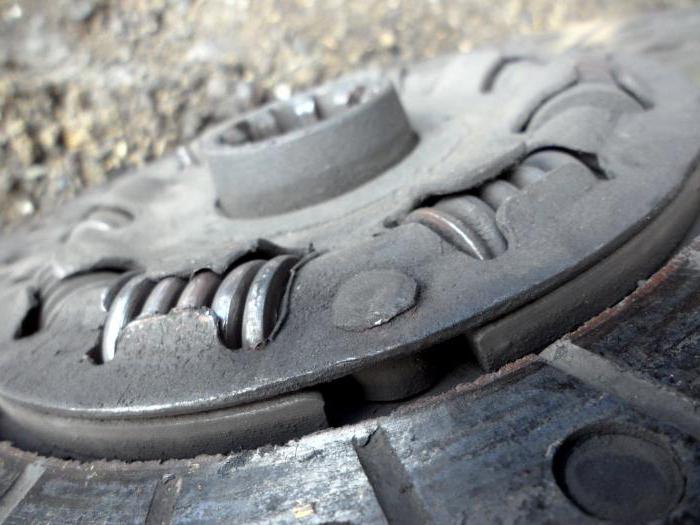 The latter is necessary in order to center the UAZ clutch disc driven. It also needs a little assembly.
Dismantling process
After the car is set to viewing hole and securely immobilized, it is necessary to remove the gearbox with clutch housing.
The release bearing assembly with the fork is removed by moving it forward along the guide. The thrust one is pressed into the clutch and is mounted on the sleeve with engagement in the fork of the mechanism. The latter rests against a ball joint fixed to the clutch housing. After removing the bearing with the coupling, inspect the fork for possible wear and deformation.
Then we proceed to dismantle the release disk. To begin with, we install a centering mandrel to prevent the driven element from falling out. We hold the flywheel so that it does not turn, and unscrew the six bolts in the casing of the pressure element that attach it to the flywheel. After that, you can remove the driven and clutch release plate.
UAZ - checking the condition of parts
We inspect the slave for damage and wear. Cracks, chips and damage to the disc elements are unacceptable. First, let's look at the clutches. When the lining rivets are recessed in the body by less than two tenths of a millimeter, the rivets are loosened, then such an element is unsuitable for further use. The UAZ clutch disc, and in particular its damper springs, must not have free play, breaks and chips. If at least one spring is defective, then the disc must be replaced.
We pass to the pressure mechanism. It is unacceptable to loosen the connecting rivets of the disk elements, and if this fact exists, then the part is unusable. The diaphragm spring must not be cracked, and the place of contact of the spring with the release bearing must be even and not have more than three tenths of a millimeter of wear. On the working plane of the flywheel and the plate of the release disk there should be no burrs, deep scratches, potholes and traces of overheating. If the elements of the clutch mechanism have the above defects, they must be replaced with new ones.
Installation of a new mechanism
The installation of the clutch disc (UAZ "Patriot" is no exception) is carried out after certain preparatory work. To begin with, we look for the driven element to move freely along the splined section of the gearbox input shaft. It should not have jamming and play during axial movement. The reason for this discrepancy may be the development on the shaft, which in this case also changes. The paws of the release levers of the pressure element must be in the same plane, if necessary, we adjust them.
We apply a new clutch disc (UAZ "Patriot" diesel 2.3) assembled with a clutch release to the flywheel. Using a mandrel or an unsuitable shaft, we center the driven element and proceed to fix the release mechanism. After all six bolts are securely screwed in, you can remove the mandrel. It is important to note that you need to tighten the bolts in a certain way: diagonally, with a moment of 1.4-1.8 kgf / m.
Immediately before mounting on the engine of the gearbox complete with clutch cover, it is necessary to lubricate the guide sleeve of the release bearing and inner part couplings.
Next, we engage the clutch with the drive fork. 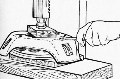 We put the locking plate on the stop, and then we put the fork paired with the clutch on the cover sleeve. After the work done, we put the box and check the operation of the clutch.
Bleeding the drive
If the replacement of the clutch disc (including the UAZ Patriot) is carried out correctly, all the elements of the mechanism comply with the norm, and the mechanism does not work, then the reason may be in the drive itself. The process of pumping the system must be carried out with a partner.
Directly the process
Remove the cap from the fitting for pumping the hydraulic cylinder. Then we put a transparent rubber tube on the fitting. We place its second end in a container, previously half filled with liquid. Then one person depresses the clutch pedal four or five times and holds it in the depressed position. The partner, using an eight-key, unscrews the fitting about half a turn. At this point, the pedal will fail, and liquid with air bubbles will flow from the fitting. At the moment when the pedal touches the stop and the flow of fluid stops, tighten the fitting and repeat the bleeding procedure. This must be done until the flow of liquid with air formations stops from the fitting. During pumping the system, you need to monitor the fluid level in the expander so as not to re-air the actuator. The same problem can arise if you change the UAZ-452 clutch disc, since the entire clutch mechanism of cars is the same.
Periodic maintenance
All maintenance consists in the need to check the reliable fastening of the mechanism casing and the wear of the friction parts of the disc.
The spent clutch resource can be determined by taking into account the distance between the release element and the flywheel at the moment the clutch is engaged. 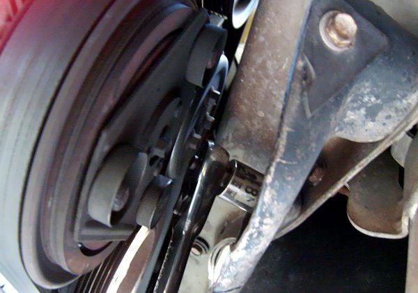 In this case, the distance indicator should not be less than six millimeters.
It is necessary to check the clutch disc (UAZ "Hunter", "Patriot", UAZ-3303 including) every eighty thousand kilometers when normal operation and through fifty thousand in extreme conditions.
Slave disk repair
Often the element cannot be repaired and it is completely replaced with a new one. But still it can be restored.
We raise the tendril of the vibration damper spring a little higher than the plane of the damper washer and turn the spring by forty-five degrees. Next, remove the spring, thermal insulation washer and damper washer. We drill three thrust fingers with a drill and dismantle six damper springs. We also drill out the fastening rivets of the friction parts and the rivets holding the spring-loaded plates.  After the work done, new parts can be mounted on the UAZ-469 clutch disc.
Installation takes place in the reverse order of disassembly - we attach spring plates with rivets. On top of the aluminum rivets we fasten the friction parts. We install the damper plate on the hub with a set of springs and rivet the thrust fingers.  On the rectangular hub part we put on the washer of the vibration damper, thermal insulation and The landing of the spring must be done until it coincides with the groove on the hub, and then turn it 45 degrees to fix it.
Conclusion
Repairing a UAZ car (replacing a clutch disc) is a difficult process, but quite doable even at home. Moreover, these machines are designed in such a way that anyone, even a novice driver, can deal with them.
Send your good work in the knowledge base is simple. Use the form below
Students, graduate students, young scientists who use the knowledge base in their studies and work will be very grateful to you.
2.1 Purpose of the clutch of the UAZ 469 car
The clutch is designed to transmit torque from the flywheel of the crankshaft of the engine to the input shaft of the gearbox. At the same time, the clutch allows the driver to briefly interrupt the transmission of torque, separating the engine from the transmission, and then smoothly connect them.
The clutch consists of: a drive and the clutch mechanism itself.
2.2 Clutch devicecar UAZ 469
The clutch is friction clutch, in which the transmission of torque occurs due to the force of friction. It allows you to briefly disconnect the rotation of the crankshaft of the engine from the rotation of the input shaft of the gearbox and again smoothly connect them.
On modern models cars a dry single-plate clutch is installed with one chain
central diaphragm spring 10 in the form of a truncated cone Spring
Diaphragm Clutch:
/--stud, 2-clutch cover, 3-link, 4-support ring, 5-heel, 6-release bearing, 7-bearing cage, 8-oil seal, 9-tie pin, 10 -- diaphragm spring, "11 -- pressure plate, 12 -- driven disc, 13 -- crankcase, 14. -- flywheel, 15 -- shield, 116 -- transmission drive shaft, / 7 -- damper disc spring stamped from sheet spring steel 0.9 mm thick.
The radially arranged 18 spring petals not only create elastic elements, but at the same time they are release levers.
Structurally, the clutch with a diaphragm spring is made in the form of two non-separable units. One consists of a pressure plate 11 assembled with a diaphragm spring and a casing 2, the other of a driven disk 12 with a torsional vibration damper. The clutch is enclosed in the crankcase 13, which is attached to the engine block. To disengage the clutch, a sliding clutch with a bearing is used, to which the force is transmitted from the control pedal through a hydraulic or cable drive. Torque from the engine! through the flywheel and pressure! disk 11 is transmitted to the driven disk 12, and from it through the damper springs 17, the hub of the driven disk and the spline connection - to the drive shaft of the gearbox 16.
When you press the pedal, the clutch, moving along with the bearing towards the flywheel, presses through the thrust flange, to which the friction ring is glued, onto the petals of the diaphragm spring. In this case, the outer edge of the spring, moving in the opposite direction, moves away from the annular protrusion on the pressure plate and through the clamps takes it away from the driven disc, releasing the latter from the engine torque.
1 - pressure plate, 2 - clutch housing, 3 - flywheel, 4 - clutch lever, 5 - driven disk, 6, 7 - springs, 8 - release, 9 - clutch release, 10 -- transmission drive shaft, 11 - release spring, 12 - clutch release fork, 13 - support fork, 14 - clutch cover.
On GAZ-24, VAZ and ZAZ-968 cars, a dry single-plate clutch with peripheral pressure springs is installed. The casing of springs 6 and 7 is screwed to the flywheel. When the clutch is engaged, the pressure plate, under the action of the springs, presses against the end surface of the flywheel, the driven disk 5, which sits on the splines of the drive shaft 10 of the gearbox. 4.
Friction linings made of a material with a high coefficient of friction are riveted to the driven disk.
Damper springs are used to quickly dampen the torsional vibrations transmitted to the clutch from the engine crankshaft.
Passenger cars have a hydraulic or mechanical cable clutch release. master cylinder 2 hydraulic drive the clutch of the GAZ-3102 car is connected by a pipeline to the working cylinder 10. The plunger of the working cylinder through the pusher 9 acts on the clutch release fork interconnected with the pressure bearing.
At the mechanical cable drive when the clutch is released, when the pedal 10 is pressed, the cable acts on the lever 2, connected by means of an axis to the lever 11, which moves the release bearing 1.
Hydraulic clutch release:
/ -- pipeline, 2 -- master cylinder, 3 -- pedal spring, 4 -- clutch spring [bearing, 5 -- spherical bearing forks, 6 -- clutch release fork, 7 -- pull-back [spring, 8 --- pedal, 9 -- working cylinder pusher, 10 -- working cylinder
Clutch release cable drive:
1-release bearing, 2.9-levers, 3-splash cover, 4-adjusting sleeve, 5-locknut, 6-cable sheath, 7-body bulkhead, 8-cable, 10-pedal, 11-release bearing lever.
2.3 The principle of operation of the clutchcar UAZ 469
When you press the clutch pedal, the force of the driver's foot, through the rod and piston, is transmitted to the fluid, which, in turn, transfers pressure from the master cylinder piston to the working piston. Further, the rod of the working cylinder moves the clutch release fork and the thrust bearing, which transmits the force to the clutch mechanism. When the driver releases the pedal, then under the influence of the return springs, all parts of the drive will take their original positions.
clutch mechanism
The clutch mechanism is a device in which torque is transmitted due to the work of friction forces. It is the clutch mechanism that allows you to briefly disconnect the engine and gearbox, and then smoothly connect them again. The elements of the mechanism are enclosed in the clutch housing, which is attached to the engine crankcase.
The clutch mechanism consists of (see Fig. 1):
crankcase and casing,
drive disk (which is the engine crankshaft flywheel),
pressure plate with springs
driven disc with special wear-resistant pads.
The driven disk, connected to the input shaft of the gearbox, is constantly pressed against the flywheel by a pressure disk under the influence of very strong springs. Due to the huge frictional forces between the flywheel, the driven and pressure plates, all this together, as a whole, rotates when the engine is running. But this is only when the driver does not touch the clutch pedal, regardless of whether his car is driving or standing still.
And to start the movement of the machine, it is necessary to press the driven disk connected to the drive wheels (through the input shaft of the gearbox and other components of the transmission) to the rotating flywheel, that is, to engage the clutch (Fig. 2), bring it into a state of monolith. And this is a difficult task because angular velocity flywheel rotation is 20 - 25 revolutions per second, and the speed of rotation of the drive wheels is zero.
Rice. 2 Clutch engaged
At the first stage of work on engaging the clutch, we release the pedal, that is, we enable the springs of the pressure plate to bring the driven disc to the flywheel until they lightly touch. Due to the forces of friction, the disk, slipping for some time relative to the flywheel, will also begin to rotate, and your car will slowly crawl.
At the second stage, we hold the driven disk from any movement, that is, for two to three seconds we hold the clutch pedal in the middle position so that the speed of rotation of the flywheel and disk equalizes. The machine at the same time slightly increases the speed of movement.
At the third stage, the flywheel, together with the pressure and driven disks, already rotate together without slipping and at the same speed, 100% transmitting torque to the gearbox and then to the driving wheels of the car. This corresponds to the state of the clutch mechanism - on, the car is moving. Now it remains only to completely release the clutch pedal and remove your foot from it. If, at the beginning of the movement, the clutch pedal is abruptly thrown, the car will “jump” forward, and the engine will stall. In the worst case, something else will break, since at this moment a strong shock wave arises, which greatly increases the load on all engine parts and transmission units.
To disengage the clutch, the driver presses the pedal, while the pressure plate moves away from the flywheel and releases the driven disc, interrupting the transmission of torque from the engine to the gearbox (Fig. 3). Press the clutch pedal should be fast enough, but not abrupt, calm movement until the end of the pedal stroke.
Rice. 3 Clutch disengaged
2.4. Main malfunctionsti clutch car UAZ 469
Clutch slips
If during the movement of the car a specific smell (burning) of the friction linings of the clutch occurs, there is a slow acceleration of the car, a decrease in speed or a slow climb, then the reason for this is the slipping of the clutch, i.e. the clutch is not fully engaged. To finally make sure that the clutch is slipping, it is necessary to tighten the parking brake handle with the engine running. brake system to failure and engage transmission. Then, while gently depressing the throttle control pedal, slowly release the clutch pedal. If, with the clutch pedal fully released and open throttle the engine stops, the clutch does not slip, but if the engine continues to run, the clutch slips.
To eliminate the causes of slipping of the clutch, it is necessary first of all to check and, if necessary, adjust the free play of the clutch pedal. If the clutch still slips during normal free play of the pedal, then you should contact the specialists at the service station. In the case when this is not possible, you can eliminate the causes of clutch slip yourself. To do this, it is necessary to unscrew the bolts 7 securing the casing 5 to the flywheel 8, having previously removed the gearbox. Then remove the clutch cover assembly with the pressure plate 6. This releases the driven disc 2 (with friction linings / and 3) of the clutch. In this case, it is necessary to carefully check by external inspection whether the functional
VAZ car clutch:
a - details of the mechanical part of the clutch;
b - hydraulic drive
clutch disengagement; 1 and 3 - friction linings; 2 -- driven disk;
4 --rivet
5-- casing; 6 - pressure plate; 7 - bolts;
8-- flywheel; 9 - bearing;
10 - tank; //-- hose; 12-- the main cylinder of the actuation drive
clutch; 13-- inlet tube;
14-- working cylinder; 15 - pusher; 16-- lining spring / and 3 driven disk, is there any increased wear on them.
To eliminate oiling of friction linings, thoroughly rinse the linings with gasoline (kerosene), wipe them dry and clean them with fine sandpaper. Replace a heavily oiled driven disk with a new one complete with friction linings and also eliminate the causes of oiling. When the friction linings of the driven disc are worn, the clutch also slips, as the free play of the clutch pedal decreases.
With a slight wear of the lining of the driven disk (the lining is completely worn out if the distance between the rivets 4 and the working surfaces is less than 0.2 mm), slipping of the clutch can be eliminated by adjusting the free play, and in case of high wear, only by replacing the driven disk assembly with worn linings. Friction linings should also be replaced if cracks are found on their surfaces, if they are unevenly worn (one-sided scoring) and burnt out.
It is advisable to check the condition of the friction surfaces of the flywheel, clutch cover, pressure plate at the service station, since special tools and instruments are required.
Clutch slippage may occur due to swelling of the rubber sealing (cuffs) rings 5 and the rubber annular floating valve 7 of the master cylinder piston 6 / and clogging of the compensation hole 2 or swelling of the rubber sealing rings 12 and 14 of the working cylinder 9 of the clutch release drive.
The causes of swelling of rubber parts are the use of brake fluid of poor quality or inappropriate composition, or the ingress of gasoline, kerosene, mineral oil into the working fluid.
Main (a) and working (b) clutch release cylinders:
/-- housing of the main cylinder of the clutch engagement drive; 2 - compensation hole; 3-- rubber protective cap; 4 and 17 -- retaining rings; 5 - sealing ring; 6-- piston; 7--annular floating piston valve; 8 and / 5 - springs; 9-- the body of the working cylinder of the clutch actuator; 10-- protective cap; I-- pusher; 12 and 14 - rubber sealing rings; /3 - piston; 16-- oil washer.
To eliminate this malfunction, it is necessary to remove the main and working cylinders of the clutch drive, disassemble them (see the section “Clutch drives”), flush the entire hydraulic drive system with alcohol or fresh brake fluid, replace damaged rubber parts, clean the compensation hole with soft wire and fill it with brake fluid of the appropriate composition and quality.
Clutch "leads"
When the clutch is not fully engaged, the car moves jerkily, gear shifting is difficult, since when the clutch release pedal is pressed, its disks do not completely diverge, and the transmission drive shaft continues to rotate. A common symptom of a clutch failure is also incomplete disengagement, i.e., the clutch “leads”.
The completeness of the clutch disengagement can be checked as follows. At a low engine speed, depress the clutch pedal to failure, and if the first gear is switched on silently, then the clutch is fully engaged. If, when turning on the first gear, a strong noise of the gears is heard and the gear does not turn on or turns on with difficulty, then the clutch “leads”. In this case, the free travel of the clutch pedal should be adjusted (see recommendations in the "Clutch Adjustment" section). If the free play of the clutch pedal is within the normal range, then air or a leak may have entered the hydraulic drive system. working fluid. In this case, it is necessary to remove air from the hydraulic drive of the system in the sequence indicated below.
Then, with the clutch pedal pressed all the way down, check the tightness of the pipeline, its connections and the working cylinder.
If leakage of the working fluid is detected, tighten the connection until the leak is eliminated, and replace the damaged parts of the clutch release hydraulic drive found. If, during the check, fluid leaks from the working cylinder are detected, it must be removed from the vehicle, having previously unscrewed the two screws securing its body 14, the supply pipe 13, the pusher 15 and the spring 16 and disassembled. To disassemble the working cylinder from its body 9, remove the protective cap 10, the pusher // and the piston 13. To replace the damaged rubber parts (sealing rings 12 and 14), it is also necessary to disassemble the piston 13 by removing the retaining ring 17, the washer 16 and the spring 15. Parts should be thoroughly washed with fresh brake fluid or alcohol.
In the absence of damage to the cylinder mirror and rubber parts, reassemble the working cylinder and check for leaks. If damage to rubber parts is found or there are shells and marks on the mirror of the working cylinder, replace these parts and install the working cylinder in place.
Leakage of the working fluid from the clutch hydraulic system can occur as a result of a violation of the tightness of the clutch master cylinder, due to damage to the internal sealing rings (cuffs), cylinder mirrors, or contamination of the working parts of the assembly. In this case, it is necessary to remove the master cylinder 12 of the clutch release drive by unscrewing the two nuts securing it to the pedal bracket and removing the hose // connecting the cylinder to the reservoir 10. To identify the cause of the leakage of the clutch release master cylinder, it should be disassembled sequence: remove the rubber protective cap 3 (see Fig. 36, a), retaining ring 4, piston 6, sealing ring 5, piston annular floating valve 7 and spring 8. Thoroughly flush all parts with brake fluid and carefully inspect their condition. In the absence of scratches, scuffs and shells on the mirror of the main cylinder, as well as with serviceable internal rubber rings, install the cylinder in place. If necessary, replace defective parts or master cylinder assembly.
If, after carrying out the described work, the clutch still "leads", then probable causes can be: non-simultaneous pressing of the clutch release bearing on the levers, warpage (skew) of the clutch driven disk or jamming of the driven disk hub on the splines of the gearbox input shaft. It is necessary to eliminate these malfunctions at the service station.
Hard engagement and clutch noise
A characteristic sign of a clutch malfunction is also its uneven engagement. This is evidenced by jerks and shocks in the transmission when starting the car, despite the smooth release of the clutch pedal.
To detect and eliminate the causes of abrupt engagement of the clutch, it is necessary to remove the clutch from the vehicle. At the same time, the condition of the driven disk with friction linings and pressure springs is checked and eliminated by the methods discussed earlier. The condition of the windows under the damper springs, the working surfaces of the flywheel and the pressure plate, the condition and relative position of the clutch release levers and the casing are recommended to be checked and eliminated by adjustment or repair with the replacement of worn or broken parts at the station Maintenance.
Sometimes clutch noise is heard when engaging or disengaging the clutch. To eliminate noise, check and, if necessary, restore the reliability of mounting the engine with the gearbox. In this case, the bolts securing the gearbox to the engine must be tightened to failure. Noise in the clutch may also be due to seizing or increased wear of the clutch release bearing 9. discovered bad bearing should be replaced with a new one. Noise in the clutch due to increased runout of the heel of the release levers, wear of the vibration damper parts and other reasons, it is recommended to check and eliminate it at the service station.
Relatively rarely, such malfunctions can occur in the clutch, such as the failure of the clutch pedal to return to its original position after removing the foot from it; an increase in the effort required to disengage the clutch, pedal trembling at the initial moment of disengaging the clutch, etc.
These malfunctions occur due to a breakdown or weakening of the clutch pedal release spring, jamming in the clutch joints or its drive, increased beating of the heel of the release levers.
These malfunctions are eliminated by replacing a broken release spring and other worn parts of the clutch actuator or by adjusting the position of the heel of the release levers.
Similar Documents
Purpose, device and principle of operation of the clutch of a VAZ-2110 car. Causes of possible clutch malfunctions, the procedure for its disassembly, repair and assembly. Organization of the locksmith's workplace. The process of replacing the friction linings of the clutch disc.
term paper, added 06/20/2012
The clutch device as the first transmission device, its purpose is to transmit torque from the engine crankshaft flywheel to the gearbox input shaft. Scheme of the hydraulic drive for disengaging the clutch and the clutch mechanism.
presentation, added 12/22/2013
The use of a clutch to transmit torque from the engine, its connection with the transmission. The main elements of the clutch car VAZ-2108: drive, driving and driven parts. The principle of operation and maintenance of a dry single-plate clutch.
term paper, added 02/10/2013
Technical specifications steering of the car VAZ-2121; safety assurance. Purpose, device and principle of operation of the clutch; the main symptoms of a malfunction, the detection and procedure for eliminating the causes of abrupt engagement of the clutch.
term paper, added 10/08/2011
Purpose and requirements for the clutch of the car. Analysis of its existing designs. Selection of basic clutch parameters. Calculation of the clutch shaft and the hub of the driven disk. Maintenance of the designed structure. Calculation of clutch wear.
term paper, added 03/07/2010
Clutch master cylinder. The main malfunctions of the clutch and their elimination. Checking the runout and editing the driven disk. Topping up the hydraulic drive system with fluid and bleeding. Applications and methods of gas welding.
thesis, added 01/21/2011
Vehicle maintenance and repair system. GAZ-3307 clutch device, its repair and maintenance. Possible clutch malfunctions, their causes and methods of elimination. Technological process repair of the clutch disc.
term paper, added 11/18/2014
Device, operation, maintenance of the clutch, possible faults and methods for their elimination. Lubrication of the clutch and flushing of the hydraulic drive system on the example of the clutch of KamAZ vehicles. Safety precautions and industrial sanitation.
thesis, added 04/23/2013
Calculation of friction linings (indicators of loading of clutch friction pairs, clutch safety factor values), parameters of clutch springs. Determination of the stroke of the pressure plate when the clutch is turned off, the force on the pedal, the parameters of the pneumatic booster.
term paper, added 12/23/2013
Causes of incomplete inclusion (slipping of the driven disks), incomplete disengagement and abrupt engagement of the vehicle's clutch. Holding diagnostic work, types of maintenance. Characteristics of the stand for disassembly, assembly and adjustment of clutches.