The switching relay and fuses of the main circuits of the electrical equipment are located in the block. On left-hand drive vehicles, the main fuse box is located in the engine compartment on the right-hand side, and on right-hand drive vehicles, on the left-hand side. On the cover of the block, the rated current of the fuses, the circuits they protect and the electrical equipment switched on through the relay are indicated. Fuses for individual sections of the electrical circuit are located in an additional block installed in the instrument panel. The fuse numbers are indicated on the unit body.
Main fuse and relay box (in the engine compartment): 1 - 100 A fuse for the battery circuit (BATTERY); 2 - 15 A fuse for the horn and brake signal circuits (HORN STOP); 3 - 10 A fuse for the alarm circuit (HAZARD); fuse for 30 A of the headlight block circuit (HEAD LIGHT); 5 - unused fuse sockets (reserve); 6 - 40 A fuse for the starter relay and ignition switch circuit (IG1); 7 - 40 A fuse for the power window circuit (POWER WINDOW); 8 - 7.5 A fuse for the interior lighting circuit (INTERIOR LIGHT); 9 - 15 A fuse for the ECU circuit of the engine control system (Fl Е / М); 10 - 7.5 A fuse for the reversing lamp circuit (BACK UP); 11 - 20 A fuse for rear window heating element circuit (RR DEFROSTER); 12 - 20 A fuse for central locking circuits and ventilation hatch electric drive (DR LOCK UNIT. ROOF); 13 - 10 A fuse for the air conditioner radiator fan circuit; 14 - 40 A fuse for the heater fan circuit; 15 - 20 A fuse for the electric fan circuit of the engine cooling system (COOLING FAN); 16 - turn-on relay (HEATER MOTOR RELAY); 17 - 40 A fuse for additional equipment circuits (HEATER MOTOR); 18 - relay for turning on the electric fan of the engine cooling system (COOLING FAN RELAY); 19 - relay for turning on the air conditioner (MG. CLUTCH RELAY); 20 - relay for turning on the air conditioner radiator fan (CONDENSER FAN RELAY)
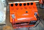
Additional mounting block for fuses and relays: 1 - pliers for removing fuses; 2 - fuses F23-F33; 3 - fuses F12-F22; 4 - fuses F 1 - F U; 5 - socket for installing a spare fuse; 6 - three slots for installing spare fuses
Fuse box and ABS relay (in the engine compartment): 1 - relay for turning on the ABS pump (PUMP MOTOR RELAY); 2 - 7.5 A fuse for the ABS electric pump circuit (MTR CHECK); 3 - 20 A fuse for the ABS electrical circuit (ABS + B); 4 - 40 A fuse for the ABS electric pump circuit (PUMP MOTOR)
Before replacing a fuse, it is necessary to determine and eliminate the cause of its blown. To avoid damage to electrical components, you must not install fuses rated for a higher current or replace them with self-made ones.
Check and replace 1. Disconnect the terminal of the wire from the negative terminal of the battery. 2. On cars with right-hand controls, to access the mounting block installed in the dashboard, open the coin drawer. Raising it slightly, we remove the lower part from engagement with the instrument panel. Moving the box down, we bring out its upper limiting ledge and remove the box. On cars with the left-hand arrangement of the controls, open the block cover.
The fuse box located in the dashboard contains tweezers for removing small plug-in fuses from their sockets. The amperage and the fuse circuits to be protected are indicated on the lid and back of the coin box.
3. To access the fuses and relays of the main mounting block, press on the two latches and open the block cover. 4. Squeeze the fuse case with tweezers and remove the fuse from the block. 5. A defective fuse is identified by a blown thread.
10. To replace the relay, remove it with your fingers. 5. A defective fuse is identified by a blown thread.
Sometimes the fuse thread remains intact, while its connection to the terminals inside the fuse is broken. It is impossible to visually identify such a malfunction. In this case, assess the condition of the fuse using an ohmmeter.
6. Install a new fuse of the appropriate rating. 7. Fuses built into rectangular cases (MAXFUSE / in the translated literature they are called "fusible links"), remove with your fingers or pliers. 8. To replace the high current fuse, use a Phillips screwdriver to unscrew the two screws of its fastening. 9. Remove the fuse from the mounting block.
When installing such a fuse, it must be securely fastened by tightening the fastening screws.
10. To replace the relay, remove it with your fingers.
You can make sure that the relay is faulty if you install another one in its place - a known good one.
11. Install a new relay of the same type. 12. At the end of the work, close the cover of the mounting block (or install the box for coins in the dashboard) and connect the battery.
| Additional block fuses and protected circuits | ||
| № | Current strength, A | Protected circuits |
| F1 | - | Reserve (heating elements for exterior mirrors, fog lights) |
| F2 | - | Reserve (headlight washer, outside mirror heating elements) |
| F3 | 10 | Rear window wiper and washer |
| F4 | 10 | Right headlight (high beam) |
| F5 | 10 | Left headlight (high beam) |
| F6 | 10 | Rear socket (in luggage compartment) |
| F7 | 20 | Power window regulator, rear left door |
| F8 | 20 | Power window regulator for the right rear door |
| F9 | - | Reserve (ignition coil) |
| F10 | 20 | Power window regulator for the front passenger door |
| F11 | 20 | Power window for driver's door |
| F12 | 7.5 | Direction indicators |
| F13 | 15 | Fuel pump |
| F14 | 7,5 | Reserve (cruise control unit) |
| F15 | 7,5 | Generator |
| F16 | 7,5 | ABS |
| F17 | 7,5 | Relay for switching on the air conditioner |
| F18 | 7,5 | Reserve (relay for turning on the side light) |
| F19 | 7,5 | Reversing light bulbs |
| F20 | 7,5 | Reserve (side light lamps) |
| F21 | 10 | Right headlight (low beam) |
| F22 | 10 | Left headlight (low beam) |
| F23 | 10 | SRS airbags |
| F24 | 7,5 | Power window relay |
| F25 | 7,5 | Control devices |
| F26 | 20 | Windshield wiper and washer |
| F27 | 10 | Front outlet |
| F28 | 10 | Radio tape recorder, clock |
| F29 | - | Reserve (rear fog lights) |
| F30 | 7,5 | Instrument lighting lamps |
| F31 | 7,5 | Starter relay |
| F32 | 7,5 | License plate lamps, tail lamps |
| F33 | 7,5 | Locking system |
The information is relevant for Honda CRV 1995, 1996, 1997, 1998, 1999, 2000, 2001 models.
INNER FUSE BOX
There are several fuse boxes in the vehicle.
The inner fuse box is located under the dash panel on the driver's side. A decal indicating the location of the fuses is located on the steering column.
(For versions with petrol engines) FIRST UNDERHOOD FUSE BOX

The engine compartment fuse box is located on the left in the rear of the engine compartment. To open the fuse box cover, press down on the tabs as shown.
(For versions with diesel engine) UNDERHOOD FUSE BOX

(For versions with petrol engines) SECOND UNDERHOOD FUSE BOX

Checking and replacing blown fuses
In the event of a failure of any device or device that is part of the electrical equipment of your car, you must first check the correctness of the fuses. Find the fuse that protects the failed device using the diagrams and tables on pages 517 and 518 (gasoline vehicles) and pages 519 and 520 (diesel vehicles) or the diagram on the fuse box. Check, first of all, the serviceability of the fuses of the failed electrical equipment, and then all other fuses. Replace the blown fuses and check the functioning of the failed vehicle devices.

1. Turn the ignition key to the LOCK (0) position. Check that the headlights and all other electrical consumers are off.
2. Remove the cover from the engine compartment fuse box. 
3. Visually check the serviceability of all large fuses, which are located in the engine compartment fuse box; a blown fuse is a symptom of a malfunction. To replace the fuse, remove the fastening screws with a Phillips screwdriver. 
4. Using tweezers stored under the cover of the inner fuse box, remove all the small fuses that are located in the engine compartment, as well as in the boxes that are in the passenger compartment, and check their serviceability. On vehicles with gasoline engines, the fuse removal tweezers are located at the rear of the cover of the first engine compartment fuse box. 
5. A defective fuse is indicated by a blown fuse link inside the fuse box. Replace the blown fuse with a spare one rated for the same or less rated current.
If you do not have spare fuses, and you cannot continue driving with faulty electrical equipment, we recommend that you temporarily replace the blown fuse with a good one (of the same or lower rating) by taking it from a different slot in the fuse box. Take the fuse for the circuit of the audio system or cigarette lighter or any other electrical device that can be painlessly dispensed with for a while.
If you replace a blown fuse with a fuse with a lower rating, the new fuse may blow immediately. This is not a sign of a malfunctioning electrical system in the vehicle. Install a new fuse with the required rating as soon as possible.
ATTENTION!
Replacing a blown fuse with a new one with a higher rated current significantly increases the likelihood of failure of the vehicle's electrical equipment due to overload. Therefore, if the required spare fuse is not available, install a fuse with a lower rated current than the one being replaced. 
6. If the spare fuse with the required rating is blown quickly, this indicates a serious electrical malfunction in the vehicle. Leave the blown fuse in the socket and contact a service station to check and repair the car's electrical equipment.
For petrol versions The spare fuses are located at the rear of the cover of the first engine compartment fuse box.
Removing the fuse that protects the audio system will automatically shut down the system. The next time you turn it on, the text “Enter CODE” appears on the display, which normally shows the frequency of the radio station. You must enter the code using the preset keys (see page 276).
On vehicles with a navigation system, to enter the code, touch the corresponding icon on the screen. If the system is locked, the clock settings will be reset. The time is set according to the procedure outlined in the audio section of this manual.
FIRST UNDERHOOD FUSE BOX

The location and completeness of the electrical fuses installed in the engine compartment depends on the vehicle modification. In some cases, you can use the fuse layout shown on the sticker. The following table provides a complete list of fuses for your vehicle.
FUSES
REPLACEMENT
See figure 57
The fuses are located on the fuse and relay panel in either the engine compartment or the passenger compartment. If one fuse blows, one component or one circuit will not work. A blown fuse is caused by excessive current consumption. By checking the condition of the fuse, you will understand what caused it to blow.
A fuse with traces of burning, melting of the plastic sheath or without traces of a wire, which once served as a conductor, indicates the presence of a direct short circuit. to the ground.
1. Remove the cover from the fuse or relay box.
2. Check the fuses and identify the faulty one.
3. Remove and discard the faulty one.
5. Insert a new fuse with the same current rating.
A WARNING
Do not exceed the rating of a blown fuse. If the replacement fuse also blows, troubleshoot the circuit and repair.
6. Check the operation of the “problem” component or circuit.
FUSE-LINKS
The fuse links are located in the relay box in the engine compartment. If one fuse blows out, the entire circuit or multiple circuits will not work.Rice. 57 Remove the cover, usually near the steering column, to gain access to the fuses.
Rice. 58 The fuses are located in the relay box in the engine compartment
REPLACEMENT
See figure 58
1. Remove the cover from the fuse and relay box.
2. Check the inserts and determine the faulty one.
3. Remove and discard the faulty one.
4. Check the contacts in the box and clean if corroded. If any pins are damaged, replace them.
5. Insert a new fuse with the same current rating.
A WARNING
Do not exceed the rating of the burned-out insert. If the replacement insert also burns out, find the fault in the circuit and fix it.
6. Check the operation of the “problem” circuit.
BREAKERS
REFITTING IN THE START POSITION AND / OR REPLACEMENT
The breakers are located inside the fuse panel. If the fault disappears, corrects, or the circuit cools to normal temperature, they are automatically reset.
FLASHING BREAKERS
REPLACEMENT
Flashing turn signal interrupter / alarm relay
See Figures 59-64
1. Grasp the flashing interrupter and remove it from the connector located at the top of the fuse panel.
2. Check the socket for corrosion or other signs of loose contact.
3. Installation is carried out in the reverse order of removal.
INNER FUSE BOX1
Current, A
Protects chains
1
Current, A
Protects chains1
Not used
21
10A
Low beam, right headlight2
-
Not used
22
10A
Low beam, left headlight3
10A
Wiper, rear window washer
23
10A
SRS24
7.5 A
Power window relay4
10A
High beam, right headlight
25
7.5 A
Measuring device5
10A
High beam, left headlight
26
20 A
Windscreen wiper, washer6
10A
Rear electrical outlet for accessories27
10A
Front power outlet for accessories7
20A
Power window, rear left door28
10A
Radio8
20 A
Power window, rear right door
29
Not used30
7.5 A
Meter indicator9
15A
Ignition coil10
20A
Power window, front passenger door
31
7.5 A
Starter signal32
7.5 A
License plate light, tail light11
20A
Power window, driver's front door33
7.5 A
Locking system12
7.5 A
Turn Signal Lights
34
7.5 A
Spare fuse13
15A
Fuel pump
35
10A
Spare fuse14
7.5 A
Cruise control
36
15A
Spare fuse1b
7.5 A
ACG (IG), SP sensor
37
20 A
Spare fuse1b
7.5 A
ABS system
38
Not used1/
7.5 A
Relay for heater, air conditioner
*: Canada model18
7.5 A
Side light relay *19
7.5 A
Reversing light20
7.5 A
Side lightRice. 59 Internal fuse panel on CR-V models located at the bottom of the driver's side baffle
FUSE BOX UNDER THE HOODABS FUSE BOX (for some types)
1
Current, A
Protects chains1
100A
Battery main fuse2
40A
Main ignition fuse3
20 A
Heated rear window4
40 A
Window lifter5
40A
Depends on equipment6
30 A
Headlights7
40A
Heater motor8
10A
Alarm9
15A
Horn, brake light10
20 A
Door lock11
20 A
Cooling Fan12
20A
Condenser fan13
15A
R E / M (ECM / PCM)14
7.5 A
Reverse (Radio)15
7.5 A
Interior lightingRice. 60 Under hood fuse panel and typical ABS fuse panel on CR-V models
1
Current, A
Protects chains1
7.5 A
Checking the electric motor2
20 A
ABS + B3
20A
ABS pump motor1
Current, A
Protects chains1
10A
Reversing lights, gauge (turn signals)2
15A
Fuel pump3
10A
SRS4
7.5 A
ECU (cruise control), TCM5
10A
Power Window Relay, Sunroof, Rear Window Wiper6
10A
Windshield Wiper Relay, Windshield Washer7
7.5 A
Electric mirror8
7.5 A
Heater Regulator Relay, A / C Clutch Relay, Cooling Fan Relay9
7.5 A
Starter signal10
7.5 A
Daylight11
7.5 A
RadioRice. 61 Internal fuse panel on 2.2 / 2.3 L Odyssey models
BOX OF FUSION GUARDS UNDER THE HOOD1
Current, A
Protects chains
1
Current, A
Protects chains1
20A
Cooling fan
17
7.5 A
Interior lighting2
15A
Headlight, right
18
20A
Power seat height3
15A
Headlight, left4
30 A
Heated rear window
19
15A
Radio, cigarette lighter5
50A
Ignition switch
20
15A
Stop light, horn6
20A
Power window, rear right door21
10 A
Alarm7
20A
Power window, front right door22
40A
Heater fan8
30 A
Sunroof9
20A
Condenser fan
23
40A
Wiper10
7.5 A
Reverse (radio)
24
100A
Battery11
20A
Power window, rear left door12
20A
Power window, front left door13
10A
ECU (injector) (ECM)14
20A
Door lock15
10A
Daytime marker lights * 116
15A
Small lantern* 1: On vehicles for Canada
Rice. 62 Under hood fuse panel on 2.2 / 2.3 L Odyssey models
INNER FUSE BOX
Driver's side1
Current, A
Protects chains1
15A
Fuel pump2
10A
SRS3
7.5 A
Heater Regulator, A / C Clutch Relay, Cooling Fan Relay4
7.5 A
Electric mirror5
7.5 A
Daytime marker lights *6
15A
ECU (PCM), cruise control7
10A
Rear window cleaner8
7.5 A
RelayASS9
10A
Reversing lights, dashboard lighting10
7.5 A
Turn signals11
15A
Ignition coil12
30 A
Windshield wiper13
7.5 A
Starter signal1
Current, A
Protects chains1
20A
Driver side automatic sliding door2
20A
Power Seat Back Tilt * 13
10A
BSC * 14
20A
Sliding Power Seat * 15
20A
Passenger side automatic sliding door6
10A
Daytime marker lights * 27
7.5 A
Left motorized air damper8
20A
Front passenger power window9
15A
ACC socket10
15A
Small lamp, license plate lighting11
15A
Interior lighting, radio12
20A
Door electric lock13
7.5 A
Clock, reverse14
7.5 A
Checking the ABS electric motor15
20A
Driver's window regulator16
7.5 A
Right motorized air damper*: On Canadian models
Rice. 63 Internal fuse panel on Odyssey V6 models* 2: Canada models
PRIMARY BOX OF FUSES UNDER THE HOODSECONDARY BOX OF FUSES UNDER THE HOOD
1
Current, A
Protects chains1
20A
Spare fuse2
ZOA
Spare fuse3
15A
Headlight, right4
15A
ACGS5
15A
Alarm6
Not used7
20A
Stop signal8
15A
Headlight, left9
20A
ABSF / S10
40A
Power window motor11
ZOA12
ZOA
Heated rear window1
Current, A
Protects chains13
40A
Reverse, ACC14
40A
Power seat *15
40A
Heater engine16
ZOA
Cooling fan17
7.5 A
Spare fuse18
10A
Spare fuse19
15A
Spare fuse20
120A
Battery21
ZOA
Condenser fan22
7.5 A
Magnetic clutch23
50A
Ignition switch (IG 1 main)24
ZOA
ABS engine*: Model EX
1
Current, A
Protects chains1
ZOA
Electric sliding door *2
40A
Rear air conditioner*: Model EX
Rice. 64 Under hood fuse panel on Odyssey V6 models
INNER FUSE BOX
The switching relay and fuses of the main circuits of the electrical equipment are located in the block. On left-hand drive vehicles, the main fuse box is located in the engine compartment on the right-hand side, and on right-hand drive vehicles, on the left-hand side. On the cover of the block, the rated current of the fuses, the circuits they protect and the electrical equipment switched on through the relay are indicated.
Fuses for individual sections of the electrical circuit are located in an additional block installed in the instrument panel. The fuse numbers are indicated on the block body 
Main fuse and relay box (engine compartment): 1 - 100 A fuse for the battery circuit (BATTERY); 2 - 15 A fuse for the horn and brake signal circuits (HORN STOP); 3 - 10 A fuse for the alarm circuit (HAZARD); 4 - fuse for 30 A of a chain of block headlights (HEAD LIGHT); 5 - unused fuse sockets (reserve); 6 - 40 A fuse for the starter relay and ignition switch circuit (IG1); 7 - 40 A fuse for the power window circuit (POWER WINDOW); 8 - 7.5 A fuse for the interior lighting circuit (INTERIOR LIGHT); 9 - 15 A fuse for the ECU circuit of the engine control system (FI E / M); 10 - 7.5 A fuse for the reversing lamp circuit (BACK UP); 11 - 20 A fuse for rear window heating element circuit (RR DEFROSTER); 12 - 20 A fuse for central locking circuits and ventilation hatch electric drive (DR LOCK UNIT. ROOF); 13 - 10 A fuse for the air conditioner radiator fan circuit; 14 - 40 A fuse for the heater fan circuit; 15 - 20 A fuse for the electric fan circuit of the engine cooling system (COOLING FAN); 16 - turn-on relay (HEATER MOTOR RELAY); 17 - 40 A fuse for additional equipment circuits (HEATER MOTOR); 18 - relay for turning on the electric fan of the engine cooling system (COOLING FAN RELAY); 19 - relay for turning on the air conditioner (MG. CLUTCH RELAY); 20 - relay for turning on the air conditioner radiator fan (CONDENSER FAN RELAY) 
Additional mounting block for fuses and relays: 1 - pliers for removing fuses; 2 - fuses F23-F33; 3 - fuses F12-F22; 4 - fuses F1-F11; 5 - socket for installing a spare fuse; 6 - three slots for installing spare fuses 
ABS fuse and relay box (engine compartment): 1 - relay for turning on the ABS pump (PUMP MOTOR RELAY); 2 - 7.5 A fuse for the ABS electric pump circuit (MTR CHECK); 3 - 20 A fuse for the ABS electrical circuit (ABS + B); 4 - 40 A fuse for the ABS electric pump circuit (PUMP MOTOR)
Before replacing a fuse, it is necessary to determine and eliminate the cause of its blown. To avoid damage to electrical components, you must not install fuses rated for a higher current or replace them with self-made ones.
Check and replace
1. Disconnect the wire terminal from the negative terminal of the storage battery (see "Preparing the car for maintenance and repair").
2. On cars with right-hand controls, to access the mounting block installed in the dashboard, open the coin drawer. Raising it slightly, we remove the lower part from engagement with the instrument panel. Moving the box down, we bring out its upper limiting ledge and remove the box. 
On cars with the left-hand arrangement of the controls, open the block cover. 
The fuse box located in the dashboard contains tweezers for removing small plug-in fuses from their sockets. The amperage and the fuse circuits to be protected are indicated on the lid and back of the coin box.
3. To access the fuses and relays of the main mounting block, press on the two latches and open the block cover. 
4. Squeeze the fuse case with tweezers and remove the fuse from the block. 
5. A defective fuse is identified by a blown thread. 
Sometimes the fuse thread remains intact, while its connection to the terminals inside the fuse is broken. It is impossible to visually identify such a malfunction. In this case, assess the condition of the fuse using an ohmmeter.
6. Install a new fuse of the appropriate rating.
7. Fuses built into rectangular cases (MAXFUSE / in the translated literature they are called "fusible links"), remove with your fingers or pliers. 
8. To replace the high current fuse, use a Phillips screwdriver to unscrew the two screws of its fastening. 
9. Remove the fuse from the mounting block. 
When installing such a fuse, it must be securely fastened by tightening the fastening screws.
10. To replace the relay, remove it with your fingers. 
You can make sure that the relay is faulty if you install another one in its place - a known good one.
11. Install a new relay of the same type.
12. At the end of the work, close the cover of the mounting block (or install the box for coins in the dashboard) and connect the battery.
Table 13.6 Additional block fuses and protected circuits
| № | Current strength, A | Protected circuits |
| F1 | — | Reserve (heating elements for exterior mirrors, fog lights) |
| F2 | — | Reserve (headlight washer, outside mirror heating elements) |
| F3 | 10 | Rear window wiper and washer |
| F4 | 10 | Right headlight (high beam) |
| F5 | 10 | Left headlight (high beam) |
| F6 | 10 | Rear socket (in luggage compartment) |
| F7 | 20 | Power window regulator, rear left door |
| F8 | 20 | Power window regulator for the right rear door |
| F9 | — | Reserve (ignition coil) |
| F10 | 20 | Electric door window regulator in front of the passenger |
| Fll | 20 | Power window for driver's door |
| F12 | 7,5 | Direction indicators |
| F13 | 15 | Fuel pump |
| F14 | 7,5 | Reserve (cruise control unit) |
| F15 | 7,5 | Generator |
| F16 | 7,5 | ABS |
| F17 | 7,5 | Relay for switching on the air conditioner |
| F18 | 7,5 | Reserve (relay for turning on the side light) |
| F19 | 7,5 | Reversing light bulbs |
| F20 | 7,5 | Reserve (side light lamps) |
| F21 | 10 | Right headlight (low beam) |
| F22 | 10 | Left headlight (low beam) |
| F23 | 10 | SRS airbags |
| F24 | 7,5 | Power window relay |
| F25 | 7,5 | Control devices |
| F26 | 20 | Windshield wiper and washer |
| F27 | 10 | Front outlet |
| F28 | 10 | Radio tape recorder, clock |
| F29 | — | Reserve (rear fog lights) |
| F30 | 7,5 | Instrument lighting lamps |
| F31 | 7,5 | Starter relay |
| F32 | 7,5 | License plate lamps, tail lamps |
| F33 | 7,5 | Locking system |
Cars of the first generation honda srv rd1-rd3 1995, 1996, 1997, 1998, 1999, 2000, 2001 model year are considered.
Engine compartment fuse and relay box.
There are two fuse boxes under the hood: the main (figure 8 in the figure) and the ABS unit (figure 7 in the figure)
To access the main fuse box, press down on the latch and remove the cover.
On the cover of the block there is a diagram of the arrangement of the block elements.
Purpose of fuses and relays.
1 - fuse for 100 A of the battery circuit (BATTERY);
2 - 15 A fuse for the horn and brake signal circuits (HORN STOP);
3 - 10 A fuse for the alarm circuit (HAZARD);
4 - fuse for 30 A of a chain of block headlights (HEAD LIGHT);
5 - unused fuse slots (reserve);
6 - 40 A fuse for the starter relay and ignition switch circuit (IG1);
7 - 40 A fuse for the electric power window circuit (POWER WINDOW);
8 - 7.5 A fuse for the interior lighting circuit (INTERIOR LIGHT);
9 - 15 A fuse for the ECU circuit of the engine control system (FI E / M);
10 - 7.5 A fuse for the reversing lamp circuit (BACK UP);
11 - 20 A fuse for the rear window heating element circuit (RR DEFROSTER);
12 - fuse for 20 A circuits of the central lock and electric drive of the ventilation hatch (DR LOCK UNIT. ROOF);
13 - fuse for 10 A of the electric fan circuit of the air conditioner radiator;
14 - 40 A fuse for the heater fan circuit;
15 - 20 A fuse for the electric fan circuit of the engine cooling system (COOLING FAN);
16 - turn-on relay (HEATER MOTOR RELAY);
17 - 40 A fuse for additional equipment circuits (HEATER MOTOR);
18 - relay for turning on the elsktrovstilyator of the engine cooling system (COOLING FAN RELAY);
19 - relay for turning on the air conditioner (MG. CLUTCH RELAY);
20 - relay for turning on the air conditioner radiator fan (CONDENSER FAN RELAY)
1 - relay for turning on the ABS pump (PUMP MOTOR RELAY);
2 - fuse for 7.5 A of the ABS electric pump circuit (MTR CHECK);
3 - 20 A fuse for the ABS electrical circuit (ABS + B);
4 - 40 A fuse for the ABS electric pump circuit (PUMP MOTOR)
Fuse box in the passenger compartment Honda CR-V RD1 - RD3.
Left hand drive location.
1 - pliers for removing fuses; 2 - fuses F23-F33; 3 - fuses F12-F22; 4 - fuses F1-F11; 5 - socket for installing a spare fuse; 6 - three slots for installing spare fuses
The purpose of the fuses in the passenger compartment.
Current strength, A | Protected circuits |
|
Reserve (heating elements for exterior mirrors, fog lights) |
||
Reserve (headlight washer, outside mirror heating elements) |
||
Rear window wiper and washer |
||
Right headlight (high beam) |
||
Left headlight (high beam) |
||
Rear socket (in luggage compartment) |
||
Power window regulator, rear left door |
||
Power window regulator for the right rear door |
||
Reserve (ignition coil) |
||
Power window regulator for the front passenger door |
||
Power window for driver's door |
||
Direction indicators |
||
Fuel pump |
||
Reserve (cruise control unit) |
||
Generator |
||
ABS |
||
Relay for switching on the air conditioner |
||
Reserve (relay for turning on the side light) |
||
Reversing light bulbs |
||
Reserve (side light lamps) |
||
Right headlight (low beam) |
||
Left headlight (low beam) |
||
SRS airbags |
||
Power window relay |
||
Control devices |
||
Windshield wiper and washer |
||
Front socket, cigarette lighter fuse honda srv rd1-rd3 |
||
Radio tape recorder, clock |
||
Reserve (rear fog lights) |
||
Instrument lighting lamps |
||
Starter relay |
||
License plate lamps, tail lamps |
||
Locking system |