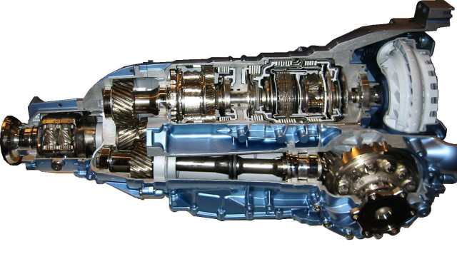
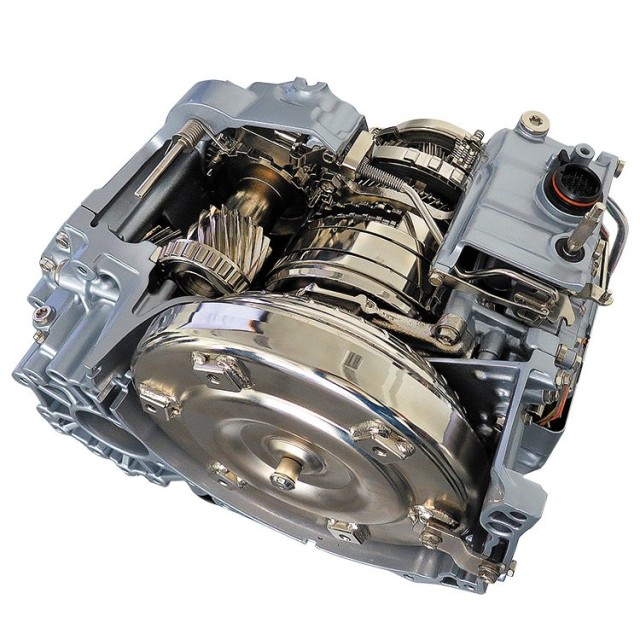
To understand the essence of automatic transmission, let's compare it with a simple manual transmission. Let us briefly consider the main components of an automatic transmission and the functions that they perform (Fig. 1)
Fig.1. The main components of an automatic transmission:
1) Torque converter (GT) - corresponds to the clutch in a manual transmission, but does not require direct control from the driver.
2) Planetary gear set - corresponds to the gear block in mechanical box gears and serves to change gear ratio in an automatic transmission when shifting gears.
3) Brake band, front clutch, rear clutch - components through which gear shifting is carried out.
4) Control device - controls gear shifting in a transmission with an integrated electronic control system.
The automatic transmission shifts gears independently depending on the vehicle speed and provides the driver with a pleasant and comfortable driving environment. The driver is only required to manually select the direction of movement of the machine: forward or backward.
This is the part that is responsible for the "direct" all operations, works with a complex system of valves and hydraulic circuits with several pressures. It has a labyrinth of carved chains that are controlled by valves. Manual valve: prevents or allows oil to pass to line pressure. Sequence valves: they are 3 and controlled by other 3 solenoid valves. Other valves besides the above, there are other valves such as pressure limiters, cutting, line pressure limiting. Pressure control valve: regulates line pressure. . The hydraulic control system has four functions.
2. Torque converter. General device and principle of operation.
A torque converter (GT) (or a torque converter in foreign sources) is used to transmit torque directly from the engine to the elements of an automatic transmission (AT) and consists of the following main parts (Fig. 2):
- pump wheel or pump (pump);
- GT blocking plate (lock - up piston);
- turbine wheel or turbine (turbine);
- stator;
- overrunning clutch (one - way clutch).
Pressure Generation System: A pump supplies pressure to all hydraulic controls and the clutch. Pressure control valve: The pressure control valve controls the main pressure to a value that depends on the opening throttle valve carburetor. This centrifugal valve regulates change in both directions depending on the speed of the vehicle.
Chain control valve: This manual valve allows you to enter different speeds as desired by the driver, 1st and 2nd and 1st stage valves, and 2nd and 3rd and 2nd stage valves. Couplings, servos and pressure accumulators: Two clutches and two servos are hydraulically offset to drive the clutches and tighten the belts.
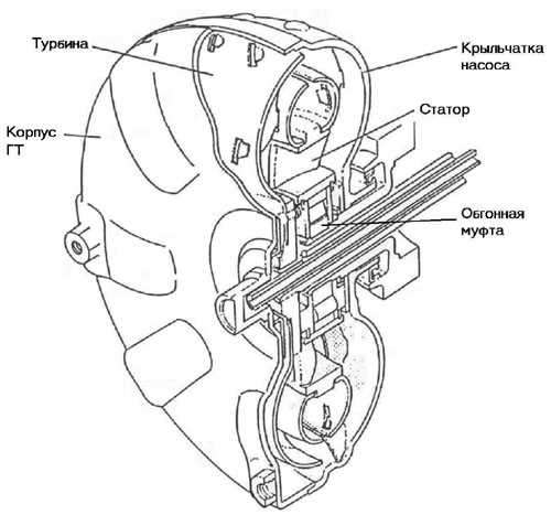
Rice. 2. General device torque converter
To illustrate the principle of operation of GT as an element that transmits torque, let's use an example with two fans (Fig. 3). One fan (pump) is connected to the network and creates an air flow. The second fan (turbine) is turned off, however, its blades, perceiving the air flow, created by the pump, rotate. The speed of rotation of the turbine is less than that of the pump, it sort of slips in relation to the pump. If we apply this example in relation to GT, then in it the impeller of the pump wheel acts as a fan connected to the network (pump).
With this system you can get 4 speeds forward and one reverse. It consists of 1 planetarium, 2 crowns and 2 sets of satellites. All of these are integrated into a very compact unit. The entry into motion can be made by the first planetarium, which is the central one, the second planetarium and the carrier of the planet.
It is connected to the converter by three couplings. The reaction elements are the second planetarium and the planet carrier, which can be immobilized by two brakes. The exit of the movement is always carried out by the crown. Motor element: satellite. Element Reaction: satellite.
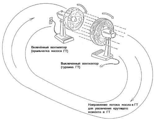
Rice. 3. Fan example
The impeller is mechanically connected to the motor. The turbine wheel acts as a switched off fan (turbine), connected through splines to the automatic transmission shaft. Like a fan - a pump, the impeller of the GT pump wheel, rotating, creates a flow, only not air, but liquid (oil). The flow of oil, as in the case of a fan-turbine, causes the turbine wheel of the GT to rotate. IN this case The GT works like an ordinary fluid coupling, only transferring torque from the engine to the automatic transmission shaft through fluid, without increasing it. An increase in engine speed does not lead to any significant increase in the transmitted torque.
Let's go back to the fan illustration. The air flow that rotates the fan blades - turbines, is wasted in space. If this flow, which retains significant residual energy, is directed again to the fan-pump, it will begin to rotate faster, creating a more powerful air flow directed to the fan-turbine. That, respectively, will also begin to rotate faster. This phenomenon is known as torque conversion (increase).
Automatic gear shift. As the speed decreases, the stride pitch advances. It is summarized as follows. The oil pump as the main element of an automobile automatic transmission. The system has been in use for over 80 years and has evolved throughout its history to the efficient and smooth units we enjoy today.
Most modern transmissions are controlled by computers, which provide almost the same fuel distribution as models. manual transmission. So, what are the main functions of the system? When you want to transfer power from the engine to the wheels. If necessary, multiply the engine torque. Reverse direction of energy flow when the vehicle is moving in reverse direction.
In GT, in addition to the pump and turbine wheels, a stator is included in the torque conversion process, which changes the direction of the fluid flow. Like the air that rotated the fan blades - turbines, the fluid (oil) flow that rotated the GT turbine wheel still has significant residual energy. The stator directs this flow back to the impeller, causing it to spin faster, thereby increasing torque. How less speed rotation of the turbine wheel of the GT in relation to the speed of rotation of the pump wheel, the more residual energy the oil returned by the stator to the pump has, and the greater will be the moment created in the GT.
In this way, they can select speeds without the intervention of the driver, i.e. they change the touch and speed of the engine according to the requirements of the vehicle. However, the system consists of different subsystems and their elements in turn. Within all the elements included in the system, there is oil pump, a vital part of the hydraulic system, and it can be considered literally the heart of the same.
The system requires a constant and sufficient supply of oil to function properly, so if the pump cannot support it, the system will not fail, which will be the end of the engine's life. Therefore, proper operation of the oil pump becomes essential for optimal engine performance. Loss of oil pressure means disappearance protective film between bearings and trunnions, which affects the cooling of the components, in addition, they fail because the oil that holds the surfaces is missing.
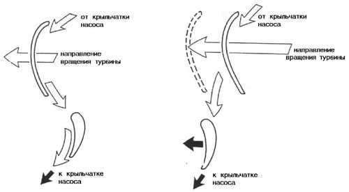
Rice. 4. GT stator is held by freewheel Rice. 5. GT stator rotates freely
The turbine always has a rotation speed lower than the pump. This ratio of the speeds of rotation of the turbine and the pump is maximum when the vehicle is stationary and decreases with increasing speed. Since the stator is connected to the GT through a one-way clutch, which can only rotate in one direction, due to the special shape of the stator and turbine blades, the oil flow is directed to reverse side stator blades (Fig. 4), due to which the stator is wedged and remains stationary, transferring to the pump inlet the maximum amount of residual oil energy remaining after the turbine rotates. This mode of operation of the GT provides maximum transmission of torque to them. For example, when starting off, the GT increases the torque by almost three times.
As the car accelerates, the slippage of the turbine relative to the pump decreases and there comes a moment when the oil flow picks up the stator wheel and begins to rotate it towards the freewheel of the overrunning clutch (see Fig. 5). GT ceases to increase torque and switches to conventional fluid coupling mode. In this mode, the GT has an efficiency that does not exceed 85%, which leads to the release of excess heat in it and, ultimately, an increase in fuel consumption by the car engine.
It is important to consider that the oil pump is subject to wear, which can be greater than other engine components, since it runs with unfiltered oil. The oil is affected by metal chips and particles from friction when system elements wear out during operation.
In addition, the transmission fluid decomposes through heat and time, which in turn generates solid deposits circulating in the fluid. These elements are removed from the system by a filter located after the pump, so that it takes oil from the crankcase without debugging.
![]()
To eliminate this shortcoming, a blocking plate is used (see Fig. rice. 6a). It is mechanically connected to the turbine, however, it can move left and right. To shift it to the left, the oil flow that feeds the GT is fed into the space between the plate and the GT body, providing their mechanical decoupling, that is, the plate in this position does not affect the operation of the GT in any way.
When the vehicle reaches high speed, on a special command from the automatic transmission control device, the oil flow changes so that it presses the blocking plate to the right against the GT body ( see fig. 6b). To increase the grip strength inside the friction layer is applied to the body. going on mechanical interlock pump and turbine by means of a plate. GT ceases to perform its functions. The engine is tightly connected to input shaft AKP. Naturally, when slightest braking vehicle lock is immediately released.
For proper maintenance oil pump is recommended. Use suitable oil. Correct work The oil pump will be largely dependent on the cleaning of the system, so regular checks and changes of the oil and filter should be performed in accordance with the manufacturer's recommendations. Always keep in mind that the conditions under which the vehicle is covered will affect the frequency of changes, high speeds, frequent and long periods of traffic jams, among other things, can shorten the periods of change.
Four types of gearbox
Would you like to learn more about automatic transmissions? One detail to consider in order to understand how to handle other gears is how maneuvers are performed in fair spaces. This manual transmission is designed in this way; with the accelerator, the necessary power is maintained and with the clutch in its middle skid zone, the approach speed is regulated.
Experimental or robotic gearbox
Up and down can be displayed both in the image and vice versa according to brands. These actions can also be performed using the steering wheels according to the models.- The number of coefficients has increased, currently it reaches 7.
- Seems difficult, but once acquired skill is easy as usual.
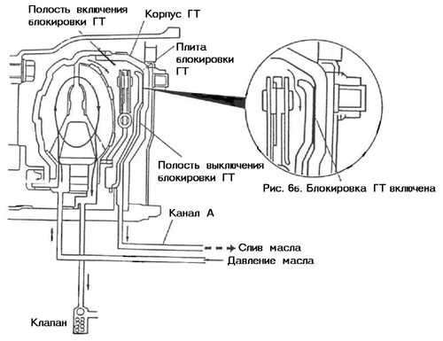
There are other ways to block the GT, however, the essence of all methods is the same - to prevent the turbine from slipping relative to the pump. In foreign sources, this mode of operation of the GT is called Lock - up (lock - up)
The GT body performs another very important function. It is used to drive the automatic transmission oil pump. For this, an additional roller is used, located inside the turbine shaft. This roller is connected with the GT body spline connection. In many automatic transmissions, the oil pump is rotated directly by the GT neck.
Automatic transmission with torque converter
These details are described in the "Transfer and Transmission" chapter of the " automotive technology". The operation can be electro-hydraulic or fully electronic. The silhouette of the image's car is a Continental Bentley, and the animation follows that order. It's simple, two turbines are very close to each other, one is attached to the engine and the other to the gearbox.
- Depending on the model, there may also be steering wheel controls.
- They are in the crankcase with pressurized oil.
- Turning the engine turbine tightens one of the boxes with some slip.
- Its work is hydraulic, there is no physical contact.
3. Planetary gears
1) The need for planetary gears.
Although the GT is capable of increasing torque, the planetary gear system in the automatic transmission is necessary for the following reasons:
- when the car overcomes the rises or during its sharp acceleration in the transmission, it is necessary to create a torque greater than one GT can create;
- the car must be able to move not only forward, but also backward.
2) planetary gears.
Unlike a simple mechanical transmission that uses parallel shafts and interlocking gears, automatic transmissions overwhelmingly use planetary gears.
The advantages of the planetary gear are its compactness, the use of only one central shaft and the way the gears are changed by locking some and unlocking other elements of the planetary gear set.
In a car with a simple manual transmission, the driver is forced to constantly and sequentially depress the clutch pedal and release the gas pedal to change gears. The automatic transmission automatically shifts gears at the right time. To do this, the driver only needs to manipulate the gas pedal, pressing or releasing it.
The planetary gear provides smooth, jerk-free shifting of vehicle speeds without the loss of engine power, jolts and bumps usually associated with gear shifting in a simple transmission.
3) Structure and theory of the planetary series.
The planetary gear (see Fig. 7) consists of the following elements:
- sun gear (sun gear);
- satellites (pinion gears);
- epicycle (internal gear);
- drove (carrier).
It has nothing to do with the "overdrive" used in a manual transmission. Implantation is carried out with a front longitudinal engine and 4 × 4. . This article is related to the "More Gain" heading of the "Clean Tech" block. If the subject interests you, you can read both for more information.
Manual and automatic shift lever
Automatic shift with steering
When driving a vehicle, we move the gear lever and feel that we can drive the car backwards or forwards; but this will happen if we do not have a gearbox. Recall that the engine, when it assimilates acceleration, receives more revs; and it gives you more power. We use the term assimilation to describe the following.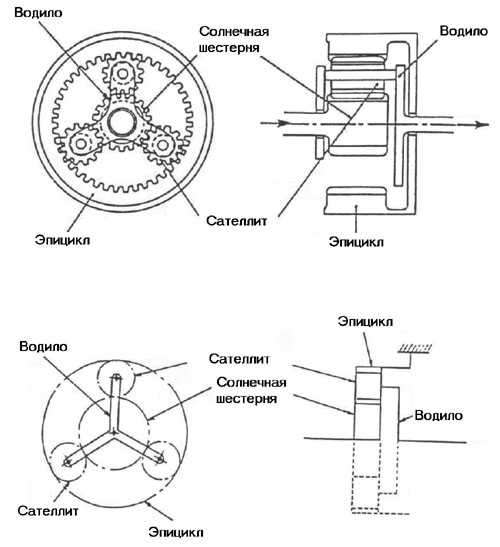
Rice. 7. planetary gear
![]()
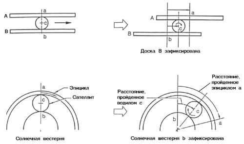
Rice. 8. Principle of 2nd gear in automatic transmission
The sun gear is in the center. The satellites rotate around the sun gear while it rotates around its own axis. The epicycle encloses the satellites that support the carrier. All satellites rotate simultaneously and in the same direction.
Switching the speed of rotation in the planetary gear set occurs when 2 of the 3 elements of the planetary gear set (sun gear, epicycle, carrier) are in certain conditions - blocked or unlocked in various combinations. What are these conditions?
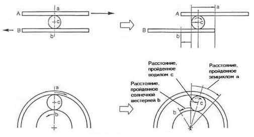
Let's consider a simple example. On fig. 8 shows ball C between boards A and B. Board B is fixed and board A moves in the direction of the arrow. In this case, ball c moves in the same direction as board A, only slower than it.
If we apply this example to the planetary gear set, then the epicycle will act as board A, the sun gear will act as board B, and the satellites will act as ball C. If you lock the sun gear and rotate the epicycle in the direction of the arrow, the planetary gear will rotate in the same direction as the epicycle. However, as with the boards and the ball, the satellite rotates more slowly than the epicycle. Such a ratio of the rotation speeds of the epicycle and satellites in the planetary gear set of the automatic transmission is carried out in second gear
If we are accelerating and the car cannot move because it is blocked hand brake or something like that prevents it from moving; the engine will not be able to assimilate and burn fuel mixture, and therefore it will sink and it will go out because it will go to the top of the revolutions since they are not controlled by the gearbox.
Flywheel or flywheel. A flywheel or flywheel is a "simple" "heavy" plate attached to crankshaft and clutch plate. This mechanical battery energy based on inherent rotational inertia. In a 6-cylinder engine, there are three pistons per engine revolution. This means that for each stroke, the engine delivers power for 3 independent torques, so "something" is needed between piston and piston to make the engine rotate and thus the flywheel. In short, it is used for: smooth delivery of engine power.
Rice. 9. Principle 1 or low gear in the AKP
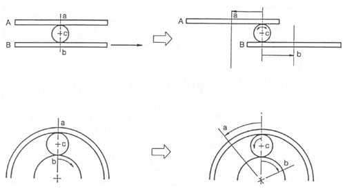
Let's think about what happens if we make the satellites, and, consequently, the carrier, move even more slowly. In the previous example board B was fixed and board A moved. This time we will slowly move board B in the direction opposite movement boards A. As shown in fig. 9, the ball moves more slowly than in the previous case. What then happens in the planetary row?
The speed at which the carrier (ball) moves by the epicycle (board A) decreases relative to the speed of the sun gear (board B) rotating in the opposite direction. As a result, the rotation speed of the carrier is less than in the previous case with the second gear. Such a ratio of the speeds of the carrier and the epicycle is carried out when the first or low gear is switched on in the automatic transmission.
Keep the engine running. Maintain kinetic energy to help the engine assemble. Steering wheel components. The clutch disc is the element responsible for transmitting all the torque to the gearbox without any slippage. For this reason, the clutch disc is coated with a friction material that sticks to metal surfaces; very resistant to wear and high temperature.
Depending on the transmitted torque and the weight of the vehicle, the dimensions of the clutch disc are calculated. It aims to control the driving force in the wheels responsible for traction, taking as a basis, the difference in pitch or rotation between the wheel, in relation to the other. it is clear that the vehicle is with a curve, one wheel covers more space than the other; also a larger wheel, it will have more space than a small one. The differential performs the function of correcting these differences. regular car receives traction or driving force on two wheels, which can be in front or behind; the result is a name rear drive or front wheel drive.
Rice. 10. Principle of 3rd gear in automatic transmission
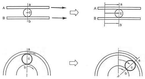
What happens if you move board A and board B in the same direction and at the same speed? Ball C between the boards cannot move on its own, therefore, it moves with them (Fig. 10). If in a planetary gear set the epicycle and the sun gear rotate in the same direction and at the same speed, the carrier rotates in the same direction and at the same speed. Such a ratio of the speeds of these elements of the planetary gear set is carried out with the third (drive) gear engaged.
Not to be confused on these pages, we will show the operation of a typical differential; the options will be explained on different pages. The leverage effect allows a small force while moving over a long distance to lift a larger weight over a shorter distance. Gears act as a series of levers. This means that the small gear rotates, albeit more slowly, by big gear, that is, the torque increases, but reduces the initial speed.
It is known as synchronization with the fact that an activated gear is connected to another that is deactivated, thus achieving that the revolutions of the first are transferred to the second, forming as if it were one part. All of these gears are arranged so that when you move the gear lever, you select the mechanism you want to activate, meaning that in order to shift from one gear to another, it must be engaged; This relationship is called speed change.
Rice. eleven. Principle reverse gear in the AKP
Let's try to move board B in the direction shown by the arrow (Fig. 11). Ball C remains stationary, rotating only around its own axis. In this case board A is moving in the opposite direction of board B. Let's apply this situation to the planetary gear set. If the carrier is fixed and the sun gear rotates clockwise (Fig. 11), the planets rotate and move the epicycle counterclockwise. In this case, if we assume that the sun gear transmits the input torque, and the epicycle transmits the output torque, then in relation to the automatic transmission we get the reverse gear.
Rice. 12. Principle of 4th gear in automatic transmission
Finally, we fix the board B and move the ball C in the direction of the arrow (Fig. 12). Then board A moves at a faster speed and in the same direction as the ball. Again we apply this situation to the planetary series. If the sun gear (board B) is locked and the carrier (ball C) rotates clockwise (fig. 12), the pinion gears rotate in the same direction around the sun gear. The speed of rotation of the epicycle is the sum of the own speed of rotation of the satellites and the speed of their rotation around the stationary sun gear. In other words, the epicycle rotates faster than the planet carrier. This ratio in the transmission is typical for the fourth (overdrive) gear.
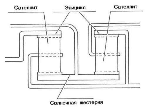
Planetary gear diagram
As a rule, 2 planetary gears are used to shift gears in a 3-speed automatic transmission, 3 planetary gears are used in a 4-speed automatic transmission, but there are exceptions, for example, AXOD automatic transmission (Ford).
4. About brakes and clutches.
|
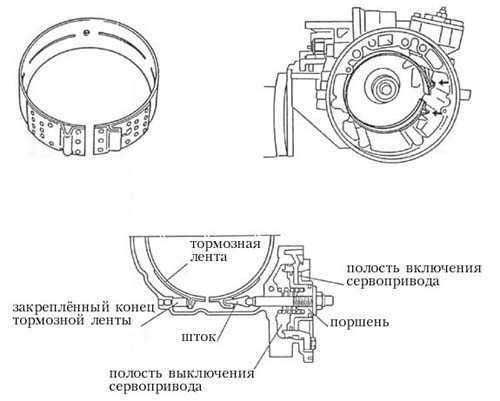
Let us consider the mechanisms through which the blocking of various elements of the planetary gear set in the automatic transmission is carried out and, consequently, switching on (off) various gears. These mechanisms are brakes and clutches. 1) Brake band (brake band). The brake band is used for temporary blocking of the elements of the planetary gear set on the body of the automatic transmission. Despite its small size, the tape has a very strong holding power. Like brake shoes, it uses a self-locking effect to lock. When the brake band is released, the shifting shock is softened as the planetary gear element holding the band begins to rotate in the opposite direction of the band's braking force. In other words, when the tape is released, it tends to release itself faster. So, we list the main advantages of the brake band: The principle of operation of the brake band. One end of the brake band is fixedly attached to the automatic transmission case, the other end is attached to the servo piston. When oil is supplied to the servo drive switching cavity (Fig. 13), the servo drive piston, moving under oil pressure (to the left in the figure), clamps the brake band, thereby blocking the planetary gear element. When oil is supplied to the servo cut-off cavity, the oil pressure in both cavities is equalized, the servo piston returns to initial position(to the right), the brake band is released.
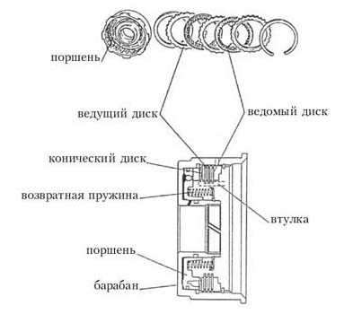
Rice. 13. Brake band. 2) Clutch system. The expediency of using friction discs in automatic transmissions is due to their following advantages: Friction principle. The clutch package consists of the parts shown in fig. 14. The input torque is transmitted from the drum (drum) to the drive discs. The driven discs are supported by a hub which transmits the output torque. The piston (piston) is driven by oil pressure. Moving under oil pressure to the right (according to the figure), the piston, by means of a conical disk (dished plate), tightly presses the leading disks of the package to the driven ones. Forcing them to rotate as a whole and transferring torque from the drum to the sleeve. As soon as the oil pressure drops, the piston under the action of the return spring (return spring) moves to the left, the drive and driven discs are unclenched, the torque is no longer transmitted through the package.
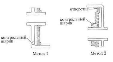
Rice. 14. Friction components. Even when the clutch is off, in the drum that rotates with high speed, the oil remaining between the drum and the sleeve is thrown under the action of centrifugal force to the inner wall of the drum. As a result, there is a residual oil pressure that is applied to the piston, forcing it to move and engage the clutch. It leads to premature wear disks and other troubles. There are 2 methods to eliminate this phenomenon (Fig. 15). Method 1.
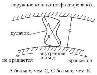
Rice. 15. Methods for eliminating the switching on of the switched off clutch. 3) Overrunning clutch (one - way clutch). The freewheel can only rotate in one direction. It consists of a movable inner race (inner race), a fixed outer race (outer race) and cams (Fig. 16).
Rice. 16. Freewheel. Operating principle. |
An automatic gearbox is a type of gearbox that provides automatic speed selection according to driving conditions. We invite you to find out in detail what an automatic transmission is, what components it consists of, and what the principle of automatic transmission is.
Development automotive industry does not stand still, and many novelties make driving for the motorist not only more convenient, but also more enjoyable. If we talk about automotive comfort, then automatic transmission immediately comes to mind - automatic, which, more than other innovations, has made life easier for motorists. This is especially true for those drivers who do not want to drive "mechanics".
"Automata" for a very long time tried to adapt to domestic market. And, nevertheless, before the time when these units will be used for the most part on our roads, it is still very far away. But in the past few decades with traditional automatic transmission manufacturers Vehicle other options for automatic ("robotic") transmissions are also offered.
Against the background of mass technologies, this type of gearbox has something in common with the usual "automatic machines" only in part. The most popular and reliable sample robotic checkpoints are from the manufacturer Volkswagen.
Automatic transmission structure
An automatic transmission differs from a mechanical one by automated gear shifting and a different principle of operation of the entire mechanical part. Here we are talking about the use of planetary devices and a hydromechanical mechanism instead of a conventional mechanical one in a standard gearbox.
As for the usual "automatic machines", in their structure they consist of:
- torque converter;
- devices - planetary gearboxes;
- moving and overrunning clutches;
- various pulleys and drums interconnected;
- a brake belt designed to brake one of the drums relative to the automatic transmission body during gear shifting.

This structure is almost all automatic transmissions. The only exception is the box of Honda cars - in such gearboxes, it was decided to replace the planetary device with pulleys with gears.
The torque converter in the "automatic" is installed in the same way as the clutch in the "mechanics". The body of this unit with the drive turbine is mounted on the flywheel of the motor in the same way as the clutch basket. main purpose this device consists in the transmission of torque with slippage when starting off. If the vehicle is moving at high engine speeds - in 3rd or 4th gear - the device locks up due to the moving clutch, making slippage virtually impossible. Thus, in automatic transmissions, unnecessary energy costs and gasoline consumption for friction disappear. transmission fluid in turbines.
The principle of operation of the box "automatic"
Now let's see how it works automatic transmission gears. If you try to disassemble the "machine" and look inside, you will see big variety various mechanisms and devices in a relatively small space.
The principle of operation of a planetary set with gearboxes is to create gear ratios. In fact, all other components of the transmission system are designed to help the planetary gear set perform this function.
The torque converter itself includes several components:
- inlet turbine;
- outlet turbines;
- stator.
Often the stator is locked to the unit body, but sometimes the braking of this turbine is activated by a moving clutch for the most efficient operation of the torque converter in any engine speed range.
The moving clutches themselves during the movement of the vehicle switch gears by connecting or disconnecting the components of the "machine". In particular, here we are talking about the input and output shafts and planetary gear components. Visually, the clutch is a cross between a clutch and a synchronizer in traditional "mechanics".
This element consists of a drum and a hub, between which there is a package of annular moving disks. The part of the disks that is connected to the drum is made of metal, and the part that is connected to the teeth of the hub is made of plastic.
The principle of operation of the clutch is to compress the package of these annular discs with a hydraulic piston, which is located directly in the drum. The transmission fluid comes to the cylinder through pipes located in the drum, shafts and body of the "machine".
In turn, the principle of operation of the overrunning clutch is to slip in one direction and jam with torque transmission in the other. As a rule, such a coupling consists of several rings - external and internal, as well as a device with rollers located between them. Overrunning mechanisms are used to reduce the level of shock in moving clutches at the time of gear changes.
The transmission of torque itself is carried out with an increase in engine speed after switching, as a result of which one of the parts of the planetary gear rotates in the opposite direction. Accordingly, it jams in the overrunning clutch.
The gearbox control unit consists of devices that direct the transmission fluid flows to the pistons brake bands and moving clutches. The positions of these devices can be set both manually, using the gearshift lever, and in automatic mode. The automation itself in such gearboxes can be both electronic and hydraulic:
- hydraulic automation. Its principle of operation is to use ATF pressure ( gear oil) from the central regulator, which is connected to the output pulley of the box. Also, this type of control uses the ATF pressure from the pressed gas pedal, which gives it information about the speed of the vehicle and the position of the gas pedal;
- electronic automation. This type of control uses solenoids, the principle of which is to switch spools. The wires from the solenoids are connected to the control device. Thanks to the "brains", movement occurs based on data on the position of the gas pedal and overall speed cars.
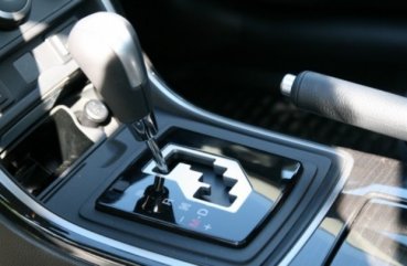
Automatic modes

Automatic transmission does not have actual switching speeds, but its device provides for operating modes, which we will consider next:
- "N" - neutral speed. Typically operated by vehicle owners while towing or when stopped for short periods of time;
- "D" is the forward position. At this point, all stages are used in the automatic transmission;
- "R" - reverse movement. This transmission is necessary for the movement of the car in reverse. In no case should this position be turned on if the car has not completely stopped;
- "L" - the position of reduced speed, often used for coasting;
- "P" - the position switched on by the automatic transmission during parking to block the drive wheels. It should also be noted here that this position of the "automatic" is in no way connected with the hand brake.

These were the main automatic transmission modes. There are also additional ones that are found on many cars:
- "O / D" - the position of the movement, which provides for the possibility of switching to more overdrive automatically. This mode is usually activated while driving outside the city at high speed;
- "D3" - the position of the box, in which only one of the first three gears is either disabled increased speeds. In this position, it is convenient to ride in urban conditions and in traffic jams;
- "S" - automatic transmission position when driving at low speeds;
- "L" - automatic transmission mode, in which only first gear works.
Video "Repair of automatic transmission"
This video describes the process of repairing an automatic transmission at a service station.
Did you like this video? Maybe you have something to add about the "automatic" box? Leave your comment!