All fuses, as well as unloading and control relays used in the system of cars UAZ Patriot, UAZ Pickup and UAZ Cargo with a ZMZ-40906 engine are installed in relay and fuse blocks. One is located in the passenger compartment, the other in the engine compartment of the vehicle.
Before replacing a blown fuse, the cause of the blown fuse must be investigated and repaired. When removing relays and fuses, do not use metal objects.
Relay and fuse box in the passenger compartment of the UAZ Patriot, UAZ Pickup and UAZ Cargo.
The relay and fuse box located in the passenger compartment is located under the cover on the instrument panel to the left of the steering column. The relay and fuse layout diagram is located on the inside of the block cover. This relay and fuse box contains the following relays:
- Relay for turning on fog lights.
- Relay for turning on the high beam headlights.
- Relay for auxiliary heater of the passenger compartment.
- Relay for turning on the dipped headlights.
- Compressor relay.
- Relay for heating the tailgate glass and mirrors.
- Relay-breaker wiper.
- Additional unloading relay.
- Heated windshield relay.
- Time relay for heating the windshield.
- Rear axle differential lock relay.
F1 10 Amp to Dymos transfer case terminal 15.
F2 15 Amperes, to the salon socket.
F3 at 10 Amperes, to the air conditioning compressor.
F4 30 Amperes, to terminal 30 of the electrical control unit.
F5 for 7.5 Amperes, on the brake light switch, interior lamps, glove compartment lighting, luggage compartment lighting.
F6 40 Amperes, for the heating and air conditioning system, the switch for heating the tailgate and mirrors.
F7 at 10 Amps, on the left fog lamp.
F8 at 10 Amperes, to the right fog lamp.
F9 20 Amp, to the wiper switch, wiper, driver switch block, rear passenger switch block, rear body heater.
F10 20 Amperes, for heating the glass of the tailgate, mirrors, lighting control module.
F11 - not installed, reserve place.
F12 20 Amp, on and the outlet in the luggage compartment.
F13 30 Amp, to terminal 30 of the Dymos transfer case.
F14 10 Amp, on power windows, driver's door module.
F15 5 Amperes, to terminal 34 of the instrument cluster, reverse switch, terminal 1 of the speed sensor, terminal 2 of the hazard switch.
F16 15 Amp, on safety.
F17 at 10 Amperes, to the media system.
F18 15 Amp, for differential lock.
F19 at 10 Amperes, on the high beam of the left headlight.
F20 at 10 Amperes, on the high beam of the right headlight.
F21 at 7.5 Amperes, for the low beam of the left headlight.
F22 at 7.5 Amperes, for the low beam of the right headlight.
F23 5 Amp, on the right side lights.
F24 5 Amp, on the left side lights.
F25 60 Amp, for heated windshield.
F26 10 Amp, standby.
F27 10 Amp, standby.
F28 30 Amp, standby.
F29 25 Amp, standby.
F30 20 Amp, standby.
To access the relay and fuse box located in the passenger compartment of the UAZ Patriot, UAZ Pickup and UAZ Cargo, you must:
- Disengage the two latches on the underside of the block cover located in its lower part.
- Unlock five clips one by one, located along the perimeter of the cover, applying force in a horizontal plane, in directions opposite to the movement of the car.
- Carefully remove the cover without using excessive force.

The relay and fuse box located under the hood in the engine compartment is located on the left extension of the car's mudguard. The relay and fuse layout is located on the inside of the box cover. This relay and fuse box contains the following relays:
- Starter relay
- Relay No. 1 of the pre-heater.
- Relay No. 2 of the pre-heater.
- Horn relay
- The main relay of an integrated microprocessor-based engine control system.
- The relay of the electric petrol pump.
- Relay for the first electric fan of the cooling system.
- Relay for the second electric fan of the cooling system.

And the following standard automotive fuses that protect electrical circuits:
F1 at 15 Amperes, for a sound signal.
F2 - not installed, reserve place.
F3 at 30 Amperes, for the electric fan No. 2 of the cooling system.
F4 25 Amperes, to the ABS brakes (ESP electronic stability control system).
F5 for 5 Amperes, for instrument cluster devices.
F6 20 Amperes, for a submersible electric petrol pump.
F7 at 20 Amperes, to the starter.
F8 at 30 Amperes, for the electric fan number 1 of the cooling system.
F9 for 10 Amperes, for an integrated microprocessor-based engine management system.
F10 10 Amp, anti-lock braking system ABS (electronic ESP system).
F11 for 20 Amperes, for the preheater.
F12 for 5 Amperes, for the pre-heater.
F13 for 25 Amperes, for the pre-heater.
F14 - not installed, reserve place.
F15 - not installed, reserve place.
F16 - not installed, reserve place.
F17 60 Amperes, on the mounting block.
F18 40 Amp, anti-lock brakes ABS (electronic stability control ESP).
F19 60 Amperes, on the mounting block.
To access the relay and fuses of the block in the engine compartment, you must remove its cover. It is not allowed to use replacement fuses that are not provided for by the design or do not correspond to the specified rating.
Most of the electrical circuits of the UAZ Patriot car are protected by fuses installed in the main mounting block 431.3722M and an additional relay and fuse box M150. They are also equipped with relays of devices consuming high current.
The main mounting block 431.3722M for the UAZ Patriot.
The main mounting block 431.3722M, catalog number 3160-3722010-02, is located in the passenger compartment under the instrument panel to the left of the steering column and is covered with a cover. To access the mounting block, turn the screw on the instrument cover and remove it. For the convenience of replacing fuses, plastic tweezers are included in the mounting block kit.

Electric circuits protected by fuses of the mounting block 431.3722M.
F1 - 5 Amp, instrument lighting, port side marker lights.
F2 - 7.5 Amperes, low beam of the right headlight.
F3 - 10 Amperes, high beam of the right headlight.
F4 - 10 Amperes, right fog lamp
F5 - 30 Amperes, power window system of doors, electric sunroof.
F6 - 15 Amp, portable lamp socket.
F7 - 20 Amperes, sound signal, electric drive of rear-view mirrors.
F8 - 20 Amperes, rear window heating element.
F9 - 20 Amperes, glass cleaners and washers.
F10 20 Ampere reserve.
F11 - 5 Amp, starboard side lights, license plate lighting.
F12 - 7.5 Amperes, low beam of the left headlight.
F13 - 10 Amperes, high beam of the left headlight and a control lamp for turning on the high beam of headlights.
F14 - 10 Amperes, left fog lamp.
F15 - 20 Amperes, electric door lock system.
F16 - 10 Amps, hazard warning lights and direction indicators.
F17 - 7.5 Amperes, lampshades, engine compartment lamp, brake light switch.
F18 - 25 Amp, heater, rear window heating switch.
F19 - 10 Amperes, instrument cluster, reverse light switch.
F20 - 7.5 Amp, rear fog lights.
F21 - 10 Amp, spare fuse.
F22 - 20 Amp, spare fuse.
F23 - 30 Amp, spare fuse.

The purpose of the relays located in the mounting block of the UAZ Patriot.
K2 - Relay breaker.
K3 - Relay-interrupter of direction indicators.
K4 - Relay for switching on the dipped headlights.
K5 - Relay for turning on the high beam headlights.
K6 - Additional (unloading) relay.
K7 - Relay for turning on the rear window heating.
K8 - Relay for turning on fog lights.
The additional relay and fuse box M150, catalog number 3163-3722010, is located under the hood of the car, in the engine compartment on the left mudguard. To access the relay and fuses of the M150 unit, remove its cover.

Electric circuits protected by fuses of the additional relay block and M150 fuses on the UAZ Patriot.
F1 - 30 Amperes, fan relay power circuit.
F2 - 20 Amperes, starter relay power circuit.
F3 - 20 Amperes, power circuit of the electric fuel pump relay.
F4 - 5 Amperes, devices.
F5 - 25 Amp, anti-lock braking system ABS.
F6 - 30 Amperes, fan relay power circuit.
F7 - 10 Amperes, power circuit of the main relay of the engine management system.
F8 - 10 Amperes, anti-lock braking system ABS.
F9 - 40 Amp, anti-lock braking system ABS.
F10 - 80 (90) Ampere, power supply of the mounting block.
The purpose of the relay located in the relay and fuse box M150 on the UAZ Patriot.
P1 - Starter relay.
P2 - Tailgate washer time relay.
P3 - Place for the relay of the recirculation flap control unit
P4 - Electric fan relay.
P5 - Electric fan relay.
P6 - Compressor relay, set depending on the vehicle equipment.
P7 - Electric fuel pump relay.
P8 - Relay for turning on sound signals.
P9 - Relay for engine management system.
P10 - Relay, set depending on the vehicle configuration.
Features of the operation of the mounting block and the relay and fuse block.
Before replacing a blown fuse, you must first find out the cause of its blown out and eliminate it. When troubleshooting, it is recommended to look at the circuits that this fuse protects. When removing relays and fuses, do not use metal objects.
When replacing fuses and checking the electrical circuits of the car, it is not allowed to use fuses that are not provided for by the design, as well as short-circuit the wires to ground, check the serviceability of the circuits "for a spark", as this can lead to burnout of the current-carrying buses of the mounting block or relay and fuse block.
Repair of the mounting block and the relay and fuse block consists in replacing the failed relays and fuses. Soldering of wires is allowed instead of burnt out busbars.
It is not at all surprising that such a domestic SUV as the UAZ Patriot is very popular. The Ural manufacturer "rewarded" this vehicle with unique power and high cross-country ability. Making a trip on such a car, you can be sure of absolute safety, since it is no secret that this car is characterized by a high level of reliability. However, this does not mean at all that the owner of the car will not experience any problems throughout the entire operational period. Over time, parts wear out, many devices fail, while remaining completely indifferent to the fate of your "iron friend" is impossible, since one technical failure will provoke another technical failure.
There are situations when the owner of the UAZ Patriot discovers a problem related to the heating of the passenger compartment. Trying to start the stove, the owner chooses different ones, however, all attempts are unsuccessful, since the stove continues to "persist". If such a situation arises, it is important to figure out whether the heater is completely "dead" or it is working, but it sends only cold air to the passenger compartment. The further plan of action will depend on the result of your observations.
Replacement process
If, when performing any actions, the stove continues to be inoperative, then you should suspect a power failure and the following technical problems. Indeed, any surge in the power grid is dangerous for the installed equipment. For this reason, in order to prevent damage to them, the manufacturer equips any vehicle with some elements that perform protective functions.
These elements include fuses, their number installed in a vehicle is far from being a single one. Each fuse is responsible for the operation and safety of individual devices and mechanisms. They are located in the mounting block. It is not difficult to find it in the UAZ Patriot. Move into the passenger compartment, bend over in the driver's seat area and pay attention to the space under the dashboard on the left side. The fuses are in a sealed box. To directly penetrate to them, it is enough to clamp two latches, and then pull the cover towards you. You can find it based on the layout of the elements provided by the manufacturer. In this case, it is enough to pay attention to the elements responsible for the device that stopped working. If you do not have such a circuit at hand, then you will have to remove each fuse one by one and visually inspect its contacts. It will take a while, but you can still find a damaged fuse.

Sometimes there may be other troubles associated with heating the passenger compartment. In particular, the owner of the UAZ Patriot is making efforts to change the fan operating mode, but all these attempts are unsuccessful. The fan works, but only when the fourth speed is selected. In this case, counting on high-quality heating is also useless. The experts point out that these "symptoms" indicate that they are not to blame for such a technical failure. The main culprit is the failed resistor. It is not recommended to repair it, it is useful to purchase a new element and install it, having previously eliminated the useless one. It should be noted that the resistor rarely breaks down, more often it breaks down due to burning of the contacts. It is not difficult to find where the resistors on the UAZ Patriot car can stand. Again, you will have to go into the salon, bend over and turn your gaze to the space located above the gas pedal. The process of replacing the resistor is not complicated, since no additional devices need to be removed.
Also, it does not interfere at all with understanding, on a UAZ Patriot car, if the heater starts to work only when the engine warms up well enough. Finding the relay is also easy, since you only need to shift your gaze to the center console, which is embedded just below the dashboard. We recommend that you do not strive to repair the relay, but rather save your own nerves and purchase a new element. Repair measures will still not lead to positive changes, thanks to which the successful operation of the heater will be able to resume.

So, take your time to the service station if you suddenly notice that. Many problems can be easily solved if you first arm yourself with the necessary information. For this reason, we recommend that you study the recommendations of the masters and, rolling up your sleeves, independently remove the detected damaged element, purchase a new analogue and install it. The result of the work will delight you when the interior of your favorite car is quickly filled with streams of warm air. You will be especially pleased that you do not need to spend your hard-earned savings on paying for the services of craftsmen.
Fuses are used to protect sections of the electrical circuit against overloads and short circuits. And often, to eliminate the malfunction, it is enough to change the fuse link. The main thing is to know where they are.
The engine control unit
The electrical diagram of the engine control unit for the UAZ Patriot release since 2012 is shown in Fig. 1. It is made in accordance with the Euro 4 standard. Some cars use a slightly modified circuit with four ignition coils.
The decoding of the block elements is given in the table in Fig. 2

The above factory specification of assemblies uses somewhat unfamiliar military-industrial terminology. For example, the crankshaft sensor is called the timing sensor, the camshaft sensor is called the phase sensor, and the idle speed control is called the auxiliary air regulator. The essence of the functions performed does not change from this.
A very useful addition is the presence of a standard OBDII connector for carrying out diagnostic work. Not all universal diagnostic scanners can fully read UAZ Patriot errors, but any simple autoscanner can diagnose engine errors in OBDII mode.
The pinout (location and numbering of pins) of the control unit looks like Fig. 3:

The most problematic units of the UAZ Patriot engine control system, as in other cars, are:
- ignition coils;
- idle speed regulator;
- synchronization sensor;
- gasoline pump.
Taking into account the harsh operating conditions of the car, it is necessary to timely (preferably with a doubled frequency) perform routine maintenance related to the operation of these units, namely:
- clean the spark plugs and zones of high-voltage ignition signals, including the housing of the ignition coils, to reduce the likelihood of breakdown;
- clean the throttle valve area of dust, regularly change the air filter;
- make sure that dust and dirt do not get into the gas tank, once a year, clean it from settled dirt and impurities;
- clean the electrical wiring from dirt, dust, oil leaks.
The wiring diagram of the ABS / ESP unit of the UAZ Patriot release since 2012 is shown in Fig. 4

On slippery road surfaces, the ABS and ESP unit significantly increases the stability of the vehicle, hence driving safety. The most common cause of failure of the ABS system is a break in the wiring connection to the wheel sensors (FL front left - front left, FR - front right, RL and RR - front left and front right, respectively). In this case, they must be “ringed” with a multimeter to the ABS unit in accordance with the diagram.
Fuse blocks
Any electrical repair usually begins with checking the fuses and control relays.
The passenger compartment relay fuse box is located below the dashboard under the cover. To gain access, you must press the latches, releasing the cover from the hooks.
The layout of the cabin fuses and relays is shown in Fig. 5

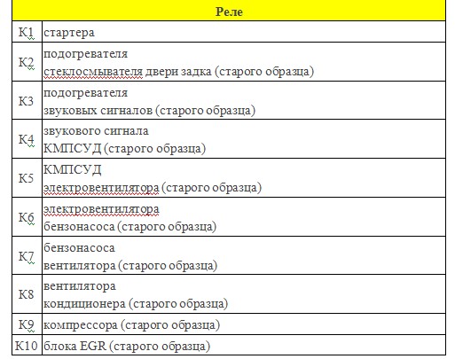
The designation of the relay is shown in Fig. 6:

The purpose of the fuses is shown in the table in Fig. 7

It should be noted that some modifications have a slightly modified fuse sequence; for clarification, you should be guided by the vehicle operating instructions.
View of the fuse box located in the engine compartment Fig. 8

It is located behind the battery Fig. 9

The decoding of relays and fuses is given in the table in Fig. 10 and 11

Usually, if problems arise with starting the car, the first step is to start checking the relays and fuses located in the engine compartment. In the event that there is a suspicion of a malfunction of any relay, you can temporarily swap places with a similar one from an adjacent socket, if any.
It is imperative to check the serviceability of the fuses by removing them from the socket using two methods: visual and using a multimeter (dial tone).
As in all cars, so in the UAZ Patriot, most of the electrical circuits are protected by fuses and controlled through power relays. This classic solution allows you to avoid overloads for electrical wiring in the car, as well as to divide all circuits into control and power. If a fuse blows out in the circuit, then one or more of the functions on the machine stops working. In order to remedy the situation, it is necessary to replace the fuse.
Before we talk in more detail about the fuses and relays installed on the UAZ Patroit, we will give general information about the generally accepted colors and ratings of fuses for current, in accordance with them.
The machine is fitted with a fuse with the same rated currents and colors as shown in the table above.
Relays and fuses in the electrical mounting block of the passenger compartment
There are 7 relays installed in the mounting block of the passenger compartment. Their functional purpose is indicated in the table below ...
In addition to the relay, 23 fuses are installed in the unit. Their rated current and the indication of the circuits that they supply are prescribed in the following table ...
| Fuse number | Current strength, A | Protected circuits |
| 1 | 10 | Spare |
| 2 | 20 | Too |
| 3 | 30 | Spare |
| 4 | 5 | Instrument lighting lamps, left side marker lights |
| 5 | 7,5 | Low beam, right headlight |
| b | 10 | High beam, right headlight |
| 7 | 10 | Right fog lamp |
| 8 | 30 | Power windows for doors, electric sunroof |
| 9 | 15 | Plug socket for portable lamp |
| 10 | 20 | Horn, electric side mirrors |
| 11 | 20 | Heated rear window |
| 12 | 20 | Glass cleaners and washers |
| 13 | 20 | Reserve |
| 14 | 5 | Side lights and license plate lights |
| 15 | 7,5 | Left headlight low beam |
| 16 | 10 | High beam of the left headlight, control lamp of inclusion of a high beam of headlights |
| 17 | 10 | Left Fog Lamp |
| 18 | 20 | Electric door locking system |
| 19 | 10 | Direction indicators and hazard warning lights |
| 20 | 7,5 | Courtesy lights, engine compartment light, brake lights |
| 21 | 25 | Heater, cigarette lighter |
| 22 | 10 | Instrument cluster, reversing light switch |
| 23 | 7,5 |
Rear fog lights |
External view of the electrical mounting block located in the passenger compartment.

In addition to the cabin mounting block, another block is installed on the machine, which is located in the engine compartment.
Relays and fuses in the electrical mounting block in the engine compartment
|
1 |
Fuse Current, A 30 |
Protected circuits Fan relay power circuit |
| relay | Name | |
| Р1 | Starter relay | |
| P2 | Tailgate washer time relay | |
| P3 | Space for the relay of the recirculation flap control unit | |
| P4 | Electric fan relay | |
| P5 | Too | |
| P6 | Compressor relay * | |
| P7 | Electric fuel pump relay | |
| P8 | Relay for turning on horns | |
| P9 | Engine control relay | |
| P10 | Air conditioner relay * |
General view of the location Relays and fuses in the electrical mounting block of the engine compartment

In the event of a fuse or relay failure, they are replaced, since they are not repairable. Burnt fuses can be identified by their appearance, by a blown jumper. Burnt out relays can be identified by the lack of functions they provide.