Oil in the KamAZ bridge is one of the most important conditions for long-term operation.
For the correct and durable operation of the mechanisms, the volume of oil in the KamAZ bridge must correspond to the established level. The brand of the oil used, as well as its timely replacement, is of decisive importance.
How much oil to pour into the KAMAZ bridge
How many liters of oil are poured into KamAZ bridges? The design features set different amounts of lubricant in the final drive housings. All-terrain vehicles of the Kamsky Automobile Plant are equipped with a front drive axle, which also requires lubrication. Its cavity holds 5.3 liters of oil. In addition, steering knuckle assemblies need lubrication.
The presence of the center differential mechanism determines how much oil to fill in the middle KamAZ axle. The gearbox needs seven liters of grease. The center differential attached to it also needs an additional 750 grams of oil.
The plant has about 80 types of bridges, they all have a similar structure, but there are exceptions. Therefore, in any case, be guided by the level of the control holes.
In the middle part of the crankcase there is a control hole, through which it is determined how much oil to pour into the rear axle of KamAZ. Unscrew the control hole plug, and add oil to the filler hole until it appears in the control hole. The check should be carried out on a horizontal platform, it is necessary to ensure that the wheels are at the same level: otherwise it is impossible to correctly determine the required level.
Do you need a KAMAZ bridge?
Which oil to choose?
Drivers do not always take a responsible attitude to what kind of oil should be poured into the KamAZ bridge. However, the wrong choice of lubricant will lead to premature wear of moving parts and failure of the machine's undercarriage assemblies.
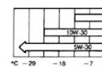
The most preferred oil for KamAZ axles is 75W-90 or 80W-90. Domestic oil can also be successfully poured into the rear axle of KAMAZ brand TAD-17i. It provides good lubricating properties, but it is unstable to low temperatures and tends to thicken in severe frosts, making it difficult for the mechanisms to work. However, most drivers use it due to its low cost.
It is better to use oil in the KamAZ bridge of famous foreign brands. Shell Spirax S6 AXME and Castrol Syntrax Long Life 75W-90 synthetic motor oils have a long service life and excellent protection of the friction surfaces of gears, bearings and shafts. They also work excellently in freezing temperatures of -40 degrees without losing their fluidity. The maximum ambient temperature for their application is 35 degrees.
Transmission oil is also used in the middle axle of KAMAZ 80W-90. They are used in temperate climates, since the range of its operating temperatures is from + 35 to -25 degrees Celsius. One of the best in this category is the Mobilube HD. It perfectly lubricates components that are exposed to heavy loads. For fans of semi-synthetic oils, Esso Gear Oil GX is also suitable, which also has the 80W-90 brand.
In climates with a predominance of high temperatures, the best choice is oil type 85W-90. It retains its density at 45 degrees heat. The minimum thermometer reading for this category is -12 ° C.
Change of oil
The first check of the oil level is carried out after 1000 km. run, the second - after another 4000 kilometers. Subsequent checks and top-ups must be carried out every 8000 kilometers.
And after 50,000 km. a complete oil change in the KamAZ axles must be performed. To do this, the gearbox is warmed up, letting the car run. Then unscrew the plugs of all three holes: filler, control and drain. After all the used lubricant has flowed out, the cavity of the gearboxes is washed and the lower plug is tightened. Then oil is poured into the KamAZ front axle through the upper hole until it appears in the control one. Then the rest of the plugs are tightened.
TRANSMISSION
On cars, depending on models and configurations, gearboxes of models are used141, 142, 144, 152, 154, ZF-6S1000, ZF-9S1310, ZF-9S109 f. "ZF" (Germany).
Model 141 transmission - mechanical, three-way, five-speed with synchronizers in the second, third, fourth and fifth gears.
Gearbox models 142, 144 - mechanical, five-speed, with synchronizers in the second, third, fourth and fifth gears, consists of a main gearbox; models 152, 154 - mechanical, ten-stage, consists of a main five-stage gearbox and a two-stage divider located in front of the main box.
Gearbox model ZF-6S1000 - mechanical, six-speed with synchronizers in the first, second, third, fourth, fifth, sixth gears.
Gearbox models ZF-9S109, ZF-9S1310 - mechanical, nine-stage, includes a main four-stage gearbox and a planetary range located behind the main box, has an additional downshift.
Drive regulation: 1 - lock nut; 2 - adjusting screw; 3 - bolt; 4 - adjusting flange; 5 - tie bolt; 6 - thrust; 7 - stock.
Gear ratios |
|||||||||||
Model | broadcast | ||||||||||
141 | 5,62 | 2,89 | 1,64 | 1,00 | 0,724 | 5,3 |
|||||
142, 144 | 7,82 | 4,03 | 2,50 | 1,53 | 1,0 | 7,38 |
|||||
152, 154 | 7,82 | 4,03 | 2,50 | 1,53 | 1,0 | 7,38 |
|||||
6,38 | 3,29 | 2,04 | 1,25 | 0,815 | 6,02 |
||||||
ZF-6 S1 LLC | 6,75 | 3,6 | 2,13 | 1,39 | 1,0 | 0,78 | 6,06 |
||||
ZF-9 S1310 | 9,48 | 6,58 | 4,68 | 3,48 | 2,62 | 1,89 | 1,35 | 1,0 | 0,75 | 8,97 |
|
ZF-9S109 | 10,24 | 6,57 | 4,78 | 3,53 | 2,61 | 1,86 | 1,35 | 1,0 | 0,74 | 9,44 |
|
L - the lowest gear in the divider; S - top gear in the divider; R - reverse; C - low gear
Regulation of the remote drive of the gearshift mechanism control in gearboxes of models 142, 152 (with engines of models 7403-260, 740.11-240, 740.13-260)
Loosen the tie bolts 5 (see fig. Drive regulation) and unscrewing the bolts 3, provide a gap in the joint by screwing the adjusting flange one or two turns 4 for pull 6;
By loosening the lock nut 1, screw in the set screw 2, stopping this movement of the rod 7;
Having loosened the lock nut 1, screw in the set screw 2 (see Fig. Mouth new screw and lock nut ka ). by stopping the movement of the gear lever;

Set screw and lock nut: 1 - lock nut; 2 - adjusting screw.
Rotate the adjusting flange along the thread 4 (see fig. Re drive regulation) until full contact with the stem flange 7. Install the bolts 3 and tighten the tie bolts 5;
Unscrew set screw 2 by 21 mm andlock it with a lock nut;
Remove the set screw 2 (see Fig.Set screw and lock nut) 31 mm and secure with the lock nut.
Adjustment of the remote (central) drive of control of gearboxes of models 152 (with engines of models 740.30-260, 740.31-240) and 154 with the option of using a power take-off on the top hatch and on the flywheel housing(see fig. Drive (central) control mechanismMoM Gear Shift Gearbox Model 152 and Drive (central) control mechanismgear shifting model 154)
Unscrew bolts 9;
Loosen nuts 14, 15 and 16;
Fix the rod 4 in the neutral position by screwing in the screw 5;
Fix the rod 3 with the technological rod 6 in the support of the gear lever 1;
Screw the adjusting flange 7 until it touches the entire plane with the flange of the rod 4 (for the gearbox mod. 154, provide dimension C equal to 30 ± 1 mm), connect the rod 8 with the rod 4 with bolts 9;
Fasten the adjusting flange 7 to the rod 8 with bolts 10, tightening them with a torque of 50 ... 70 Nm (forgearbox mod. 152), 75 ... 95 Nm (for gearbox mod. 154);
For gearbox mod. 154: screw the shank 11 into the rod 3, setting it perpendicular to the inclined plane of the lever 12 and aligning the axis of the tapered pin with the axis of the hole in the lever 12;
Rotating part M of the jet thrust 13, set the lever 1 and the rod 3 in the vertical plane;
Tighten nuts 14, 15 and 16;
Screw in screw 5 to the indicated length (21 ± 1 mm) and secure it with a nut;
Remove the process rod 6.

Drive (central) control of the gearshift mechanism of the gearbox model 152: 1 - support for the gear shift lever; 2 - rear thrust; 4 - thrust; 5 - transverse thrust; 16 - adjusting coupling flange; 23.25 - bolts; 46 - nut; Ф - stock; P - technological core; And - the screw.

Drive (central) control of the gearshift mechanism of the model 154 gearbox: 1- support of the gear lever; 2 - lever, 3 - thrust; 4 - stock; 5 - screw; 6 - technological core; 7 - adjusting coupling flange; 8 - intermediate thrust; 9 - bolt, 10 - bolt, 11 - shank; 12 - lever; 13 - jet thrust; 14, 15, 16 - nuts
Check the installation dimension of the gear divider engagement valve stop for model 152 transmission (except for transmission with engines of models 740.30-260, 740.31-240 with side drive), moving stop 4 valve stem. After setting the required value A = 20.5 ± 0.5 (see Fig.Clutch drive) fix the stop with nuts, lock the nuts with bend washers.
Divider Lever Stroke for Gearboxes Models 152, 154check with compressed air in the pneumatic drive of the brakes. For measurement:

Clutch drive: 1 - dust protection; 2 -lid; 3 - stem stop; 4 - stop (flag) of the valve stem.
Remove cover 1 (see Fig. Divider mechanism) inspection hatch of the gear divider switching mechanism;
Press the clutch pedal all the way;
Moving the gear divider control switch from the upper position to the lower position or vice versa, measure the lever travel in the center of the hole. The normal stroke is 16.5 ... 19.0 mm.
Adjust the lever travelin the following order:

Divider mechanism: 1 - inspection hatch cover; 2, 5 - adjusting screw; 3,4- lock nut.
Loosen the locknuts 3, 4 (see Fig.... Divider mechanism) and remove the set screws 2, 5;
Place the switch on the shift knob inbottom position ( H);
Press the clutch pedal all the way;
Screw in the rear set screw 5 until it contacts the lever, then turn it another 0.25 turns and lock with the lock nut 4;
Move the switch to the up position (B) and depress the clutch pedal fully. Install the front set screw 2 in the same way as the rear screw.
Adjustment of the remote actuator of the gearshift control in the model gearboxesZF-9S1310 with Cummins engine (see fig.Mechanism control drivegearshift gearbox ZF-9S1310 with Cummins engine) carry out with the neutral position of the gear lever in the following order:
Loosen nuts 9 and 10, unscrew nut 11;
Remove the shank pin 5 from the lever 7;
Unscrew the shank 5 from the rod 6;
Set the rod 4 to the position corresponding to the neutral position H1 of the third and fourth gears (see section "8.Car operation "),withstanding the size C = 251 mm;
Set the lever 7 at an angle of 5 ° ± 3 ° to the vertical;
Set the lever 2 at an angle of 90 ° ± 1 ° to the support plane (as shown in the figure). Keeping the lever in this position, screw the shank 5 into the rod 6, aligning the axis of the taper pin of the shank in the lever 7;
Tighten nut 11 to a torque of 50 ... 70 Nm and nut 9 to a torque of 98 ... 108 Nm, ensuring an angle of 90 ° ± 2 ° between the axis of the G pin and the M plane of the shank;
Rotating part AND of the jet thrust 8, set the lever 2 and the rod 6 in the vertical plane;

1 - gear shift lever handle; 2 - gear shift lever; 3 - support for the gear shift lever; 4 - stock; 5 - shank; 6 - thrust; 7 - lever; 8 - jet thrust; 9, 10, 11 - nut; And - part of the jet thrust; C - the size to the end of the rod 4 in the neutral position H1

ZF-9S1310 model gear shift control actuator with Cummins engine: 1 - gear lever handle; 2 - gear shift lever; 3 - support for the gear shift lever; 4 - stock; 5 - shank; 6 - thrust; 7 - lever; 8 - jet thrust; 9, 10, 11 - nut; And - part of the jet thrust; A - the size to the end of the rod 4 at the neutral position H1
Adjustment of the remote (lateral) drive of the gearshift mechanism control in gearboxes of models 144, 152, 154 and ZF-9S109, ZF-9S1310(see fig. Control drive mekhanizm of gear shifting of gearboxes mo Delay 144, 152, 154 and Mechanism control drivegear shifting of gearboxes of ZF- models9S109, ZF-9S1310 with KAMAZ engine) carry out with the neutral position of the gear lever in the following order:
Loosen nut 11;
Unscrew nut 9 completely;
Remove the shank 8 from the tapered hole of the lever 5 by releasing the rod 3;
Fix the rod 3 with the technological rod 4 in the support 2;
Set the lever 5 at an angle of 17 ± 2.5 ° (for model 144), at an angle of 14 ± 2.5 ° (for models 152, 154), at an angle of 16 ± 3 ° (for models ZF-9S109, ZF-9S1310) to the vertical;
Rotating the shank 8, align the axis of the tapered pin with the hole in the lever 5, tighten the nut 9 to a torque of 40 ... 50 Nm;
Keeping the shank 8 from turning with a wrench, tighten nut 11 to a torque of 98 ... 147 Nm;
Remove the technological rod;
Loosen nuts 10;
By changing the length of the rod 7, ensure theLever 1 and rod 3 in the vertical plane. The deviation of the lever 1 and the rod 3 from the vertical is no more than 2 mm;
Tighten nuts 10 to a torque of 40 ... 50 Nm.

Drive of control of the mechanism of gear shifting of gearboxes of models 144, 152.154: 1 - gear shift lever; 2 - support for the gear shift lever; 3 - thrust; 4 - rod; 5 - lever; 6 - jet thrust bracket; 7 - jet thrust; 8 - shank; 9, 10, 11- nut.

The drive for controlling the gear change mechanism of gearboxes of the ZF-9S109, ZF-9S1310 models with the KAMAZ engine: 1 - gear shift lever; 2 - support for the gear shift lever; 3 - thrust; 4 - rod; 5 - lever; 7 - jet thrust; 9 - shank; 10, 14, 15 - nut
Adjusting the position of the bolt 12 on the clutch pedalproduce if necessary for gearbox models152 (side drive), 154(see fig. Adjustment of the bolt on the clutch pedal of the gearbox gear model 154):
- screw in bolt 12, having first unscrewed its lock nut;
Press the clutch pedal all the way into the limiter;
Unscrew the bolt 12 until its spherical part touches the plane of the head of the valve stem for switching on the divider 11;
Additionally, unscrew the bolt 12 approximately by 4-4.5 turns, ensuring the head is recessed by 5-6 mm with the clutch pedal pressed all the way;
Install the bolt locknut 12.

Adjustment of the bolt on the clutch pedal of the model 154 transmission:8 - front panel; 11 - divider activation valve; 12 - adjusting bolt; 13 - clutch pedal; I - to the center differential lock valve.
CHECKING THE OIL LEVEL
Gearbox oil levelmodels 141,142,144,152,154check with a pointer mounted in the cork 2 filler hole (see fig.Oil drain plugs in the crankcase of the model 141 and Oil drain plugs in case crankcases of models 142. 144. 152. 154 ) oil filler neck. The normal level should reach the top mark on the gauge. When checking the level, do not screw in the plug, but only insert it into the hole until it stops in the thread.
For gearboxesmodels ZF-9S109, ZF-9S1310, ZF-6S1000the oil level must reach the lower edge of the filler (inspection) holes (see. rice. Drain plugs oil in the crankcase Robot models ZF-9S109. ZF-9S1310 and Oil drain plugin the crankcase model ZF-6S1000).

Oil drain plugs in the crankcase of the model 141 gearbox: 1 - drain plug;2 - filler plug;3 - control hole plug

Oil drain plugs in crankcases of boxes models 142, 144, 152, 154: 1,3,4- drain plug;2 - plug of the filling (control) hole

Oil drain plugs in the crankcase models ZF-9S109, ZF-9S1310: 1,2 - drain plug;3 - plug of the filler (check) hole
CHANGE OF OIL
Drain the oil from the crankcase when it is still warm from the heat during operation;
For boxes models 141, 142, 144, 152, 154 -unscrewing plugs 1, 3, 4 on the box with a divider (1 and 4 - without a divider);
For boxes models ZF-6S1000, ZF- 9S109, ZF-9S1310- unscrewing the plugs of one of the filler holes 3 and plugs 1, 2.
Clean the magnetic plugs from dirt, and after draining the used oil, reinstall them.

Oil drain plug in the crankcase of the ZF-6S1000 box: 3 - plug of the filler (control) hole; 1,2 - drain plug
Malfunction | Possible reason | Remedy |
Adjust the lever travel |
||
The adjustment of the installation size of the stop of the valve for switching on the gear divider(for transmission model 152) | Adjust the position of the stop of the gear divider switching valve (A = 20.5 ± 0.5) |
|
The position of the adjusting bolt on the clutch pedal is violated(for gearboxes 152 (side drive), 154) | Adjust the position of the adjusting bolt |
On cars, depending on the models and configurations, gearboxes of models 142, 152, 161 or ZF-9S109 from "ZAHNRADFABRIK" (Germany) are used.
Transmission model 142 - mechanical, five-stage, consists of a main gearbox; Model 152 - ten-stage, differing from model 142 by the presence of a two-stage divider located in front of the main box.
The control of gearboxes of models 142 and 152 is mechanical, remote, with a swinging lever mounted on the engine, divider control is selector, pneumo-mechanical using a switch on the gear lever.
Transmission models 161 - mechanical, eight-stage, includes a main four-stage gearbox and a planetary range-change gear located at the rear of the main gearbox.
An original design of the gear lever support is installed on the gearbox cover. It contains a rod and a gearbox control lever, a safety mechanism against accidental reverse gearing and pneumatic valves for switching the range multiplier.
Transmission
| Gear ratios | |||||||||||
| Model | broadcast | WITH | 1 | 2 | 3 | 4 | 5 | 6 | 7 | 8 | R |
| 142 | - | 6,38 | 3,29 | 2,04 | 1,25 | 0,815 | - | - | - | 6,02 | |
| 152 | L | - | 7,82 | 4,03 | 2,50 | 1,53 | 1,0 | - | - | - | 7,38 |
| S | - | 6,38 | 3,29 | 2,04 | 1,25 | 0,815 | - | - | - | 6,02 | |
| 161 | - | 8,39 | 5,50 | 3,93 | 2,87 | 2,12 | 1,40 | 1,0 | 0,73 | 11,01 | |
| ZF-9S109 | 10,24 | 6,576 | 4,78 | 3,531 | 2,61 | 1,86 | 1,35 | 1,0 | 0,74 | 9,44 | |
L - the lowest gear in the divider; R - reverse;
S - top gear in the divider; C - low gear
Remote drive regulation control the gearshift mechanism in gearboxes of models 142, 152, carry out with the neutral position of the gearshift lever in the following order:
- loosen the tie bolts 5 ( see fig. Drive regulation ) and, having unscrewed the bolts 3, provide a gap in the connection by screwing the adjusting flange 4 onto the rod 6 by one or two turns;
- having loosened the lock nut 1, screw in the set screw 2, thereby stopping the movement of the rod 7;
- having loosened the lock nut 1 (see Fig. Grub screw and lock nut), screw in the grub screw 2, thereby stopping the movement of the gear lever;
- rotating, move the adjusting flange 4 ( see figure Drive control ) until contact over the entire surface with the stem flange 7. Install the bolts 3 and tighten the tie bolts 5;
- unscrew the set screw 2 by 21 mm and secure it with a lock nut;
- remove set screw 2 ( see fig. Set screw and lock nut ) by 31 mm and secure with the lock nut.

Check the gap in the divider switching valve with the adjusted clutch release drive and the nominal compressed air pressure in the pneumatic brake drive in the following order:
- remove the rubber dust protector 1 ( see fig. Clutch drive );
- smoothly press the clutch pedal to the stop;
- check the gap between cover 2 and stem stop 3 with a feeler gauge.

At the nominal pressure of compressed air in the pneumatic drive of the brakes, the gap should be 0.2 ... 0.3 mm. Check the clearance no later than 30 seconds after disengaging the clutch.
If necessary, adjust the clearance by moving the stop (flag) 4 of the valve stem. After setting the required value, fix the stop with nuts, lock the nuts with bend washers.
Check the travel of the gear divider lever with compressed air in the pneumatic drive of the brakes. For measurement:
- remove cover 1 ( see fig. Divider mechanism ) inspection hatch of the gear divider switching mechanism;
- press the clutch pedal all the way;
- moving the gear divider control switch (see Fig. Gear shift diagram) from the upper position to the lower one or vice versa, measure the lever stroke in the center of the hole. The normal stroke is 16.5 ... 19.0 mm.
 Gearshift control drive
1 - gear shift lever;
2 - support for the gear shift lever;
3 - thrust;
4 - rod;
5 - lever;
6 - jet rod bracket;
7 - jet thrust;
8 - protective casing;
9 - shank;
10 - nut.
Adjust the lever travel in the following order:
- loosen the lock nuts 3, 4 (see Fig. Divider mechanism) and unscrew the set screws 2, 5;
- Place the switch on the gear shift knob in the down position (H);
- press the clutch pedal all the way;
- screw in the rear set screw 5 until it contacts the lever, then turn it another / 4 turns and lock with the lock nut 4;
- Move the switch to the up position (B) and depress the clutch pedal fully. Install the front set screw 2 in the same way as the rear screw.
Adjustment of the remote control drive of the gear change mechanism of gearboxes of models 161 and ZF-9S109 (see Fig. Control drive of the gear change mechanism) with the neutral position of the gear change lever in the following order:
- install the shank 9 in the tapered hole of the lever 5, tighten the nut 10 with a torque of 40 ... 50 Nm, for model 161, use a cotter pin;
- remove the technological rod;
Oil drain plugs in crankcases of boxes models 142, 144, 152, 154
Check the oil level in the gearbox housing with a pointer mounted in plug 2 ( see fig. Oil drain plugs in the crankcase of model 161 and Oil drain plugs in the crankcases of models 142 and 152 ) oil filler neck. The normal level should reach the top mark on the gauge. When checking the level, do not screw in the plug, but only insert it into the hole until it stops in the thread.
For gearboxes of model ZF-9S109, the oil level should reach the lower edge of the filler (check) holes 3, located symmetrically on both sides of the gearbox ( see fig. Oil drain plugs in the crankcase of the box model ZF-9S109).

Change of oil
Drain the oil from the crankcase when it is still warm from heating during operation: for boxes of models 152 and 142 - unscrew plugs 1, 3, 4 on car with a divisor (1 and 4 - without a divisor); for a box of model 161 - by unscrewing the oil filter 1 installed at the rear end of the range crankcase, and plugs 2 and 3 of the crankcase; for model ZF-9S109 - after unscrewing the plugs of one of the filler holes 3 and plugs 1 and 2 of the drain holes. Clean the magnetic plugs from dirt and, after draining the used oil, reinstall them.
Possible transmission malfunctions, causes and remedies
| Malfunction | Possible reason | Remedy |
| Difficulty shifting gears in the box | Incomplete clutch disengagement (clutch "leads") | Adjust the clutch drive |
| Self-deactivation of gears in the divider | Adjustment of the divider lever stroke is broken | Adjust the lever travel |
| The gearbox does not turn on or the gears are switched off automatically when the car is moving | The adjustment of the remote drive is incorrect or the fastening of the levers of the drive rods is loose | Adjust the actuator or tighten the arm mountings |
| Gears are not included in the divider | The adjustment of the gap in the valve for switching on the divider is broken | Adjust clearance |
TRANSMISSION
A manual transmission of model 141 is installed on the KamAZ 4308 car, which has five gears for moving forward and one gear for moving backward. For bumpless shifting of the second, third, fourth and fifth gears, two inertial finger synchronizers are used.

Rice. 3-6. Transmission (longitudinal section):1 - drive shaft; 2 - cover of the rear bearing of the input shaft; 3, 23 - shims;11 - support for the gear shift lever; 12 - axis of the block of reverse gears; 13.31 - thrust washers; 14 - block of reverse gears; 15 - roller bearing; 16 - bolt and pin assembly; 17 - lock washer; 18 - top cover; 19, 32, 36 - gaskets; 20 - cover of the rear bearing of the secondary shaft; 21 - a thrust ring; 22 - rear ball bearing of the secondary shaft; 25 - sealing cuffs; 26 - flange mounting nut; 27 - propeller shaft mounting flange; 28 - a glass of the rear bearing of the intermediate shaft; 29 - bearing cover; 30 - spherical roller bearing; 33 - intermediate shaft; 34 - transmission case; 35 - driven shaft; 37 - cover of the front bearing of the intermediate shaft; 38 - clutch housing.
Model 141 Transmission Specifications
Gear ratios | 1 - 5,62; 2 - 2.89; 3 - 1.64; 4 - 1.00; 5 - 0.724; ZX - 5.3 |
Shaft bearings | ball, spherical roller, roller |
Gear bearings | roller double-row with cages without rings, fourth gear bearing without cage |
Synchronizers | inertial type, finger with brass taper rings |
Gears | with oblique teeth, except for the first gear and reverse gear, permanent mesh |
Speedometer drive | two-stage, consists of a worm pair and a replaceable pair of cylindrical spur gears |
Lubrication system | combined. All parts are spray lubricated, the gearbox and splitter gear bearings are additionally |
The gearbox has a reversing light switch. The lamp comes on when the reverse gear is engaged.
To prevent the simultaneous engagement of two gears, a ball-type lock is installed in the cover between the rods. To prevent accidental engagement of reverse gear or first gear when the KamAZ 4308 car is moving, there is a split-type spring-finger fuse in the cover.
The seals located in the covers of the input and output shafts protect the inner cavity of the gearbox from dust and dirt and prevent oil leakage.

Rice. 3-7. Transmission mod. 141 (rear view):1 - gear shift lever; 5 - power take-off hatch cover; 6 - a sealing gasket; 8 - magnetic drain plug; 9 - drain plug; 10 - gear wheel of the speedometer drive; 11 - bushing; 16 - speedometer converter flange.

Rice. 3-8. Drive shaft assembly:1 - driving shaft; 2 - ball bearing; 3 - retaining ring of the bearing; 4 - ring nut; 5 - oil injection ring;6 - locking ball.

Rice. 3-9. Intermediate shaft assembly:1 - intermediate shaft; 2 - front roller bearing; 3 - gear wheel of the intermediate shaft drive; 4 - retaining ring; 5 - spacer sleeve; 6 - gear wheel of IV transfer; 7 - gear wheel of III transfer; 8 - key.
The gearbox consists of the following main assembly units: crankcase 34 (Fig. 3-6), in which the driving shaft 1, driven shaft 35 and intermediate shaft 33 are mounted, assembled with gear wheels, synchronizers and bearings; reverse gear block; top cover 18 of the box with a gearshift mechanism assembly. Attached to the front end of the gearbox housing is a clutch housing 38. The shaft bearings are covered with sealed covers.
Cover 2 of the rear bearing of the drive shaft with an inner bore is centered on the outer bearing race; lid surface machined on the outer diameter,is the centering surface for the clutch housing. Two self-tightening cuffs are inserted into the inner cavity of the lid. The working edges of the cuffs have a right-hand notch. The inner cavity of the large-diameter cover is designed to accommodate an oil injection device; spiral blades at the end of this cavity prevent the oil from spinning in the pumping cavity by the oil pumping ring, thereby reducing centrifugal forces and, consequently, increasing the excess oil pressure in the pumping cavity. In the upper part of the cover there is a hole for supplying oil from the gearbox oil reservoir to the pressure chamber.
The cover 20 of the rear bearing of the driven shaft is attached to the rear end of the gearbox housing, centered on the outer race of the rear bearing 22 of the driven shaft.
In the rear part of the cover there is a cuff 25 with a dust collector, on the working edge of which there is a left notch.
In the tides of the right wall of the gearbox, a bore is made into which the axle 12 of the block of reverse gears is pressed. The axle is secured from falling out with a lock washer 17, screwed with a bolt 16 having a hole into which a plastic pin is inserted. The pin seals the threaded joint, preventing the lubricant from escaping.
Oil is poured into the gearbox through the filler neck located on the right side of the crankcase. The filler neck is closed with a plug with a built-in oil dipstick.
In the lower part of the crankcase (Fig. 3-7) plugs 8 and 9 drain holes are screwed in the bosses; a magnet is mounted in the plug 8, which catches metal particles in the oil. On both sides of the crankcase there are hatches for the installation of power take-offs, covered with covers 5 with gaskets 6. The permissible value of the taken-off power is 22.06 kW (30 HP) from each hatch. Power take-off and switching on are allowed only when the KamAZ 4308 car is stopped.
In the inner cavity of the crankcase, in the front part of the left wall adjacent to the front end of the crankcase, an oil accumulator is cast, where oil is thrown in when the gears rotate, which then enters the cavity through a hole in the front wall of the crankcaseinput shaft cover and oil ring. Gear wheelsare completed in pairs with mating gear wheels along the contact patch.
Transmission drive shaft(Fig. 3-8) is made in one piece with a gear wheel; its front support is a ball bearing located in the bore of the crankshaft. The bearing cavity is filled with # 158 grease and sealed with a lip seal.
On the rear end of the shaft with an emphasis on the end face of the gear wheel, a ball bearing 2 and an oil injection ring 5 are installed, which is secured from turning on the shaft by a ball 6.
The package is tightened with a ring nut 4, the belt of which is pressed into the grooves of the shaft.
Free play of the drive shaft is regulated by a set of steel spacers 3 (Fig. 3-6) 0.2 mm and 0.3 mm thick, installed between the end of the input shaft and the outer bearing race.
Intermediate shaft(Fig. 3-9) is made as a whole with the rims of the gear wheels of the first, second gears and reverse gear. At the front end of the shaft, the gear wheels of the third 7 and fourth 6 gears and the gear 3 of the intermediate shaft drive are pressed on.
Driven shaft 16 (Fig. 3-10) assembled with gear wheels and synchronizers is installed coaxially with the input shaft. At the front end of the shaft there is a bearing 2 with an attached inner ring. All gear wheels of the shaft are mounted on roller bearings, of which the bearing of the gear wheel of the fourth gear is loose, without a separator. The gear wheels of the fourth 18 and third 7 gears in the axial direction are fixed by a thrust washer 4 with internal splines, which is installed in the groove of the shaft so that itsthe splines are located against the splines of the shaft, and are locked from turning by a spring-loaded key 21.
A channel is drilled along the axis of the shaft for supplying lubricant through radial holes to the bearings of the gear wheels. Oil is supplied to the channel by an oil injection device located on the input shaft.

Rice. 3-10. Output shaft assembly:
1 - retaining ring; 2 - front roller bearing; 3 - synchronizer for IV and V gears;4 - persistent ring; 5 - IV gear bearing rollers; 6 - sleeve of gear wheel of IV transfer;7 - gear wheel of III transfer; 8 - roller bearing; 9 - synchronizer for II and III gears;10 - gear wheel of II transfer;11 - reverse gear;12 - clutch for switching on the 1st gear and reverse;13 - pinion sleeve 1 transfers; 14 - gear wheel of 1st transfer; fifteen - washer persistent; 16 - driven shaft; 17 - reverse gear bushing; 18 - gear wheel of IV transfer; 19 - spring; 20 - intermediate sleeve; 21 - key key
Rice. 3-11. Gear shifting mechanism:
1 - plug; 2 - upper gearbox cover; 3 - shift fork for IV and V gears; 4 - adjusting screw; 5 - cotter wire; 6 - fork for shifting II and III gears; 7 - fork for switching the 1st gear and reverse.
Rice. 3-12 Shift lock and latches: 1 - the ball of the lock; 2 - a glass of a stopper ball rick; 3 - spring of the locking ball; 4 - lock pin; 5 - ball of the locking latch.
Gear shifting mechanism
(fig. 3-11) is located in the gearbox cover. Synchronizer carriages and clutch for engaging first and reverse gears are moved by a lever installed in the cab through a remote drive, rods and forks. The forks are secured with set screws on rods that move in the holes in the top cover.The gear shift mechanism consists of three rods, three forks 3, 6 and 7 of the shift, two rod heads, three clips with balls 5 (Fig. 3-12), a fuse (Fig. 62) for engaging the first gear and reverse gear and a rod lock ... The rod lock has two pairs of balls 1 (Fig. 3-12) and a pin 4. The balls are located between the rods in the bushings, the pin is in the hole of the middle rod between the balls. The diameters of the balls and the distance between the rods are chosen so that when any rod is moved from the neutral position, the balls leave the holes of the moving rod and enter the holes of the stationary rods, blocking them on the body. Above on the cover of the gear change mechanism there is a support 11 (Fig. 3-6) of a lever with a rod.
Shift Lever Support
(Fig. 3-14) consists of a bracket 1, a corrugated seal 5 of the hatch, a spring 6 of a seal, a shortened gear shift lever 4, which with its spherical part rests on a polyurethane bushing 7, which dampens the vibration of the lever. From above, the sphere is pressed through a support washer 2 by a spring. The set screw 8 fixes the shift lever in the neutral position when adjusting the drive. In working position, the bolt must be unscrewed and secured with a lock nut.
Rice. 3-13. Gearshift fuse:
1 - fuse spring; 2 - fuse;3 - fuse pusher
Rice. 3-14. Gear lever support:
1 - bracket; 2 - support washer; 3 - cover; 4 - tip lever; 5 - hatch seal; 6 - spring; 7 - polyurethane bushing; 8 - set screw.
Rice. 3-15. Model 141 gearbox shift mechanism control actuator:
3 - the handle of the gear change lever; 5 - thrust; 7 - jet thrust; 8 - gear box; 9 - engine; 10 - support for the gear shift lever; 17 - lever; 71 - nut; 100 - shank;B - gear shift lever; G - stock; K - nut.Remote control gearshift mechanism
(Fig. 3-15) consists of rocker lever B, gear shift, support 10 of the shift levertransmission, mounted on the front end of the engine cylinder block, control rod 5, shank 100, lever 17. Spherical thrust bearings 5 are located in the bore of the gear lever support bracket.Synchronizers (Fig. 3-16) consist of two tapered rings 1 and 4, rigidly interconnected by locking pins 3, and a carriage 2 moving along the splines of the output shaft. The pins in the middle have conical surfaces that are blocking. The holes in the carriage disk, through which the locking fingers pass, also have locking surfaces in the form of chamfers on both sides of the hole. The tapered rings are not rigidly connected to the carriage. They are connected to it by clamps 5, pressed by springs 6 into the grooves of the fingers.

Rice. 3-16. Synchronizer for fourth and fifth gears:
1,4 - tapered rings; 2 - carriage; 3 - blocking finger; 5 - retainer; 6 - springWhen the carriage moves with the gearshift fork, the tapered ring, moving with the carriage, is brought to the cone of the gear wheel. Due to the difference in rotation frequency of the carriage associated with the secondary shaft and the gear wheel, the tapered ring is shifted relative to the carriage until the locking surfaces of the fingers come into contactwith blocking surfaces of the carriage, which prevent further axial movement of the carriage. The equalization of the rotational speeds when the gear is engaged is ensured by friction between the conical surfaces of the synchronizer ring and the gear to be switched on.
As soon as the speeds of rotation of the carriage and the gear wheel are equal, the blocking surfaces will not impede the advancement of the carriage and the transmission will engage without noise and shock. When engaging synchronized gears with noise, it is necessary to immediately find out the cause of the malfunction and eliminate it in order to avoid premature failure of the synchronizer.
POSSIBLE MALFUNCTIONS OF THE TRANSMISSION AND WAYS OF THEIR ELIMINATION
Cause of malfunction | Remedy |
Difficult engagement of all gears, reverse gear and first gearturn on with a grinding sound |
|
Incomplete clutch release (clutch "leads") | Adjust the free play of the clutch |
High effort on the gear lever |
|
Contamination of the remote control linkages. Lack or thickening of lubricant | Rinse the supports and fill them with fresh No. 158 grease |
The inclusion of the second, third, fourth and fifth gears with a bang and grinding |
|
Wear of the cone rings of the synchronizer, blocking chamfers of the fingers and the carriage. Reduced effort required to move carriages out of neutral | Replace synchronizer |
Self-switching off of gears when the car is moving |
|
Incomplete disengagement of the transmission due to a malfunction of the clamps of the switching mechanism, wear of the paws or cracks of the forks, loosening of the forks and levers, violation of the remote control adjustment | Tighten fastening parts, replace worn parts, adjust the remote control drive |
Failure of the lock of the splines of the secondary shaft | Replace shaft and associated synchroniser |
Gears are not included |
|
Wear of parts and violation of the adjustment of the remote drive control box | Adjust the drive and replace worn parts, tighten the gear mounting parts |
Destruction of the bearings of the gear wheels of the output shaft | Replace defective parts |
Increased noise level during gearbox operation |
|
Increased wear or breakage of the wheel teeth. Destruction of gear bearings | Replace defective parts |
Destruction of shaft bearings | Also |
Oil leaks from the gearbox |
|
Worn cuffs or loss of elasticity | Replace cuffs |
Increased pressure in the gearbox housing | Flush relief valve |
Leakage violation on sealing surfaces | Tighten fasteners or replace gaskets |
Worn brass rings of gearbox synchronizers |
|
Incomplete disengagement of the clutch when shifting gears | Replace synchronizers. Check the correct operation of the clutch and drive |
Maintenance
The frequency of maintenance operations is given in the "Service Book".
During maintenance, the following operations are performed:
Fix the lever of the remote transmission drive;
Fix the levers of the rods of the remote transmission drive;
Bring up the oil level in the gearbox housing;
Fix the gearbox housing;
Fix the output shaft flange;
Change the oil in the gearbox housing;
Check the gearbox for leaks;
Clean the gearbox breathers;
Lubricate the bearings of the front and intermediate control rods through the grease fittings until fresh grease is squeezed out;
Check the axial clearance of the gearbox output shaft flange;
Change the oil in the gearbox housing.
Checking the gearbox for leaksconsists in checking by external inspection that there is no oil leakage through the sleeve of the driven shaft and gaskets.
To check the oil levelin the gearbox housing, unscrew the plug from the oil filler neck, wipe the indicator dry and insert it into the filler hole until the plug stops in the thread (Fig. 3-17) without screwing it in.
To change the oil in the gearbox, drain the oil while hot through the drain holes by unscrewing the plugs located at the bottom of the gearbox housing. Clean the drain plug magnet from dirt and metal particles. Flush the crankcase with engine oil. To do this: pour oil into the gearbox, turn it over with the engine with the gear lever in neutral for 10 minutes, drain the engine oil from the gearbox, screw in the drain plug and fill in the TSp-15K basic grease up to the upper mark of the level indicator. Crank the gearbox with the engine whenneutral position of the gear lever in those curing 3-5 min. Measure the oil level and top up if necessary.

Rice. 3-17. Position of the oil level indicator when measuring: 1 - oil level indicator from samplescoy; 2 - gearbox housing
Repair
When repairing a remote control gearbox to reduce effortwhen shifting gears, replace the grease in the drive bearings and ball heads of the articulated joints of the levers. Pump the fresh grease into the bearings through the grease fittings, screwing them instead of the plugs in the bearing housings.
If, after lubricating the bearings, the force on the lever during gear shifting has not changed or has not decreased enough, disassemble the bearings in the following order:
Unscrew the bolts securing the adjusting flange; unscrew the mounting bolts of the support on the clutch housing;
Remove the rubber cover of the swivel joint, paying attention to the safety of the restraining ball and spring;
Unscrew the shank, the reaction rod from the rod and pull the rod out of the support;
Disconnect the rod head, paying attention to the safety of the ball and the spring;
Remove the gear lever support located at the front end of the block as described below. Remove crackers, bushings, spring from the support housings. Flush the parts and cavities of the supports with kerosene or diesel fuel, replace worn sealing rings. When assembling, lubricate the rubbing surfaces with grease 158; lay fresh grease in the cavity of the supports.
After assembly, adjust the remote actuator in the following order:
Set the rod Г to neutral position;
Screw the shank 100 into the rod 5, align the axis of the tapered pin with the axis of the hole in the lever 17;
Rotating children. And the jet thrust 7, set the lever B and the thrust 5 in the vertical plane;
Tighten nuts 71 and K.
To disassemble the gearbox:
Disassemble the gearbox in the following order: unscrew the bolts securing the upper gearbox cover 25 and, screwing two bolts into the special threaded holes in the cover (after unscrewing the plugs from them), remove it; unscrew the nut 33 securing the propeller shaft flange and remove the flange, remove the front and rear bearing covers of the drive 5, driven 42 and intermediate shafts 40, screwing the mounting bolts into the special holes in the covers (when removing the covers, pay attention to the safety of the gaskets); remove the retaining ring 28 of the bearing; unlock and unscrew the two bolts securing the thrust washer of the rear bearing of the intermediate shaft; with pullers I801.30.000 remove the rear bearing 29 of the driven shaft, for this use the grip I801.30.100 (Fig.3-18). Place the grip 8 on the bearing groove and tighten with nuts 1. Turning the screw 4 into the traverse 6 and resting the tip 3 against the shaft end, remove the bearing.

Rice. 3-18. Removing the driven shaft rear bearing:1 - nut; 2 - thrust; 3 - tip; 4 - screw; 5 - axis; 6 - traverse; 7 - bearing; 8 - capture.

Rice. 3-19 Countershaft Rear Bearing Remover:
1 - glass; 2 - bearing; 3 - emphasis; 4 - tip; 5 - plate; 6 - screw; 7.8 - boltsRemove the cup 35 (Fig. 3-10) of the rear bearing together with the bearing 37 of the intermediate shaft. To remove the intermediate shaft bearing, resting against the stop 8 (Fig. 3-19) against the wall of the gearbox housing, screw two bolts 7 into the threaded hole of the bearing cup until they stop. Resting with the tip 4 against the shaft end, screw the screw 6 into plate 5 until complete removal bearing with glass.
When removing the intermediate shaft rear bearing cup from the gearbox housing, install a technological thrust washer between the 2nd gear rim of the intermediate shaft and the rim of the reverse gear block (to avoid damage to the teeth of the 2nd gear rim). Remove the drive, driven and intermediate shafts of the gearbox. Using a puller I801.32000, press axle 19 of the reverse gear block. To do this, set the handle 2 (Fig. 3-20) to the extreme right position, use the key to screw the screw 1 into the axle of the gear block; then screw the handle 2 on the screw 1 until the axle of the gear block is completely removed.
Remove the gear block 21 (Fig. 3-10), bearings 22 with a delivery ring and thrust washers 20.
For disassembling the driven shaft of the gearboxremove the circlip 1 (Fig. 3-14) and the front bearing 2 of the driven shaft, for this use the grip I801.30.200, install it on the bearing and tighten with the nuts 2 (Fig. 3-21). Screwing the screw 3 into the traverse 4 and resting the tip 5 against the end of the shaft, remove the bearing, then the synchronizer of the fourth, fifth gears, thrust ring 4 (Fig. 3-14) of the gear wheel of the fourth gear. To do this, it is necessary to remove the key 21 from the washer groove and turn it until the slot of the washer and the shaft coincide; remove the gear wheel 18 of the fourth gear with rollers 5 of loose bearings; press the sleeve 6 of the fourth gear, remove the key 21 with the spring 19; remove gear 7 and bearing 8 of the third gear, synchronizer 9 of the second and third gears; remove thrust washer 15, gear 14 and bearing of the first gear, clutch 12 for switching on the firstgears and reverse gears, press the splined sleeve 13 of the first gear, remove the gear 11 and the bearing of the reverse gear, press the sleeve 17 of the reverse gear; remove the gear and bearing of the second gear.

Rice. 3-20. Puller of the axis of the reverse gear block I801.32.000:1 - screw; 2 - handle

Rice. 3-21. Removing the front bearing of the driven shaft:
1 - capture of I801.30.200; 2 - nut; 3 - screw; 4 - traverse; 5 - tip; 6 - bearing.To disassemble the top cover of the transmission:
unscrew the nuts and remove the gear lever supports, remove the glasses 2 (Fig. 3-16), springs 3 and balls 5 of the clips; unpin and unscrew the set screws 4 (Fig. 3-15) fastening the forks and rod heads, knock out three plugs 1, remove the gear shift rods, knock out the plugs of the rod lock, remove the balls 1 (Fig. 3-16) from the cover and the pin 4 of the lock middle stem devices; unscrew the spring cup and take out the spring 1 (Fig. 3-17), the fuse 2 and the fuse bushing.Assemble in the reverse order of disassembly, taking into account the following features:
When installing gears in a gearbox without replacing them, do not disassemble the gears running in to each other;
When installing gears from the number of spare parts, it is necessary to assemble the mating gears according to the contact patch and the noise level on gear-rolling machines. The location of the contact spot should correspond to Fig. 3-22. The location of the contact patch in the pitch circle is desirable.
When checking pairs of gears on gear-rolling machines with braking and without braking the driven gear, the noise should be even, low in tone, without knocking and grinding. High-pitched noise is not allowed:
To install the rear bearing of the intermediate shaft with a glass on the shaft installed in the gearbox and pressed against the front cover, use the I801.31.000 puller. To do this, install the washer 8 on the tip 4 (Fig. 3-23), pass the bolts 9 through the holes in the glass, screw them into the threaded holes on the gearbox housing until it stops. Resting the washer 8 on the bearing, screw the screw 6 into the plate 5 until the glass with the bearing is completely installed;
When assembling the driven shaft, pay attention to the correct installation of the bushings 6,17 and 13 bearings (fig. 3-14). The holes on the bushings must be aligned with the radial holes on the corresponding journals of the driven shaft; when assembling the bulk bearing of the fourth gear gear, 88 rollers must be laid in two rows with an intermediate sleeve 20 installed between the rows; when installing the front bearing 2 of the drive shaft, the attachment ring must be installed inward to the end of the shaft;
When pressing the gear 3 (Fig. 3-9) of the intermediate shaft drive of the gearbox, it must be heated to a temperature of 90 ° C;

Rice. 3-22. Contact patch location

Rice. 3-23. Countershaft rear bearing installer:1 - glass; 2 - bearing; 3 - emphasis; 4 - tip; 5 - plate; 6 - screw; 7.9 - bolts; 8 - washer.

Rice. 3-24. Adjustment of the axial clearance of the gearbox shafts:
1 - adjusting gaskets;2 - bearing cover;3 - sealing gasket;4 - gearbox or divider housing; 5 - retaining ring;6 - control shaft bearing;a, b, c, d - adjusting dimensionsPay attention to the serviceability of the gearbox synchronizers. The static force of lifting the carriages from the neutral position should be 275 ... 373 N (28 ... 38 kgf). The locking chamfers of the crankcase and pins must be free from significant wear.
After assembling the driven shaft of the gearbox, the end clearances on the hubs of the gears of the first, second, third gears and the reverse gear should be within 0.27 ... 0.4 mm; on the hub of the fourth gear gear - 0.265 ... 0.515 mm. The end clearance on the hub of the drive gear of the drive shaft of the gearbox divider must be within 0.375 ... 0.715 mm;
When installing the bearing caps of the drive shaft of the gearbox, as well as the caps of the driven shaft, ensure the minimum backlash of the shafts by selecting shims, for this: measure with an accuracy of 0.05 mm the absolute dimension a (Fig. 3-24) from the end of the outer ring of the bearing 6 to the plane crankcase 4 with bearing pressed against the stop 6.
For the gearbox driven shaft covers, put a gasket 3 on the sealing surface of the cover 2, measure the size with an accuracy of 0.05 mm b, determine the required total thickness with shims 1, which should be less than the difference(b-c) by 0.2 ... 0.4 mm. After selecting the required number of shims, install the cover.
Install the cover for the drive shaft of the gearbox without gaskets, while the size d from the bonding surface of the cover to the shims, ensure d = (a ... a + 0, l) selection of the number of shims;
Before installing fasteners and covers, apply an even layer of the sealing composition Anaterm-4 and on two or three turns of through-threaded holes in the crankcases, and also apply it with a continuous strip 2 ... .3 mm wide along the contour on both sides of the gaskets, the rear cover of the intermediate shaft of the box gears, power take-off hatch covers;
Lubricate the sealing lips of the drive and driven shafts with grease 158.
After assembly, when the drive shaft is rotated by hand, the shafts and gears of the transmission should rotate freely (without jamming) both with the neutral position of the gear lever and with any gear engaged.
The rods of all gears must clearly fix the rods in the neutral position and in the position of the engaged gear. Reverse gear and first gearshould be switched on only when the reverse safety device installed in the top cover is released.
Simultaneous engagement of two gears and oil leakage from the gearbox are not allowed.
When the clutch release fork shaft is rotated by hand, the clutch release clutch should move freely (without jamming) along the entire length of the drive shaft cover guide.
Adjust the engagement of the divider synchronizer gear couplings.
All repaired and assembled gearboxes must be tested on a special stand.
Test benchmust have the following equipment:
A device that provides two modes of rotation speed of the input shaft:1300 min -1 and 2600 min -1;
The clutch is connected to the transmission drive shaft and is disengagedwhen shifting gears. The moment of inertia of the clutch driven parts must not exceedshaw 12.7 N.m / cm (1.3 kgf.m / cm 2);
A braking device connected to the driven shaft and providing a braking torque of 49.1 Nm (5 kgfm) for the first gear and reverse gear and 98, 1 ... 147 Nm (10 ... 15 kgfm) ) for other programs;
A device that measures the moment on the driven shaft;
Pneumatic system for switching the divider. The air pressure in the pneumatic system must be 588 ... 686 kPa (6 ... 7 kgf / cm 2);
Devices for measuring the noise level. To lubricate the gearbox during testing, use engine oil heated to a temperature of 85 ° C.
Test gearboxes in two modes; no load and under load. When testing without load, check that the gears are engaged. The test modes for gearboxes are shown in the tables.
Gearbox test mode moth 141 unloaded
Gearbox test mode moth 141 under load
After testing, drain the transmission oil while it is still hot. At the same time, clean the drain plug magnets from metal deposits.
When installing the gearbox to the engine:
Check the condition of the drive shaft using a control spline mandrel with a height of at least 30 mm, which should move freely (without jamming) along the splines of the shaft, and then lubricate the spline end with a thin layer of grease 158;
Do not allow sharp blows, and do not load the clutch discs with the weight of the gearbox or the force of the lifting mechanism in order to avoid breakage of the clutch and the front bearing of the drive shaft located in the crankshaft;
After installing the gearbox, check the full travel of the clutch, which is 35 ... 43 mm. This move corresponds to the movement of the lever by 40 ... 50 mm, measured at a radius of 90 mm;
Before installing the remote mechanism, lubricate the working surfaces of the heads and the support of the rods with grease 158. Install the heads of the mechanism and tighten with the tie bolts. Swinging of the heads on the rods is not allowed, the Sealing covers of the head of the rods of the remote mechanism must tightly cover the seating surfaces. When shifting gears using a remote mechanism, jamming of rods in the supports is not allowed. The gearshift clamps should be clearly felt both in neutral and in any engaged gear in the gearbox;
Pour TSp-15K oil into the gearbox and check it three times for starting the engine with a starter. In this case, the clutch must be disengaged;
Check the correct installation of the clutch and gearbox with the engine running at a crankshaft speed of 1800 ... 2000 min -1, checking:
1. No jamming of parts of the clutch release mechanism.
2. Cleanliness of clutch release. To do this, completely disengage the clutch, ensuring the travel of the clutch is not more than 12 mm. This corresponds to a lever movement of 16 mm measured over a 90 mm radius. In this position, the first gear and reverse gear should be engaged without grinding, and when the direct gear is engaged, the driven shaft should not rotate. Repeat the check at least three times.
3. The noise of the transmission (sharp uneven noise and knocking are not allowed).
4. Gear shifting. Gear shifting should be carried out with the clutch disengaged without great effort and without jamming; engaging synchronized gears with a grinding noise is not allowed.
5. No oil leakage. Oil leakage is not allowed. The formation of oil stains without dropping is allowed in the places of the stuffing box seals and the installation of breathers.
Note: In the absence of a test bench, test the gearbox for unloadedfor a nominal KamAZ 4308 car on flat terrain The order of gear shifting and travel time in each gear according to the table at an engine crankshaft speed of 1400 ... 1800 min -1.
When testing gearboxes, check:
Ease of gear shifting. When shifting the second, third, fourth and fifth gears, grinding is not allowed. Engage reverse and first gear only when the shafts are stopped;
Driven shaft torque. At a drive shaft speed of 2600 min -1, the torque on the driven shaft should not exceed 9.81 N.m (1 kgf.m);
Self-switching off of gears (not allowed);
The presence of sharp uneven knocks, indicating malfunctions of units and parts (not allowed).
Removing the gearbox from the KamAZ 4308 car and its installation
To remove the transmission:
Drain the transmission oil. Tilt the cab, remove the platform floor shields to provide access to the gearbox; disconnect the batteries from the electrical circuit, disconnect the terminal connecting the main switch with the frame of the KamAZ 4308 car (the terminal is located on the battery box); disconnect and remove the wire connecting the starter relay to the "+" terminal of the battery.
Remove the hose connecting the engine intake pipe with the air cleaner connecting pipe by unscrewing the nuts and removing the bolts of the clamping clamps; disconnect the plug connections of the tachometer, speedometer, trailer socket, brake signal switch, reverse lights, pressure drop indicators in receivers; disconnect the brackets for attaching the muffler to the divider housing;
Remove the clutch hydraulic booster;
Disconnect the flange - the plug of the propeller shaft of the axle from the flange of the gearbox output shaft by unscrewing the nuts of the fastening bolts, remove the spring washers and remove the bolts; loosen the tightening straps and remove the connecting hose of the ejector pipe; disconnect the air lines from the brake control valve of the trailer with a two-wire drive;
Loosen the bolts securing the front supports of the power unit; unscrew the nuts of the bolts securing the rear engine mounts and remove the bolts;
Unscrew the bolts securing the support beam to the frame;
Remove bolts securing transmission support to transverse beam;
Hang out the power unit by the eye-bolts of the gearbox; put wooden blocks under the front and rear halves of the second frame cross member and lower the power unit (the thickness of the bars should be such that when the power unit is lowered, the rear support brackets are 50 mm higher than the rear support cushions);
Remove the pinch bolt of the front linkage of the gearbox control drive;
Disconnect the front link with the lever, remove the rubber boot, remove the ball and spring from the ball head of the lever tip;
Remove the starter mounting bolts;
Install the chain claws of the lifting device for the eyebolts on the gearbox, unscrew the bolts securing the clutch to the engine flywheel housing; take the gearbox back until the drive shaft comes out of the clutch cover, remove it and install it on the trolley.
To install the gearbox.
Before docking the gearbox with the engine, put 15 g of grease 158 into the cavity of the front bearing of the drive shaft located in the bore of the crankshaft; Lift the gearbox and install it in place, having previously installed the clutch release clutch, the hose for supplying lubricant to the pressure bearing and the return springs.
Screw in the clutch housing to the engine flywheel housing. Screw in the starter mounting bolts. Connect the front link with the lever, after inserting the ball and spring into the ball head of the lever; screw in the pinch bolt of the front linkage of the gear control drive. Adjust the remote control gearshift drive.
Hang up the power unit by the transmission eyebolts.
Screw in the bolts securing the gearbox support to the crossbeam, remove the wooden blocks from under the second frame cross member and lower the power unit onto the supports; screw in the bolts securing the support beam to the frame; insert the bolts into the holes of the rear supports of the power unit, tighten the self-locking nuts.
Tighten the power unit front mountings retaining bolts.
Connect the air lines to the brake control valve of the trailer with a two-wire drive; put on the connecting hose of the ejector pipe and secure it with the straps.
Align the holes of the yoke flange of the propeller shaft of the axle with the holes of the flange of the gearbox output shaft; insert the bolts into the holes, put on the spring washers, tighten the nuts. Install the clutch booster.
Attach the muffler mounting bracket to the gearbox housing by screwing bolts.
Connect the plug connectors of the tachometer, tachograph (speedometer), semitrailer socket, brake signal switch, reverse light, pressure drop indicators in receivers.
Install the hose that connects the engine intake pipe to the air cleaner connecting pipe.
Put on the clamping clamps and secure the hose by inserting the bolts into the holes of the clamp and tightening them with nuts.
Connect the wire connecting the starter relay to the "+" terminal of the battery; connect the output for switching on the mass with the frame of the KamAZ 4308 car (the output is located on the battery box); connect the batteries to the vehicle's electrical circuit. Put up the floor boards.
Fill gearbox housing with oil. Lower the cab.
Check and, if necessary, adjust the clutch pedal free play.
On the cars equipped with engines 740.51-320 and 740.50-360, a gearbox of model 161 or model ZF-16S151 from ZAHNRADFABRIK (Germany) is installed, on cars with 740.14-300 engines - models ZF-9S109 from ZAHNRADFABRIK (Germany).
Transmission Model 161 - mechanical, eight-stage, consisting of a main four-stage gearbox and a planetary range located at the rear of the main box.
Gear ratios:
| Model | . | C | 1 | 2 | 3 | 4 | 5 | 6 | 7 | 8 | R |
| 161 | . | - | 8,39 | 5,50 | 3,93 | 2,87 | 2,12 | 11,40 | 1,00 | 0,73 | 11,01 |
| ZF-9S109 | . | 12,91 | 8,96 | 6,37 | 4,71 | 3,53 | 2,54 | 1,81 | 1,34 | 1,0 | 12,2 |
| ZF-16S151 | L | - | 13,8 | 9,49 | 6,53 | 4,57 | 3,02 | 2,08 | 1,43 | 1,0 | 12,92 |
| S | - | 11,5 | 7,93 | 5,46 | 3,82 | 2,53 | 1,74 | 1,20 | 0,84 | 10,80 |
L - decelerating gear in the divider;
S - accelerating gear in the divider;
R - reverse;
C - low gear.
On the cover of the box there is a support for the gearshift lever, in which there are the rod and the gearbox control lever, the safety mechanism against accidental engagement of reverse gear and pneumatic valves for switching the range.
Transmission models ZF-9S109 - mechanical, nine-speed, having an additional downshift compared to model 161.
The gearbox of the ZF-16S151 model is a mechanical sixteen-speed, includes a four-speed main box with an integrated two-stage divider located in front of the main box and with a two-stage planetary range located behind the main box. 
Adjustment of the remote drive of the mechanism control gear shifting of gearboxes of models 161 and ZF-16S151 ( see fig. Gearshift control drive ) carry out with the neutral position of the gear lever in the following order:
- fix the rod 3 with the technological rod 4 (d = 4mm, l = 100mm) in the support 2;
- install the shank 9 into the tapered hole of the lever 5, tighten the nut 10 with a torque of 40 ... 50 Nm and secure it with a cotter pin;
- remove the process rod.
- the deviation of the general plane of symmetry of the lever 1 and the rod 3 from the vertical plane of no more than 2 mm should be ensured by changing the length of the rod 7.
For model ZF-9S109:
- set the gear change lever (see fig. ZF-9S109 gear change mechanism control drive) at an angle E of the vertical:
- set the lever at an angle W to the vertical;
- rotating the shank, align the axis of the tapered pin with the axis of the hole in the lever;
- rotating the jet thrust, ensure the deviation of the general symmetry plane of the gear shift lever from the vertical plane of no more than 2 mm;
- tighten and cotter the slotted nuts;
- tighten the nut.

Check the oil level in the crankcase of the 161 gearbox with a pointer mounted in the oil filler plug. The normal level should reach the top mark on the gauge. When checking the level, do not screw in the plug, but only insert it into the hole until it stops in the thread.
For ZF-9S109 and ZF-16S151 gearboxes, the oil level must reach the lower edge of the filler hole.
Change of oil
Drain the oil from the crankcase when it is still warm from heating during operation: for model 161 - by unscrewing the oil filter 1 installed at the rear end of the range crankcase, and plugs 2 and 3 of the crankcase (see Fig. Oil drain plugs in the crankcase of the model 161 box) ; for models ZF-9S109 and ZF-16S151 - after removing the filler and drain plugs. Clean the magnetic plugs from dirt and, after draining the used oil, reinstall them.

Onboard tractor vehicles produced by the Kama Automobile Plant: KamAZ-5320 since 1976, KamAZ-53212 since 1979. Designed to work mainly with trailers. The body is a metal platform with opening side and rear walls. The flooring is made of wood, the installation of an awning is provided. The cab is a three-seater, reclining forward, with noise and thermal insulation, equipped with anchorage points for seat belts, for KamAZ-53212 - with a berth. The driver's seat is sprung, adjustable according to the driver's weight, length, backrest inclination.
Main trailers: for KamAZ-5320 - GKB-8350 and -8355; for KamAZ-53212 - GKB-8352 and -8357.
Modifications:
KamAZ-5320 vehicle - KamAZ-53211 chassis and tropical version - KamAZ-532007;
the KamAZ-53212 vehicle - the KamAZ-53213 chassis and the tropical version - KamAZ-532127.
In the diagram of the KamAZ-53212 car, the dimensions for the aluminum platform are given in brackets.
SPECIFICATIONS
| Model | KamAZ-5320 | KamAZ-53212 |
|---|---|---|
| Carrying capacity, kg | 8000 | 10000 |
| Curb weight, kg | 7080 | 8000 |
| Including: | ||
| on the front axle | 3320 | 3525 |
| on the cart | 3760 | 4475 |
| Full weight, kg | 15305 | 18225 |
| Including: | ||
| on the front axle | 4375 | 4290 |
| on the cart | 10930 | 13935 |
| Permissible trailer weight, kg | 11500 | 14000 |
| Full mass of the road train, kg | 26805 | 32225 |
| Max vehicle speed, km / h | 80 | 80 |
| The same, road trains | 80 | 80 |
| Acceleration time of the car to 60 km / h, sec. | 35 | 40 |
| The same, road trains | 70 | 90 |
| Max. overcome rise by car,% | 30 | 30 |
| The same, by road train | 18 | 18 |
| Car run-out from 50 km / h, m | 700 | 800 |
| Braking distance of the car from 60 km / h, m | 36,7 | 36,7 |
| The same, road trains | 38,5 | 38,5 |
| Control fuel consumption, l / 100 km of the vehicle: | ||
| at 60 km / h | 23,0 | 24,4 |
| at 80 km / h | 29,6 | 31,5 |
| The same, road trains: | ||
| at 60 km / h | 32,5 | 33,0 |
| at 80 km / h | 43,7 | 44,8 |
| Turning radius, m: | ||
| on the outer wheel | 8,5 | 9,0 |
| overall | 9,3 | 9,8 |
Engine
Maud. KamAZ-740.10, diesel, V-o6p. (90 °), 8-cyl., 120x120 mm, 10.85 L, compression ratio 17, operating procedure 1-5-4-2-6-3-7-8, power 154 kW (210 hp) at 2600 rpm, torque 637 Nm (65 kgf-m) at 1500-1800 rpm. Injectors - closed type, TNDV - V-type, 8-section, spool type, with a low pressure fuel pump, fuel injection advance clutch and all-mode speed controller. The air filter is dry, with a replaceable cardboard filter element and a clogging indicator. The engine is equipped with an electric torch device (EFU) and (on request) a PZhD-30 pre-heater.
TransmissionThe clutch is double-disc, with peripheral springs, the shutdown drive is hydraulic with a pneumatic booster. The gearbox is 5-speed, with a front divider, the total number of gears is ten forward and two backward. numbers: I-7.82 and 6.38; II 4.03 and 3.29; III 2.5 and 2.04; IV-1.53 and 1.25; V-1.0 & 0.815; ZX-7.38 and 6.02. Synchronizers - in II, III, IV and V gears. The divider is equipped with a synchronizer, the divider control is pneumo-mechanical, preselector. Cardan transmission - two cardan shafts. The main gear is double (bevel and cylindrical), trans. number - 6.53 (by order - 7.22; 5.94; 5.43); the middle axle is a straight-through, with an interaxle differential locked by means of an electro-pneumatic or pneumatic drive.
Wheels and tiresWheels - diskless, rim 7.0-20, mount on 5 studs. Tires - 9.00R20 (260R508), mod. I-N142B, front tire pressure - 7.3; rear: KamAZ-5320 - 4.3; KamAZ-53212 - 5.3 kgf / cm 2; number of wheels 10 + 1.
SuspensionDependent: front - on semi-elliptical springs with rear sliding ends, with shock absorbers; the rear is balanced, on semi-elliptical springs, with six jet rods, the ends of the springs are sliding.
BrakesWorking brake system - with drum mechanisms (diameter 400 mm, lining width 140 mm, cam release), double-circuit pneumatic drive. Brake chambers: front - type 24, bogies - 20/20 with spring accumulators. The parking brake is applied to the bogie brakes from spring brake accumulators, the drive is pneumatic. The spare brake is combined with the parking brake. The auxiliary brake is a pneumatically actuated motor retarder. Trailer brake drive - combined (two- and one-wheel drive). There is an alcoholic protection against freezing of condensate.
SteeringThe steering gear - a screw with a ball nut and a piston-rack, engaging with the toothed sector of the bipod shaft, is transferred. number 20. The hydraulic booster is built-in, the oil pressure in the booster is 80-90 kgf / cm 2.
Electrical equipmentVoltage 24 V, ac. 6ST-190TR or -190 TM battery (2 pcs.), G-273 generator set with Y120M voltage regulator, ST142-B starter.
Filling volumes and recommended operating materials Fuel tanks:for KamAZ-5320 - 175 or 250 liters,
for KamAZ-53212 - 250 liters, diesel. fuel;
cooling system (with heater) - 35 l, cool. liquid - antifreeze A-40;
engine lubrication system - 26 liters, in summer M-10G (k) in winter M-8G2 (k), all-season DV-ASZp-10V;
power steering - 3.7 l, grade P oil;
a gearbox with a divider - 12 l, TSP-15K;
drive axle housings - 2x7 l, TSp-15K;
hydraulic clutch release system - 0.28 l, brake fluid "Neva";
shock absorbers - 2x0.475 l, liquid АЖ-12Т;
fuse against freezing of condensate in the brake drive - 0.2 l or 1.0 l, ethyl alcohol;
windshield washer reservoir - 1.8 l, NIISS-4 fluid mixed with water.
Unit weight(in kg):
Engine with clutch - 770,
a gearbox with a divider - 320,
cardan shafts - 49 (59),
front axle - 255,
middle bridge - 592,
rear axle - 555,
frame - 605 (738),
body - 870 (1010),
cab complete with equipment - 577 (603),
complete wheel with tire - 80,
radiator - 25.


In our company you can buy spare parts for the ZF checkpoint for trucks and buses. The range of offered parts is presented both by the well-known Italian manufacturers TAS Spa and Euroricambi, where high quality is combined with adequate cost, as well as original parts.
Many truck owners choose to buy spare parts for ZF boxes. They are produced by the German concern ZF, which is one of the largest enterprises in the production of transmission units, suspensions and steering.
You can buy ZF spare parts for different types of gearboxes from us, including:
- Ecolite, 5-6 speed gearboxes for light trucks and buses;
- Ecomid, enables medium-duty trucks to operate with exceptional efficiency and reach their full potential;
- Ecosplit, heavy duty truck gearbox;
- ASTronic, automatic transmission for commercial vehicles
We offer spare parts for the ZF gearbox for the entire range of transmissions of commercial trucks and buses. There is a complete list of spare parts necessary for repairing a ZF gearbox - from bots, nuts, cotter pins and other trifles to body parts.
We work directly with manufacturers of spare parts, which allows us to set minimum prices for the entire list of spare parts.
Find ZF Parts
- If you know the number of the required spare part for the ZF box, enter it in the search bar and click "Find" to see the price and availability.
- If the required spare part number is not available, but the gearbox number is known (indicated on the information plate), use the catalogs to find out the part number.
- You can always contact us and get detailed advice from our employees. They will help you select the necessary spare parts for the transmission and help you buy spare parts at the ZF checkpoint.
CANNOT FIND WHAT YOU NEED?
We will find it in the catalog ourselves, and if not, we will order and bring the spare part you need!
Catalogs
The section contains original and non-original Catalogs of ZF transmissions of various models. With the help of them, you can independently select the spare part you are interested in for the ZF box.
Those. information
This section provides information of a technical nature. Here you will find:
- - information about the design and operation features of mechanical and automatic transmissions ZF;
- - specification of lubricants with a list of oil brands approved by ZF;
- - technical characteristics of gearboxes (oil volume in the gearbox, gear ratio, weight).
Payment and delivery
Possible payment methods are presented on the Payment page. Currently, we accept payment in cash, wire transfer and payment by bank cards. We can buy spare parts for the ZF checkpoint with delivery by transport companies. By agreement, we can send ZF parts in another way or arrange express delivery. More detailed information on delivery methods is presented in the section