INTRODUCTION.. 2
1. Appointment double main gear. 3
2. Design and operation of double main gears KAMAZ-5320. 5
2.1. Devices and operation of the double final drive of the middle drive axle of the KamAZ-5320 car. 5
2.2. Devices and operation of the double final drive of the rear drive axle of the KamAZ-5320 car. 7
2.3. Devices and operation of double main gears of driving axles of the KamAZ-5320 car. 9
3. Basic adjustments of the main gear. eleven
CONCLUSION.. 15
REFERENCES... 16
INTRODUCTION
transmission, or power transmission car, serves to - transmit torque from crankshaft engine to drive wheels. In the currently most common stepped mechanical transmission includes clutch, gearbox, cardan and main gears, differential and axle shafts. The torque in such a transmission changes in steps; transmission does not provide ease of driving and full use engine power. Therefore, electric, frictional and hydraulic (hydrostatic and hydrodynamic) continuously variable transmissions (transmissions) were proposed, in which the torque changes smoothly, without the participation of the driver, depending on the resistance of the road and the speed of rotation of the engine crankshaft.
The total gear ratio of two-stage main gears is determined by the product of the gear ratios of bevel and cylindrical pairs.
On KamAZ vehicles, the main gear is two-stage with a through shaft. Its main parts are the gearbox housing, a pair of spiral bevel gear wheels and a pair of helical spur gears.
The main gear is mounted on the axle housing through a 0.8 mm thick paronite gasket and is fastened with eleven bolts and two studs. Eleven bolts and studs are installed on the outside, and two bolts are on the cavity of the comic gears. Access to the internal bolts is possible only after removing the side cover. Spring washers are installed under the outer bolts and nuts of the studs. Internal bolts are cottered with wire.
1. Appointment of double final drive
The main gear of the car is designed to constantly increase the torque supplied from the engine and transmit it at a right angle to the drive wheels.
The constant increase in torque is characterized by the gear ratio of the final drive.
The use of double gears is due to the fact that you have to transmit a significant torque, therefore, to reduce the specific load on the teeth, two pairs of gears are used - bevel and cylindrical.
Fig.1. Double final drive
1 - leading bevel gear; 2 - driven bevel gear; 3 – leading cylindrical gear; 4 - driven cylindrical gear
In the double main gear (Fig. 1), the torque is transmitted from the driving bevel gear 1 to the driven 2, mounted on the same shaft with the small (driving) spur gear 3, from which the torque is transmitted to the large (driven) spur gear 4.
In a double final drive, a large gear ratio can be obtained with relatively small gear sizes. double transmission used on trucks of medium and large capacity.
Double main gears can be single-stage and two-stage, i.e. with two shiftable gears with different gear ratios.
On KamAZ vehicles, depending on the purpose, the gear ratio of the final drive is 5.43; 5.94; 6.53; 7.22. On a Ural-4320 car, it is 7.32. On modifications of vehicles intended for use as truck tractors, gear ratios of the main gear are increased.
On the KamAZ-5320 car, double main gears are used, consisting of two gear pairs, a pair of bevel gears with spiral teeth and a pair of cylindrical gears with oblique teeth. This scheme allows you to get a large gear ratio with sufficient ground clearance main gear box.
2. Design and operation of double main gears KAMAZ-5320
2.1. Devices and operation of the double final drive of the middle drive axle of the KamAZ-5320 car
The double main gear of the middle drive axle of the KamAZ-5320 vehicle (Fig. 2) is made with a through shaft for the main gear drive rear axle. The drive bevel gear 20 is installed in the neck of the main gear housing on two roller tapered bearings 24, 2v, between the inner races of which there is a spacer sleeve and shims 25. The ground end of the hub of this gear is connected to the bevel gear center differential, and inside the hub passes the drive shaft 21, connected at one end to the bevel gear of the center differential, and at the other with the help of driveline with the main drive shaft of the rear axle.
The intermediate shaft rests at one end on two tapered roller bearings 7, between the inner races of which there are adjusting washers 4, and on the other end on a roller bearing mounted in the bore of the main gear crankcase bulkhead. Tapered roller bearings 7 fix intermediate shaft from displacement in the axial direction. At the same time with the intermediate shaft, a spur gear 3 with oblique teeth is made. The driven bevel gear 1 is pressed onto the end of the intermediate driven spur gear 16. The torque from the cross-axle differential housing, to which the driven spur gear 16 of the main gear is attached, is transmitted to the crosspiece 15, and from it through satellites to the gears of the axle shafts. Satellites, acting with the same force on the right and left gears of the semi-axes, create equal torques on them.
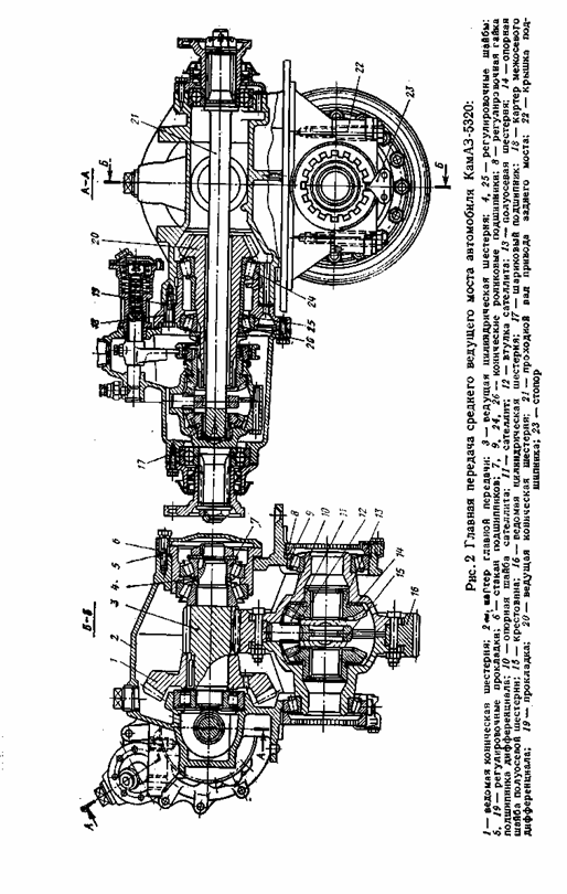
At the same time, due to insignificant internal friction, the equality of moments is practically preserved both with fixed satellites and with their rotation.
Turning on the spikes of the cross, satellites provide the possibility of rotation of the right and left axle shafts, and consequently, the wheels with different frequencies.
2.2. Devices and operation of the double final drive of the rear drive axle of the KamAZ-5320 car
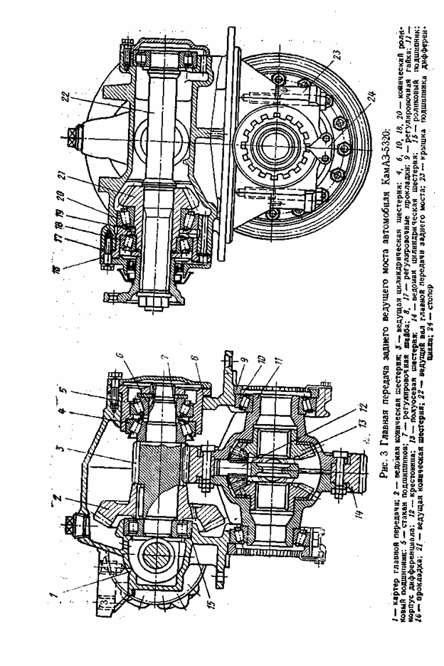
The general arrangement of the final drive of the rear drive axle (Fig. 3) is similar to that discussed above. The differences are mainly due to the fact that the rear drive axle is not a through and receives torque from the center differential mounted on the middle drive axle.
In the main gear of the rear axle, the drive bevel gear 21 differs from the similar gear of the middle axle in that its hub is shorter and has internal splines for connection with the drive shaft 22 of the main gear of the rear axle. Tapered roller bearings 18 and 20 are interchangeable with the corresponding middle drive axle bearings. The main drive shaft of the rear axle with its rear end rests on one roller bearing installed in the crankcase bore. For the circulation of lubricant near the bearing in the neck of the crankcase there is a channel. The end face of the bearing is closed with a cap. The remaining parts of the main gear of the middle and rear drive axles are similar in design.

2.3. Devices and operation of double main gears of driving axles of the KamAZ-5320 car
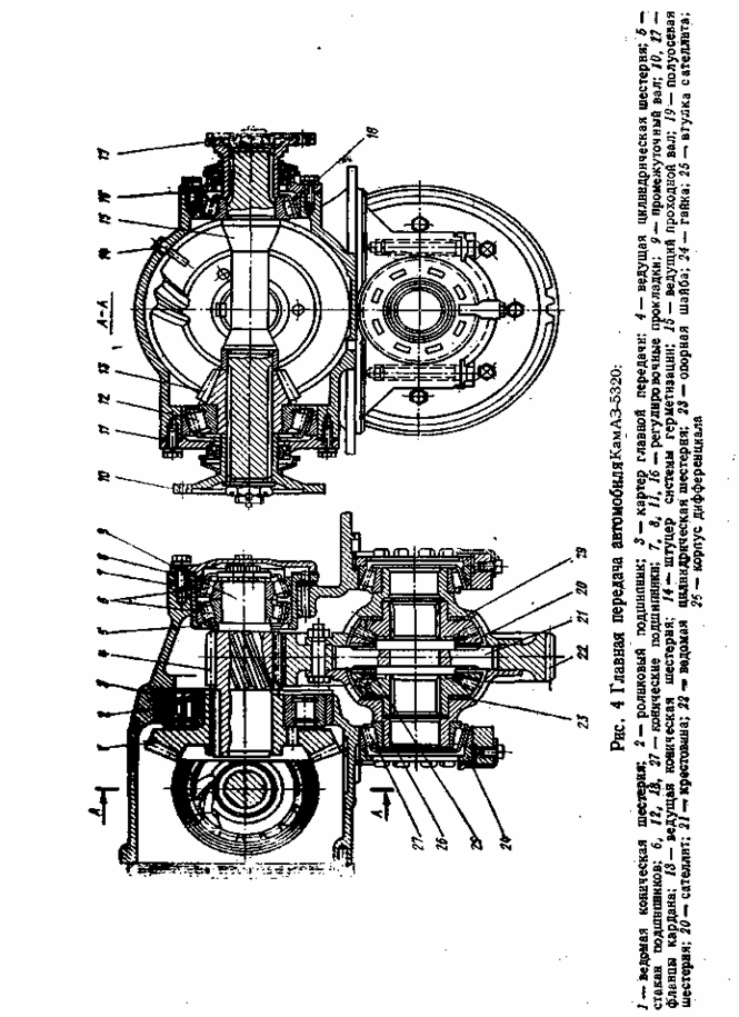
The final drive housing 3 (Fig. 4) is bolted to the axle beam. The plane of the connector is sealed with a paronite gasket 0.8 mm thick. A pair of cylindrical gears with oblique teeth are installed in the crankcase cavity. The leading bevel gear 13 is mounted on the splines of the leading through shaft 15 (for the middle bridge). This shaft rests on two tapered roller bearings 12 and 18, which are closed with caps having shims 11 and 16. The output ends of the shaft are sealed with self-compressing glands protected by mud-reflecting rings. At the ends of the through shaft (for the middle axle), universal joint flanges 10, 17 are installed. The flange 17 of the drive to the rear axle is smaller in size than the flange 10, which is supplied with torque from the center differential of the transfer case.
The intermediate shaft 9 of the main gear is mounted on a cylindrical roller 2 and two conical roller bearings 6 mounted in a glass 5. Adjusting shims 7 and 8 are placed under the flange of the glass and the bearing cover. The driven spur gear 22 is connected to the halves (cups) of the differential housing, each of which is supported by a tapered bearing.
3. Main gear adjustments
In the main gear, the tightening of the tapered bearings of the driving bevel gear (KamAZ-5320), bearings of the drive through shaft, tapered bearings intermediate shaft and housings of the cross-axle differential. The bearings in these units are adjusted with preload. When adjusting, the preload must be checked very carefully to avoid malfunctions, since too much tightening of the bearings leads to their overheating and failure.
In the main gears, the possibility of adjusting the engagement of bevel gears is also provided. However, it must be borne in mind that it is not advisable to adjust the working pair during operation. It is carried out with a repair or a new set of a pair of bevel gears when replacing a worn pair. Adjustments of bearings and engagement of bevel gears are carried out on the main gear removed from the car.
The bearings of the main bevel gear of the main drive of the middle drive axle of the KamAZ-5320 vehicle are adjusted by selecting the required thickness of two shims (see Fig. 2), which are installed between the inner ring front bearing and spacer sleeve. After installing the shims, the fastening nut is tightened with a torque of 240 Nm (24 kgf "m). When tightening, it is necessary to turn the drive gear 20 so that the rollers take correct position in the bearing cages.
Then the locknut is tightened with a torque of 240-360 Nm (24-36 kgf-m) and fixed. The bearing preload is checked by the torque required to turn the drive gear. When checking, the moment of resistance to turning the drive gear in the bearings should be 0.8-3.0 N - m (0.08-0.30 kgf - m). It is necessary to measure the moment of resistance with a smooth rotation of the gear in one direction and at least after five full revolutions. Bearings must be lubricated.
Adjustment of the bearings of the main bevel gear of the rear drive axle of the KamAZ-5320 vehicle (see Fig. 3) is carried out by selecting the required thickness of the shims, which are installed between the inner race of the front bearing and the support washer. The moment of resistance to turning the drive gear shaft should be 0.8-3.0 N-m (0.08-0.30 kgf-m). When checking this moment, the bearing cup cover must be moved towards the flange so that the gland does not resist rotation. After the final selection of shims, the flange nut cardan joint tighten with a torque of 240-360 Nm (24-36 kgf-m) and cottered.
The tapered roller bearings (see Fig. 2) of the intermediate shaft of the main gear of the KamAZ-5320 vehicle are adjusted by selecting the thickness of two shims that are installed between the inner races of the bearings. The moment of resistance to turning the intermediate shaft in the bearings should be 2-4 Nm as when adjusting the bearings of the drive gear.
The preload of the tapered roller bearings of the differential housing is adjusted using nuts 8. The preload is controlled by the amount of crankcase deformation when the adjusting nuts are tightened. When adjusting, pre-tighten the bolts for fastening the covers 22 with a torque of 100-120 N-m (10-12 kgf-cm). Then, by tightening the adjusting nuts, such a preload of the bearings is provided, at which the distance between the ends of the bearing caps increases by 0.1-0.15 mm. The distance is measured between the platforms for the stoppers of the differential bearing nuts. In order for the rollers in the bearing cages to occupy the correct position, the differential housing must be rotated several times during the adjustment process. When the required preload is reached, the adjusting nuts are locked, and the bearing cap bolts are finally tightened to a torque of 250-320 Nm (25-32 kgf-m) and also locked.
When adjusting the tapered roller bearings of the final drive and differentials of the drive axles of the Ural 4320 vehicle, the final drive with the differential and cardan flanges removed is installed in the fixture. All tapered roller bearings of the final drive are adjusted with preload, just like on a KamAZ-5320 car. Bearings 12, 18 (see Fig. 4) of the drive through shaft are adjusted by changing the thickness of the set of shims 11 and 16. With properly adjusted bearings, the moment of resistance to turning the drive through shaft should be 1-2 Nm (0.1-0. 2 kgf-cm). The bearing cap bolts must be tightened to a torque of 60-80 Nm (6-8 kgf-m).
The bearings 6 of the intermediate shaft are adjusted by changing the thickness of the set of shims 8 under the bearing cover. By sequentially removing the spacers, the clearance in the bearings 6 is selected, after which another spacer with a thickness of 0.1-0.15 mm is removed. The moment of resistance to turning the intermediate shaft should be equal to 0.4-0.8 N-m (0.04-0.08 kgf-m). Removing the gaskets from under the bearing cover shifts the driven gear towards the drive gear and leads to a decrease in the lateral clearance in engagement, therefore, it is necessary to install the removed gaskets under the flange of the bearing cup 5 in the gasket set 7 and thereby restore the position of the driven bevel gear relative to the drive gear. Tighten the bearing cover bolts with a torque of 60-80 Nm (6-8 kgf-m).
After adjusting the bearings of the drive through and intermediate shafts, it is advisable to check the correct engagement of the bevel gears "on the paint". The imprint on the tooth of the driven gear should be located closer to the narrow end of the tooth, but not reach the edge of the tooth by 2-5 mm. The length of the imprint should not be less than 0.45 of the length of the tooth. The lateral gap between the teeth at their widest part should be 0.1-0.4 mm. Bevel gear engagement should be adjusted by a mechanic or an experienced driver.
When adjusting the bearings of the differential housing, the bolts for fastening the bearing caps are tightened with a torque of 150 N-m (15 kgf-m), then, turning the nuts 24, set the zero clearance in the bearings; after that, tighten the nuts by one groove. The deformation of the bearing supports in this case is 0.05-0.12 mm. After adjustment, tighten the bearing cap bolts to 250 Nm (25 kgf-m).
CONCLUSION
The main gears of the front and rear axles differ from the main gears of the middle axle by drive flanges. To the front end of the pinion shaft front axle a sleeve with a cover is installed, and a flange is installed on the rear end. The main gear of the rear axle has one flange on the side of the drive bevel gear. At the opposite end of the drive gear shaft, splines may not be performed.
The gears and bearings of the final drive are lubricated with oil poured into the axle housing and final drive housing to the level of the control hole. The oil is picked up by the gears, sprayed and through the roller bearing enters the cavity of the bevel gears of the final drive housing, from where it flows into the axle housing.
Regularly check the tightening of the bolts securing the final drive to the axle housing. Loose bolts will bend the crankcase.
When adjusting the final drive, adjust the preload of the tapered bearings and check the contact patch in the engagement of the bevel gear pair of the final drive. Perform adjustment work on the final drive removed from the vehicle. Control the amount of interference with the moment necessary to turn the shaft. The moment of resistance to rotation is determined using a dynamometer.
It is necessary to measure the moment on the shaft when turning it smoothly in one direction and after at least five full revolutions. It should be borne in mind that incorrect adjustment of the bearings can lead to the destruction of not only the bearings themselves, but also the final drive gears.
LIST OF USED LITERATURE
1. Titunin B.A. . Car repair KAMAZ. - 2nd ed., revised. and additional - M.: Agropromizdat, 1991. - 320 p., ill.
2. Buralev Yu.V. Device, maintenance and repair of KamAZ vehicles: Textbook for Wednesdays. prof. -techn. schools / Yu.V. Buralev, O.A. Mortirov, E.V. Kletennikov. - M .: Higher. school, 1979. - 256 p.
3. Barun V.N., Azamatov R.A., Mashkov E.A. and other Automobiles KAMAZ: Maintenance and repair. - 2nd ed., revised. and additional - M .: Transport, 1988. - 325 p., ill. 25.
4. Manual for the repair and maintenance of KamAZ-5320, - 53211, - 53212, - 53213, - 5410, - 54112, - 55111, - 55102. - M .: Third Rome, 2000. - 240 p., Ill. fifteen.
5. V. I. Medvedkov, S. T. Bilyk, I. P. Chaikovskii, and G. A. Grishin, Russ. Cars KAMAZ - 5320. Tutorial. - M.: Publishing house DOSAAF USSR, 1981. - 323 p.
The axle shaft of the front drive axle is made as one piece with the fist 12 (Fig. 1.) and is called the internal fist. The inner fist is connected to the outer fist 29 by a cam-type cardan joint of equal angular velocities. The front drive axle housing is molded integrally with the left short axle shaft cover. The right casing is pressed into the axle housing.
To the flanges of the casings on the studs, ball bearings 11 are fixed knuckle 4. The king pin is split and made in the form of two spikes welded to the ball joint. The steering knuckle housing 4 is put on these spikes. Tapered roller bearings 17 are installed between the spike and the housing.
Pins 1 and calipers 19 are attached to the bodies of the steering knuckles with pins brake mechanisms. An external fist 29 passes inside the trunnion, rotating in a bronze bushing. The wheel is driven from the outer fist 29 through the hub 26 and flange 28.
To lubricate the universal joint, 3 liters of a mixture of gear oil used for the main gears of drive axles and Litol 24 grease (50% each) are placed in the internal cavities of the steering knuckles.
The front axle of cars with the wheel arrangement 6X4 is a beam in which the steering knuckles 6 and 21 are installed on the pins 10 fixed in it with wedges 31. The stamped beam has an I-section, as well as two platforms for attaching the springs connecting it to the frame. middle part the beams are arched to allow for a lower engine mounting.
On the trunnion of the fist, with the help of a nut, two lock washers and a lock nut, the wheel hub is fixed, rotating on two tapered roller bearings.
In order to ensure the stabilization of the steered wheels, the axes of the holes for the pivots are inclined in the transverse plane by 8°, and in the longitudinal plane by 3° back relative to the frame.
The steering knuckles can freely rotate on the pivots thanks to bearings in the form of two bushings 5 pressed into the eyes of the steering knuckles, and thrust bearing, consisting of a support ring 18, a washer 20 and installed between the lower ends of the eye of the beam and the steering knuckle.
Washers 15 and 16 are installed between the upper ends of the eye of the beam and the fist, with the help of which the axial clearance in the pivot connection is adjusted. The holes in the fists after installing the kingpin are closed with covers 3 and 12 with gaskets 4 to protect the bearings from dirt and dust. Top cover unlike the bottom has safety valve 11 for lubricant outlet.
The levers 25 and 28 are fixed in the fists with nuts 7 with cotter pins 8. The levers from turning in the fists are fixed with segment keys 22.
The angles of rotation of the knuckles limit stops 26, which, at maximum rotation, abut against the bosses of the beam.
Send your good work in the knowledge base is simple. Use the form below
Students, graduate students, young scientists who use the knowledge base in their studies and work will be very grateful to you.
Posted on http:// www. all best. en/
Drive axlescar KAMAZ
|
Technical specifications |
||
|
main gear |
two stage |
|
|
Gear ratios |
5.94; 6.53; 7.22 - are selected depending on the purpose of the car and operating conditions. |
|
|
Cross-axle differential |
Conical, symmetrical |
|
|
Unloaded |
||
|
center differential |
Tapered, symmetrical, lockable |
|
|
Locking mechanism |
Membrane type |
|
|
Controlling the locking mechanism |
Remote, pneumatic crane |
The KAMAZ family of vehicles uses many different drive axles, which have both essential and non-essential design differences. All drive axles can be reduced to the five types shown in the figure. Drive axles of all-wheel drive and not four-wheel drive vehicles differ in the design of crankcases and main gears. Constructions various models drive axles of all-wheel drive vehicles are identical in many respects and differ in the presence of a cross-axle differential lock (ICD), main gears, hubs and brake elements. The front drive axles of all-wheel drive vehicles differ from the intermediate and rear ones in the design of the crankcases, main gears, and the presence of elements of the swivel mechanism. design various modifications The front drive axles of all-wheel drive vehicles are identical in many respects and differ in main gears and elements of the brake mechanism.
The main differences between various models of non-all-wheel drive axles: disk or hub mounting of wheels; reinforced crankcase beam (sheet 14 mm); the presence or absence of the ICD, reinforced axle shafts; various brake chambers; different main gears with different gear ratios(7.22; 6.53; 5.94; 5.43); and other minor design differences.
Some of the most commonly used drive axles in vehicle configurations and their main design differences are presented in the table.
On KamAZ vehicles with a 6x4 wheel arrangement, two drive axles are installed - intermediate and rear. The structure of the bridges is similar. The difference lies in the installation in the main gear of the intermediate axle of a lockable center differential and individual original parts mated with it.
|
main gear |
Brake mechanism |
brake chambers |
|||||
|
Axles of all-wheel drive vehicles ххх-23ххххххх front |
|||||||
|
As part of the bridges |
|||||||
|
Axles of all-wheel drive vehicles ххх-25ххххххх middle and ххх-24ххххххх front |
|||||||
|
43114-2501007 with ICD |
|||||||
|
Bridges of non-wheel drive vehicles ххх-25хххххх medium and ххх-24ххххххх rear |
|||||||
|
53229-2501007 with ICD |
|||||||
|
53229-2401007 with ICD |
|||||||
|
53215-2402011 various gear options |
|||||||
|
53215-2502011 various gear options |
The cross section of the rear and intermediate drive axles is shown. Each axle consists of a axle housing, final drive, differential and axle shafts.
The crankcases of the intermediate and rear axles are welded, made of stamped steel beams, to which flanges are welded for attaching the crankcases of the main gears and brake calipers, wheel hub trunnions, torque rod mounting brackets and spring supports. On the crankcases of the axles of dump trucks, mounting plates are welded for attaching the spring supports.
On cars KAMAZ-53229 and KAMAZ-65115 it is planned to install drive axles (Fig. 182) with a mechanism for blocking the interwheel differential, while the main gear is distinguished by the fact that the left cup of the interwheel differential is made with splines for installing its locking clutch.
The beams of the bridges are reinforced by increasing the thickness of the walls.
The axle shafts are reinforced due to a change in the steel grade and an increase in the number of splines from 16 to 20.
The cross-axle differential lock mechanism is installed in the crankcase of the rear and middle axles. To ensure remote activation of the locking mechanism in the cab, there is a key with the corresponding symbol on the instrument panel. When the key is pressed, the electro-pneumatic valve circuit closes and air enters the diaphragm chamber. The piston, moving the locking fork, connects the axle shaft clutch with the differential cup clutch. When the lock is activated in the cab, the signal lights on the instrument panel light up.
When conducting Maintenance(service C) to check the operation of the cross-axle differential lock, first turn on interaxle blocking, and then press the cross-wheel lock enable button, while should light up two control lamps for switching on the interwheel blocking of the drive axles.
Engaging the lock is only permitted on slippery, muddy roads.
The blocking should be turned on immediately before a slippery section of the road. At the moment of slipping of one of the wheels, the inclusion of blocking is not allowed. In this case, it is necessary to disengage the clutch and engage the lock after stopping the car. Engaging and disengaging the lock should be done with the clutch pedal depressed.
When driving on a hard dry road, the lock must be turned off. Movement with the lock engaged will cause parts to break.
|
Part sizes and allowable wear, mm |
|||
|
Nominal |
Permissible |
||
|
bridge carter Pin ring diameter: 1. under the stuffing box 2. under the outer bearing 3. under the inner bearing |
|||
|
final drive housing Diameter of the hole for the roller bearing of the driving spur gear Diameter of holes for differential cup bearings Bearing hole diameter: 1. bevel roller pinion. 2. Cylindrical roller shaft rear axle pinion 3. ball bearing, intermediate axle pinion shaft Lateral clearance in the meshing of a pair of bevel gears ...... Wear splines on the thickness of the pinion shaft |
120,000…120,035 109,982…110,023 109,982…110,023 |
||
|
Cross-axle differential The diameter of the holes of the cross-axle differential cup: 1. under the spikes of the crosspiece………………………………………………….. 2. under the neck of the axle gear…………………………………….. Wear of the spherical surface of the differential cups……. Cup neck diameter for roller bearing…………………… The diameter of the aperture of the satellites for the spikes of the crosspiece………. The diameter of the cross spikes…………………………………………………… |
|||
|
Center differential Bearing hole diameter The diameter of the hole in the crankcase for the rod of the locking mechanism The diameter of the seat neck of the front cup for a ball bearing…………………… Wear of the spherical surface of the cup under the support washers Cup hole diameter: 1. under the spikes of the cross 2. under the rear axle drive gear 3. under the intermediate axle drive gear Cross spike diameter Diameter of a landing neck of a gear wheel of a drive: 1. rear axle 2. intermediate bridge… Wear of the end face under the support washer of the drive gear: 1. rear axle 2. intermediate bridge… |
119,988…120,023 |
||
|
Locking mechanism Rod diameter Fork hole diameter Wear of the legs of the fork at the ends Width wear of the spline sockets of the coupling (size by rollers) |
The main transmission of bridges is two-stage. The first stage consists of a pair of bevel gears with helical teeth, the second - of a pair of spur gears.
For flat conditions of operation of road trains, a gear ratio of 5.94 is recommended; for mountain conditions - 7.22; for rough terrain - 6.53. Change gear ratio the final drive is achieved by installing gears with different combinations of teeth in a cylindrical pair.
Table
Main gear of the driving front axle(Fig. 184), unlike the main gears of the intermediate and rear axles, it is attached to the axle housing with flanges located in a vertical plane. original parts main gear (Fig. 185)) of the front axle: cup 3 wheel differential, crankcase 31 main gear, input shaft 11 , lid 17 , bearing 8 . The remaining parts and assembly units are unified with the parts and assembly units of the rear axle final drive.
The front axle housing is molded in one piece with the left short axle housing. The right casing is pressed into the axle housing. Ball bearings are attached to the flanges of the axle shaft housings on studs; bronze bushings are pressed in, in which the inner fists of the constant-velocity joints are installed.
Housings of steering knuckles are placed on the pivots, trunnions and brake calipers are attached to the studs. Bronze bushings are pressed into the trunnions, in which the outer knuckles of the hinges rotate.
The torque from the inner fist to the outer is transmitted through the constant velocity joint. At the splined end of the outer fist, a drive flange is installed, which is attached to the hub with studs.
Rice. Front drive axle:
1 - block of the forward brake mechanism; 2 - pad roller; 3 - expanding left fist; 4 - screw fitting; 5 - adapter; 6 - air supply head; 7 - left housing of the steering knuckle; 8 - oiler; 9 - steering knuckle lever; 10 - main gear of the front axle; 11 - adjusting lever; 12 - spherical bearing rotary fist; 13 - inner left fist of the hinge; 14 - cork; 15 - hinge fist insert; 16 - hinge disk; 17 - cuff; 18 - lower lining of the fist; 19, 24, 34 - bearings; 20 - cuff stuffing; 21 - knuckle pin; 26 - hub with brake drum; 27, 32 - lock washers; 28 - leading flange; 29 - air lock valve; 30 - outer fist of the hinge; 31 - bearing locknut; 33 - bearing nut.
Maintenance
At service 2:
Check the tightness of the drive axles;
Check and, if necessary, bring the oil level in the crankcases of the drive axles to normal;
Clean the breathers of the driving axles from dirt and wash them in diesel fuel.
With service C:
Tighten nuts of fastening of reducers of leading bridges;
Check the fastening of the flanges on the splined ends of the drive shafts;
Check the operation of the center differential lock mechanism;
Check the condition of the wheel bearings (when removed hubs drive axle wheels);
Change the oil in the axle housings.
To test bridges for tightness supply air through the threaded hole for the axle housing breather with overpressure in the crankcase 19.6 ... 24.5 kPa (0.2 ... 0.25 kgf / cm²).
Oil leakage through cuffs, joints and welds on the beam is unacceptable (minor formation of oil stains on surfaces in the above areas, except for welds, without drop formation is not a rejection sign).
To check the oil level in the axle housings, unscrew the control box on the axle housing. If at the same time there is no oil leakage from the control hole, then add oil through the filler hole in the gearbox housing to the level of the control hole.
To check the fastening of the flanges on the splined ends of the drive axle shafts, put the car on viewing hole or overpass and put stops under the wheels. Then turn off parking brake, set the gear lever to neutral position and turn off the center differential lock. Shake the shaft flange longitudinally and transversely with your hands. If there is a noticeable gap, disconnect the corresponding end cardan shaft and having unlocked the fastening nuts, tighten them, providing the tightening torques of the nut, N m (kgf m): center differential flange and output flange from the intermediate axle - 245 ... 294 (25 ... 30); rear axle drive flange - 235…353 (24…36). After tightening the nut, tighten (cotter pin).
To check the operation of the center differential lock mechanism move the lever of the valve for engaging the locking mechanism to the “SLIPPER ROAD” position. Wherein control lamp turning on the center differential on the instrument panel should light up. If the control lamp does not light up, then try to turn on the lock when the car is moving slowly. If the lock does not turn on, fix the problem.
When changing oil wash the crankcases diesel fuel, and the magnets drain plugs remove metal deposits. Flush the drive axle breathers with diesel fuel and blow them out compressed air. Drain the oil by unscrewing the control and filler plugs. Before draining the oil, warm up the bridge with the vehicle's mileage.
Repair
When repairing, depending on the malfunction, demonstrate the drive axle assembly or only the final drive. Disassemble the gearbox into the following assembly units, after draining the oil from the bridges and the center differential into a clean bowl (for its further use):
Leading bevel gear;
Interwheel differential. Remember that cross-axle differential bearing caps are not interchangeable as they are machined with the gear case;
driven bevel gear;
Center differential, in case of disassembly of the intermediate axle gearbox.
When disassembling, be sure to check the play in the above assembly units, since the assembly must be with the obligatory preload of the tapered bearings. After complete disassembly of the gearbox parts, wash and check.
When inspecting parts, check:
Teeth and the location of the contact patch on the working surfaces of the teeth; if unacceptable wear or damage (tooth chipping) is found, replace the parts with new ones. If the teeth mesh incorrectly, find the cause and eliminate it. In spare parts, the driving and driven bevel gears are supplied in a set matched to the noise and contact patch, therefore, if one of them is damaged, replace both gears;
Teeth and contact spots on the working surfaces of the teeth of cylindrical gears; if unacceptable wear or damage (chipping) of the teeth is detected, replace the parts with new ones;
The state of the surface of the spikes of the crosses, satellites (interaxle and interwheel differentials). In case of minor damage, polish the surfaces with fine-grained sandpaper, and in case of serious damage replace parts with new ones. Similarly, check the condition of the surfaces of the journals and ends of the gears of the semi-axes, the gears of the drive of the rear and intermediate axles, the center differential and their seating surfaces in the cups of the differentials;
The condition of the surfaces of the support washers of the satellites, the gears of the axle shafts and the gears of the drive of the rear and intermediate axles; if minor damage is found, eliminate them, if necessary, replace the parts with new ones;
Inspect all bearings for wear and smooth running surfaces.
For dismantling the main gear of the rear axle turn out the self-locking
Bolts for fastening the stoppers of the bearing nuts of the rear axle differential bearings and remove the stoppers 44 (Fig. 186). Bend the lock plates of the bolts of the differential bearing caps and unscrew the bolts 45. Remove the bearing caps 43, adjusting nuts 15 of the differential bearings and remove the rear axle differential. Unpin and unscrew the nut 49 for fastening the rear axle flange and remove the flange 27. Remove the bolts for fastening the cover of the cup of the bearings of the drive bevel gear, remove the cover 30 and the support washer 47.
Turn out bolts of fastening of a cover and remove a cover 41. Press out a leading shaft 38 in gathering with a bevel gear. Unscrew the bolts of the cover and remove the cover 8. Unlock and unscrew the nut 11 and remove the support washer 10. Remove the bearing cup 7 as an assembly with the bearing 9 and the outer race of the bearing 6. Remove the adjusting washers 12 and remove the assembly unit of the driven bevel gear.
For dismantling the rear axle differential press the inner races of the tapered roller bearings 16 with the cup 17 of the differential. To do this, slide the grips 1 of the puller (Fig. 187) behind the inner ring of the bearing and fix it with screws 3. Resting the tip 2 against the end of the differential cup, screw the screw 5 into the yoke 4 until the inner ring of the bearing is completely removed.
Unscrew the self-locking nuts securing the differential cups, remove the bolts 22 (see Fig. 186), disconnect the differential cups 17, remove the driven cylindrical gear 23, side gears 21, remove the support washers 19, 24, remove the satellites 18 from the cross 20.
To disassemble the drive bevel gear, remove the glass 6 (Fig. 188) with the bearing 15, shims 1 and spacer sleeve 2. Press out the drive shaft 4 of the rear axle, press the inner ring of the tapered roller bearing 5 with the puller. To remove, install the edges of the wedges 8 (Fig. 189 ) between the inner ring of the bearing and the gear and, having screwed the screw 6 into the yoke 7, tighten them. Insert the grippers 1 behind the wedges 8 and fix them in this position with the screws 3. Putting the tip 2 against the end face of the gear and screwing the screw 3 into the yoke 4, remove the ring.
To disassemble the driven bevel gear press the driven bevel gear 3 (see Fig. 186) together with the cylindrical roller bearing 26. Remove the key 4. Press the inner ring of the tapered roller bearing 6 with a puller in the same way as removing the inner race of the bearing of the driving bevel gear (see Fig. 189).
Disassembly of the main gear of the intermediate bridge. Turn out bolts of fastening of interaxal differential and remove interaxal differential. Turn out self-locking bolts of fastening of a glass of bearings of a bevel gear wheel. Unpin and unscrew the nut 38 (Fig. 190), remove the washer 39 and remove the flange 37. Unscrew the cover fastening bolts and remove the cover 34. Remove the rear shaft 31 complete with bearing 32.
Dismantling the assembly units of the driven bevel gear and the differential of the intermediate axle is similar to disassembling them at the main gear of the rear axle.
For dismantling the center differential(fig. 191) unscrew filler plug 14, unscrew the lock nut and unscrew the set screw 13. Remove the bolts securing the locking mechanism 16. Remove the fork 17 of the locking mechanism together with the locking clutch 20. Open and unscrew the nut 1, remove the support washer 2 and remove the flange 3 of the center differential. Turn out bolts 5, remove cover 29 and press out center differential cups as an assembly. Remove the retaining ring 18, the clutch 19. Turn out the self-locking bolts 26, disconnect the front and rear cups 8 and 23. Remove the gears 22 and 25 of the drive of the intermediate and rear axles, support washers 7 and 10, satellites 9 of the center differential from the crosspiece 24.
Disassembly of the drive bevel gear(Fig. 192). Open and unscrew the nut 2 with a special key, which serves as an adapter for a 46 mm open-end wrench (Fig. 193), remove the lock washer 1 (see Fig. 192), washer 3 of the bearing. Unscrew the nut 4 of the bearing assembly with the locking pin 5. Remove the cup 7 as an assembly with the bearing 6, adjusting washers 8, spacer sleeve 9. Press the inner ring of the tapered roller bearing 10 from the drive bevel gear 11 with a puller. bevel gear 11. Removal is carried out similarly to the removal of the inner race of the bearing from the main bevel gear of the rear axle final drive.
For dismantling the final drive of the front axle it is necessary to unscrew the bolts securing the stoppers of the bearing nuts of the front axle differential bearings and remove the stoppers. Having unbent the locking plates 35 (see Fig. 185) of the cover 1, unscrew the adjusting nuts 34 of the bearings and remove the differential from the front axle final drive housing. Unscrew the bolts and remove the cover 27 with the gasket of the cup of the bearings of the driving cylindrical wheel. Unscrew and unscrew the nut 29, remove the support washer 28. Screwing the technological bolts M12X 1.25X50 (2 pcs.), Press out the glass 26 assembly with the bearing 25 and the outer race of the bearing 24 (see Fig. 185), roller bearing 22, driven bevel wheel 21 and key 9.
Disassembly of the assembly units of the drive bevel gear and the differential of the main gear of the front axle is carried out similarly to their disassembly at the main gear of the rear axle.
Atinstallation and adjustment of bearings and gears of the reducer
Install the tapered roller bearings of the drive bevel gear shaft with a preload. The torque required to rotate the drive gear shaft in the bearings should be 0.78 ... 1.57 Nm (0.08 ... 0.16 kgf m). Measure the torque while rotating the flange continuously in one direction after at least five complete revolutions of the shaft. Bearings must be lubricated. When checking the rotation torque of the rear axle drive gear, the bearing cup cover must be shifted towards the flange so that the centering lug of the cover comes out of the bearing cup seat, and the oil seal does not resist the rotation of the gear.
Adjust the drive bevel gear bearings by selecting shims from the kit supplied with the spare parts.
Install two washers between the inner ring of the front bearing and the spacer sleeve. After final adjustment bearings, tighten the rear axle drive gear bearing nut (tightening torque 235 ... 353 N m (24 ... 36 kgf m) and cotter pin. At the intermediate axle gearbox, tighten the bearing fastening nut with a torque of 235 N m (24 kgf m) , install the bearing washer and tighten the nut until the bore of the bearing washer aligns with the locking pin of the nut.Then fit the lock washer, aligning its protrusion with one of the bores of the bearing washer, and tighten the lock nut to a torque of 235…353 Nm (24…36 kgfm ), bend the edge of the lock washer to the edge of the lock nut.When tightening the nuts, turn the drive gear so that the bearing rollers take the correct position between the conical surfaces.
After assembling the drive gear, measure the dimension E (see Fig. 188, 192), as it will be necessary when adjusting the meshing of the bevel gears.
The driving and driven bevel gears of the reducer are selected at the factory into sets according to the contact patch and lateral clearance in engagement, lapped and branded with the serial number of the set.
In addition, on the rear end of the driving bevel gear, the deviation value (correction in hundredths of mm) from the theoretical value is applied by electrograph installation size 81 mm (Fig. 194). The sign "+" corresponds to the removal of the drive gear from the axis of the driven one, the sign "-" - to the approach.
During the operation of the car, the gears are run in one to the other. Therefore, if it is necessary to replace gears, replace both gears as a set. Newly installed bevel gears must have one serial number kit.
When installing new bevel gears of the reducer, adjust them according to the contact patch and side clearance in engagement (Table 33), which should be 0.20 ... 0.35 mm.
The contact patch on both sides of the driven bevel gear tooth should be approximately 1/2 to 2/3 the length of the tooth on the side forward, 1/2… * tooth length from the side reversing. The minimum width of the contact patch in the middle part should be equal to 1/2 of the active tooth height. The contact should be located closer to the inside of the tooth, but should not extend to its edge. The exit of the contact patch to the edge of the outer (wide) part is also unacceptable. On the teeth of the drive gear, the contact patch can reach the top edge. The contact patch is obtained by rotating the drive gear in both directions while simultaneously braking the driven gear by hand.
When installing new bevel gears in the gearbox, determine the thickness of the shim pack installed between the flange of the cup of the bearings of the drive bevel gear and the gearbox housing. The thickness of the shim pack is determined by the formula: S \u003d (81 ± correction) + E - B, where E is the actual size from the end of the drive gear to the cup flange (see Fig. 188, 192); B is the actual size of the gearbox from the front end to the axis of the driven bevel gear (see Fig. 186, 190).
Dial the adjusting gasket package from among the gaskets indicated in the table. 34.
|
Table 33:Adjustment of engagement of bevel gears of a reducer |
||||
|
The position of the contact patch on the teeth of the driven gear |
fixes |
Directions displacement gears |
||
|
Forward travel |
Reverse |
|||
|
Move the driven gear towards the drive gear. If this results in a small backlash in the engagement, move the drive gear back. |
||||
|
Move the driven gear away from the drive gear. If this results in a large backlash in engagement, move the drive gear in. |
||||
|
Move the drive gear towards the driven gear. If at the same time the side clearance is small, move the driven gear back. |
||||
|
Move the drive gear away from the driven gear. If at the same time the side clearance in the engagement is large, move the driven gear. |
Under the flange of the glass, be sure to install gaskets with a thickness of 0.05 mm, at least 2 pcs. and a thickness of 0.1 mm at least 2 pcs. Choose the rest as needed. Thin gaskets should be placed on both sides of the gasket set to obtain a tight joint.
Tighten the cup bolts of the drive bevel gear of the intermediate axle with a torque of 98.1 ... 122.6 Nm (10 ... 12.5 kgf m), the rear axle - with a torque of 58.9 ... 88.3 Nm (6 ... 9 kgf m).
The drive gear finally installed in the crankcase should rotate smoothly, without jamming.
The drive shaft of the spur gear rotates in one roller and two tapered bearings, which are installed with a preload. axle lock wheel bearing
Adjust the bearings by selecting shims from the kit supplied with the spare parts. Install two washers between the inner races of tapered roller bearings. The torque required to rotate the driven bevel gear after adjustment should be 0.98 ... 3.43 Nm (0.1 ... 0.35 kgf m). Measure the torque with continuous rotation in one direction after at least five complete revolutions of the shaft. Bearings must be lubricated.
Install the driven bevel gear after installing the drive bevel gear. Bolts of fastening of covers and a glass, bearings of a leading bevel gear at the same time completely tighten.
Before installing the driven bevel gear assembly, remove the cup with the outer bearing. Then install the driven bevel gear assembly with the driving spur gear into the gearbox housing and press it with a glass to a position that ensures backlash-free engagement of the bevel gear pair. In the compressed state, measure the dimension F (see Fig. 186, 190) between the crankcase and the cup flange. After that, determine the thickness of the required shim package using the formula: S = F +D, where D = 0.317 ... 0.555 mm - the thickness of the shim package equal to the axial displacement of the driven bevel gear; (35 ... 40 kgf m), and the bolts of the cover and glass with a moment of 58.9 ... 88.3 N m (6 ... 9 kgf m). After that, check the side clearance in the teeth of the conical pair, which should be 0.2 ... 0.35 mm. Measure the gap with an indicator mounted on the wide part of the tooth, and for at least three teeth of the driven gear located approximately at equal angles around the circumference.
For installation of cross-axle differential assemble it by aligning the cups according to the kit marks. Half-axial gears and satellites before installation in the differential cups, dip into engine oil. In the assembled differential, the gears should turn easily by hand, without jamming. The tightening torque of the self-locking nuts of the differential cup bolts must be 137…157 Nm (14…16 kgfm).
Install the assembled differential into the gearbox housing after installing the driving and driven bevel gears and adjusting their engagement. After installing the driving and driven bevel gears and adjusting their engagement. After installing the assembled differential in the sockets of the gearbox housing, tighten the adjusting nuts by hand until they fit snugly against the bearings, then install the differential bearing caps.
To avoid damage to the threads on the crankcase, covers and nuts, make sure that the threads on the mating parts match when installing the covers.
Tighten the bolts together with the locking plates for fastening the differential bearing caps with a torque of 98.1 ... 117.7 N m (10 ... 12 kgf m). Using adjusting nuts, set the crown of the driven cylindrical gear symmetrically with respect to the crown of the drive gear. The contact patch on both sides of the tooth (rotation in both directions) should correspond to the patch shown in fig. 195. Adjust the preload of the differential bearings, for which tighten both adjusting nuts sequentially and evenly until the distance A (see Fig. 186) between the differential bearing caps is increased by 0.1 ... 0.20 mm (measure the distance between the platforms for the nut stoppers) . Lock the adjusting nuts in this position. Tighten the differential bearing cap bolts with a torque of 245 ... 314 N m (25 ... 32 kgf m) and lock by bending the washers on one of the faces of the bolt heads and on the cover.
When adjusting the bearings, turn the differential several times to get the rollers in the correct position between the tapered surfaces of the rings. After assembling the gearbox, the side clearance in the teeth of the cylindrical pair of gears should be 0.1 ... 0.5 mm. Tighten the nuts of the studs securing the gearbox to the axle housing with a torque of 157 ... 177 N m (16 ... 18 kgf m). The order of tightening the nuts is "crosswise".
To install a center differential assemble it by matching the numbers on the cups. In the assembled differential, the gears should turn easily by hand, without jamming. The tightening torque of the self-locking bolts of the center differential cups must be 53.9 ... 68.7 N m (5.5 ... 7 kgf m). Before installing the cover assembly with the stuffing box, place the center differential shaft between the working edges of the stuffing box grease. Tighten the cover fastening bolts with a torque of 35.3 ... 49.1 N m (3.6 ... 5 kgf m) and tighten. When assembled, the center differential should turn without binding.
Install the assembled center differential lock mechanism in the center differential housing. Screw the yoke set screw and screw locknut through the center differential housing filler hole.
When air is supplied at a pressure of 196 kPa (2 kgf/cm²) to the chamber of the interaxle differential lock mechanism, the fork of the interlock engagement clutch must move to its extreme position until it stops against the center differential housing. When air is released from the chamber, the clutch fork must return to the stop in the body of the blocking mechanism.
After assembling and checking, install the crankcase with the center differential on the gearbox housing and fasten it with bolts, providing a tightening torque of 36.3 ... 49.1 N m (3.6 ... 5 kgf m). Press the ball bearing onto the rear shaft of the intermediate axle gearbox and insert it into the gearbox housing, then bolt the bearing cover assembly with the stuffing box with bolts, providing a tightening torque of 35.3 ... 49.1 N m (3.6 ... 5 kgf m). Apply grease between the lips of the seal before installing the cover. Install the flange, washer on the rear shaft and tighten the flange nut with a torque of 245 ... 294 N m (25 ... 30 kgf m), then cotter it.
Adjustment of the interwheel differential lock mechanism(see fig. 196) carry out in the following order:
Remove the main gear;
Remove the lock mechanism cover;
Take out the piston with the rod;
Install the lock-up clutch in a position where the distance from the plane A of the clutch ring gear to the axis of the hole is d = 338???І№? mm in the crankcase of the bridge is 168 mm;
Measure dimension B from the surface of the fork pin to the bearing plane of the crankcase flange;
Assemble the piston with the rod in size B + 7 mm, lock it with a nut and install it in the axle housing, tighten the cover and diaphragm fastening bolts evenly, while the tightening force should ensure tightness, without excessive compression of the diaphragm sides;
Check the stroke of the lock-up clutch when air is supplied to the diaphragm, which should be 14 mm.
Front axle replacement
To remove the front axle you need:
Remove the cork drain hole and drain the oil. Clean the cork magnet from metal particles and screw it in;
Brake the wheels of the rear trolley car parking braking system, raise the front of the car, install a stand under the frame and lower the car onto it;
Screw in the plugs of the air lock valves on all wheels;
Unscrew the nuts and unscrew the bolts securing the protective covers of the air supply hose of the right and left wheels, remove the protective cover;
Unscrew the bolts securing the air lock valve body and disconnect it together with the gasket from the axle shaft flange;
Disconnect the vehicle tire inflation hose from the fitting located on the frame and the brake chamber hose;
Unscrew the nuts of the bolts securing the flange of the propeller shaft of the front axle drive to the flange of the front axle final drive housing, remove the spring washers, remove the bolts and take the cardan shaft to the side;
Loosen the nut of the longitudinal tie rod pin and disconnect the tie rod from the steering arm;
Unscrew the nut securing the shock absorber pin to the lower bracket, disconnect the shock absorber;
Hang out the front axle;
Loosen the nuts of the front spring stepladders, remove the spring washers and stepladders. lower the bridge;
Raise the front of the car, remove the stand, remove the lower leaves of the springs and roll out the front axle. Put a stand under the frame and moor the front axle;
Remove the wheel nuts, remove the wheels and place the axle on a stand or stand.
To install the front axle, you must:
Moor the bridge, remove it from the stand or stand;
Install the wheels and secure them with nuts;
Raise the front of the car, remove the stand, roll up the bridge and place the stand under the frame;
Put the lower sheets of springs on the bridge, raise the bridge on jacks until it stops against the springs, after jacking up the end of the final drive housing and placing it on a stand;
Install the front spring ladders, putting the spring pads, buffer supports and spring pads, install the spring washers and tighten the nuts with a torque of 245 ... 314 N m (25 ... 32 kgf m). Remove jacks from under the bridge;
Connect the car tire inflation hose and the brake chamber hose;
Insert the shock absorber pin into the bottom bracket hole, screw the nut onto the pin and tighten it;
Connect the ball pin of the longitudinal steering rod to the steering arm, tighten the nut ball pin with a moment of 245 ... 314 N m (25 ... 32 kgf m) and cotter it;
Align the holes of the flange of the propeller shaft of the front axle drive with the holes of the flange of the main gear housing of the front axle, insert the bolts, put spring washers on them, screw on the nuts and tighten them with a torque of 118 ... 137 N m (12 ... 14 kgf m);
Lubricate the gasket on both sides with sealing paste, put it on the body of the air lock valve.
Install the valve body on the axle shaft flange and secure with four bolts;
Install and secure the protective casing of the tire inflation hose;
Open air faucets centralized system adjusting the pressure in the tires of all wheels;
Raise the front of the car, remove the stand and lower the car onto the wheels;
Tighten the wheel nuts with a torque of 392…490 Nm (40…50 kgfm);
Unscrew the plug and pour oil into the axle housing.
Intermediate Bridge Replacement
To remove the intermediate bridge. Unscrew the magnetic drain plug of the axle housing and the plug KG 1/4 of the drain hole of the center differential housing and drain the oil, after draining the plugs, screw in.
Lift up the frame back car; place a stand under the frame and lower the car onto it. Brake the wheels of the intermediate axle using the parking brake system, unscrew the nuts of the clamps of the outer right wheel, roll the cart and remove the wheel; remove the spacer ring, roll the cart and remove the inner right wheel. Repeat the same for the left intermediate axle wheels.
Unscrew the union nuts of the flexible hoses of the parking and service brake systems from the air distribution tees to the axle brake chambers and disconnect the hoses. Unscrew the nuts of the bolts of the flange of the cardan shaft of the drive of the intermediate axle to the flange of the center differential, remove the bolts from the holes of the flanges and remove cardan shaft to the side. Unscrew the nuts of the bolts securing the flange of the driveshaft of the rear axle drive to the flange of the rear shaft of the intermediate axle, remove the bolts from the holes of the flanges and move the cardan shaft to the side.
Loosen the nut securing the horizontal control rod braking forces to the intermediate bridge and remove the traction. Unscrew the union nut of the flexible hose of the drive of the center differential lock mechanism and disconnect the hose. Disconnect the wires from the center differential lock sensor and pull them out of the wire clamp. Place a hoist under the intermediate bridge and raise the bridge slightly. Turn away nuts of an arm of the top forward jet rod; remove the spring washers, expansion bushings and take them up.
Loosen the left lower front torque rod ball stud nut and move it aside. Repeat the same for the right torque arm.
Unsplint the pin of the front support of the left spring; remove the washer and remove the pin. Repeat the same for the finger of the front support of the right spring. Lower the lift rod until the intermediate bridge touches the floor; put the bridge on the rack and pull it out from under the car. Remove the intermediate bridge from the rack and place it on the trolley.
To install an intermediate bridge remove it from the trolley, put it on a rack and move it under the car. Install the bridge on the lift and raise it. Insert the pin of the front support of the left spring, put the washer and cotter pin; do the same for the finger of the front support of the right spring. Insert the ball pin of the left lower front torque rod into the hole of the intermediate axle bracket and, having screwed the ball pin fastening nut, tighten it, providing a tightening torque of 343 ... 392 N m (35 ... 40 kgf m), repeat the same for the right lower front jet bar. Align the hole of the upper front torque rod bracket with the studs, put the expansion sleeves on the studs and put on the bracket; install the washers, screw on the nuts and tighten them, providing a tightening torque of 177 ... 216 N m (18 ... 22 kgf m).
Lower the lift rod. Connect the electrical wires to the center differential lock sensor and secure them to the bracket. Connect the flexible hose to the center differential lock by tightening the union nut. Attach the brake force regulator horizontal link bracket to the intermediate axle and secure by tightening the nut.
Raise the propeller shaft of the rear axle drive and attach it to the flange of the rear intermediate axle shaft, aligning the holes in the flanges, insert the bolts into the holes, put the spring washers on them, screw the nuts and tighten them. Raise the driveshaft of the intermediate axle drive and attach it to the center differential flange, aligning the holes in the flanges, insert the bolts into the holes, put the spring washers on them, screw the nuts and tighten them. Connect the flexible hoses of the parking and working brake systems to the tees for distributing air into the brake chambers by tightening the union nuts.
Install the inner right wheel on the hub, put on the spacer ring, install the outer right wheel on the hub, put the wheel clamps on the hub studs, screw on the nuts and tighten them (tighten the nuts evenly - through one nut in two or three steps, tightening torque 245. ..294 Nm (25...30 kgfm) Repeat the same for the left axle wheels.
Check the amount of travel of the rods of the brake chambers of the intermediate axle, as indicated in the section "Brake system". Raise the car, remove the stand and lower it. Unscrew the filler plug of the intermediate axle housing and fill the crankcase with oil, screw in and tighten the plug. Unscrew the filler plug of the center differential housing and fill the crankcase with oil; screw in and tighten the plug, check the operation of the intermediate bridge by running. Overheating of wheel hub bearings and gearbox bearings is not allowed.
Zrear axle change
To remove the rear axle unscrew the magnetic drain plug of the rear axle housing and drain the oil. Replace the plug after draining. Raise the rear of the car by the frame, place a stand under the frame and lower the car onto it. slow down rear wheels car using the parking brake system, unscrew the nuts of the clamps of the outer rear right wheel, roll the cart and remove it; remove the spacer ring, roll the cart and remove the inner rear right wheel. Repeat the same for the left wheels of the rear axle. Loosen the union nuts of the parking and service brake systems from the air outlet tees mounted on the frame side members, and unscrew the hoses from the air outlet tees mounted on the rear axle housing. Loosen the nuts of the bolts securing the flange of the propeller shaft of the rear axle drive to the flange of the main drive bevel gear, remove the bolts and move the propeller shaft to the side. Unscrew the nut securing the brake force regulator horizontal link bracket to the rear axle and remove the link. Place a lift under the rear axle and lift the axle slightly. Loosen the upper rear torque rod bracket nuts, remove the spring washers, expander bushings and move the rod up. Loosen the left lower rear torque rod ball stud nut and move it aside. Repeat the same for the lower right rear torque arm. Unsplint the pin of the rear support of the left spring, remove the washer and remove the pin. Do the same for the right rear spring pin. Raise the rear of the car and remove the stand. Roll the lift with the rear axle out from under the car, place a stand under the car frame and lower it. Remove the rear axle from the lift and install it on the cart.
For rear axle installation remove the rear axle from the cart and place it on a lift. Raise the car and remove the stand. Roll the rear axle on a lift under the rear ends of the springs. Position the stand under the vehicle frame and lower it. Raise the axle with a hoist (the ends of the springs must be aligned with the rear axle brackets). Insert the pin of the rear support of the left spring, put the washer and cotter pin. Do the same for the rear right spring support.
Insert the ball pin of the left lower rear torque rod into the hole of the rear axle bracket and, having screwed on the ball pin fastening nut, tighten it, providing a tightening torque of 353...392 Nm (36...40 kgfm). Repeat the same for the lower right rear torque arm. Align the holes of the bracket of the upper rear torque rod with the studs, put the expansion sleeves on the studs and put the bracket on them, put the spring washers, screw on the nuts and tighten them, providing a tightening torque of 177...216 N m (18...22 kgf m). Lower the lift rod and move it to the side. Attach the brake force regulator horizontal link bracket to the rear axle and secure by tightening the nut. Raise the rear axle drive shaft and attach it to the main drive bevel gear flange, aligning the holes in the flanges, insert the bolts into the holes, put the spring washers on them, screw the nuts and tighten them. Screw the hoses into the tees of the air distribution of the parking and service brake systems, mounted on the rear axle housing. Tighten the union nuts of the flexible hoses to the air outlet tees mounted on the frame side members.
Install the inner rear right wheel on the hub, put on the spacer ring, install the outer rear right wheel on the hub, put the wheel clamps on the hub studs, screw the nuts and tighten them (tighten evenly - through one nut in two or three steps; tightening torque 245 ...294 Nm (25...30 kgfm) Repeat the same for the left wheels of the rear axle.
Check the stroke of the brake chamber rods of the rear axle, if necessary, adjust the brake mechanisms (similar to the regulation of the brake mechanisms when installing an intermediate axle).
Unscrew the filler plug of the rear axle crankcase and fill the crankcase with oil. Screw in and tighten the plug. Check the operation of the rear axle by running. Overheating of wheel hub bearings and gearbox bearings is not allowed.
Zfront axle gear change
To remove the main gear of the front axle, you must:
Unscrew the drain plug and drain the oil from the front axle final drive housing. Clean the cork magnet from metal particles and screw in the cork;
Close the air lock valves of the centralized tire pressure control system for all wheels;
Unscrew the nuts and unscrew the bolt securing the protective cover of the flexible air supply hose, remove the spring washers and the protective cover;
Unscrew the bolts securing the valve to the axle shaft, remove the valve with the gasket and take it to the side;
Unscrew the nuts securing the axle shaft flanges, remove the spring washers and expansion bushings; using technological bolts, press out the axle shaft flange and remove the gasket;
Loosen the wheel nuts;
Brake the wheels of the rear and intermediate axles with the parking brake system, hang out the front of the car and place stands under the frame;
Unscrew the wheel nuts and remove the wheels;
Unscrew the lock nut, remove the lock washer, unscrew the hub bearing nut;
Install the puller and press the wheel hub from the trunnion;
Disconnect the hoses of the tire pressure regulation system;
Unpin the axles of the brake pads, remove the springs of the brake pads and pads;
Unscrew the nuts of the studs securing the caliper and trunnion to the steering knuckle body, remove the spring washers, caliper, trunnion with the outer fist and constant velocity joint disk assembly;
Remove the axle shaft with the inner fist assembly;
Disconnect the front axle drive shaft from the flange input shaft main gear by unscrewing the nuts and removing the bolts;
Disconnect the transverse tie rod, having unpinned and unscrewed the nut of the left ball pin;
Unscrew the nuts of the studs securing the main gear housing to the axle housing;
Roll the cart under the car (on the left side). Remove the main gear from the axle housing, lower it onto the trolley and roll it out from under the car.
To install the main gear of the front axle, you need:
Lubricate the gasket with sealing paste on both sides. Install the gasket and final drive on the front axle housing, put spring washers on the studs, screw and tighten the nuts with a torque of 137 ... 157 N m (14 ... 16 kgf m);
Install the front axle axles with inner knuckles;
Install the trunnion, caliper, outer fist, hinge disk and attach to the steering knuckle housing;
Install brake pads on axles and springs of brake pads;
Connect the hoses of the tire pressure regulation system;
Unscrew the plug and fill the cavity of the steering knuckle with lubricant;
Adjust the wheel bearings;
Install and secure the drive flange of the axle shaft;
Install the tie rod by inserting a finger into the hole of the left swing arm, tighten the nut with a torque of 245 ... 314 N m (25 ... 32 kgf m) and cotter it;
Connect the cardan shaft of the front axle drive with the flange of the final drive input shaft, insert the bolts and tighten the nuts with a torque of 78 ... 88 N m (8 ... 9 kgf m);
Similar Documents
Types of car maintenance. The main work performed during the maintenance of the car. Maintenance area design. Calculation of the subdivision area and site planning. Selection of technological equipment.
term paper, added 02/06/2013
Technical characteristics of the car KAMAZ 53212. List maintenance work, routing Maintenance. Map-scheme of the arrangement of performers at the maintenance post. Table of basic and additional equipment.
term paper, added 04/15/2010
Stability of vehicle movement with on-board non-uniformity of adhesion coefficients and various degrees of differential lock. Determining the conditions for sustainable movement truck. Torque for an all-wheel drive vehicle.
term paper, added 06/07/2011
Description of the three-axle onboard tractor truck KAMAZ-5320. Adjustment of normative terms of maintenance and repair. Calculation of their total annual labor intensity. Determination of the production areas of the TO, TR zone, the choice of diagnostic tools.
term paper, added 09/16/2015
Brief technical characteristics of KamAZ-4310. different types works during the maintenance of the KamAZ-4310 car, their features and frequency of performance. Overview of tools and equipment for each type of maintenance.
test, added 12/17/2014
Overview of the technical characteristics of the KamAZ-5460 car, technical analysis design features engine and organization current repair. Organization technical inspection and studying the technology of engine repair and crankshaft restoration.
term paper, added 06/16/2011
Main specifications car KAMAZ-5320. Controls, cabin equipment, instrumentation. Safety measures and features of car operation in a cold period of time. Maintenance principles.
term paper, added 02/14/2013
Traction and dynamic characteristics of cars, analysis of the influence of design parameters on them. Traction-speed and fuel-economic calculation of the KamAZ vehicle. Determination of effective power and torque. Car acceleration chart.
term paper, added 01/14/2014
The degree of deterioration of the rolling stock of the car. Maintenance interval adjustment. Determination of the weighted average of the overhaul run. Development of a device for removing and installing the rear axle of the Kamaz car.
thesis, added 10/12/2013
Requirements for the design of the differential. Justification of the principle automatic lock simple gear differential. Calculation of the shaft for strength. Structural safety Vehicle. Analysis and evaluation of differential designs.
On the car KAMAZ-5320 installed double central main gear. Driving bevel gear 21 ( rice. 96) the main gear of the rear axle is mounted on the splines of the drive shaft 22, which rotates in two tapered 18 and 20 and one cylindrical roller bearings located in the bores of the crankcase 1. The drive shaft 22 is driven from the center differential by means of a driveline connected to the shaft by a flange 25 .
The driven bevel gear 2 is pressed onto the shaft of the driving spur gear 3 and is kept from turning by a parallel key. Wheel 3, made as a single unit with the shaft, rotates in two tapered 4 and one cylindrical 15 roller bearings. Tapered roller bearings are installed in the cup 5, and cylindrical - in the bore of the bulkhead of the main gear housing. To adjust the tightening of the tapered bearings, you should select the shims 7 and 19 of the required thickness.
The driving and driven bevel gears are selected at the factory in sets, ground in and branded, indicating the sequence number of the set. The engagement of the bevel gears is adjusted only when the gears are replaced by selecting shims 8 and 17 of the required thickness.
The driving cylindrical wheel 3 with 12 ..15 oblique teeth is engaged with the driven cylindrical wheel 14, having 50..47 teeth.
The hub of the latter is a split housing 11 of the differential, which is installed in two tapered roller bearings 10, adjustable by nuts 9.
To lubricate the bearings in the main gear housing, there are oil collectors, from which the oil flows through the holes in the walls of the crankcase to the bearings.
main gear of the middle drive axle differs from the main gear of the rear drive axle in that the rear axle drive shaft passes through the hollow drive shaft of the conical pair and the crankcase.
Rear axle differential of KamAZ-5320 assembled in case 11 ( see fig. 96), consisting of two cups connected by bolts with a ring gear 14. The differential case rotates in two tapered roller bearings 10. A crosspiece 12 is clamped between the two cups of the case, on the trunnions of which satellites with a bronze bushing are located. Inside the housing, two bevel gears 13 are installed, which are engaged with the satellites. The wheel hubs 13 are connected by internal splines to the splined ends of the shafts of the driving wheels of the vehicle. To reduce friction, washers are placed under the end surfaces of the satellites and gear wheels 13.