On Opel Astra N cars, fuse boxes play a very important role in defense vehicle from fire due to a sharp increase in voltage. Therefore, some information about their location, functioning and device will be very useful for a motorist.
Fuse box "Opel Astra N": purpose and device
The electrical equipment of the car plays a rather important role in the functioning of the entire vehicle. The operation of the headlights, ignition system, instrument panel illumination, car cigarette lighter and radio depends on the serviceability electrical wiring auto.
As noted earlier, the fuse box is designed to protect the car from fire during a sharp increase in voltage. Fuses take a hit and are disposable. must be replaced immediately. Fuse blocks can be installed in the cabin or under the hood of the vehicle.
It should be understood that each car manufacturer installs fuse blocks individually: on the Opel Astra N model, for example, they are located under the hood and in the cabin (next to car cigarette lighter). However, this element can be installed in absolutely any part of the car: trunk, hood or interior. Trucks have about four to five fuse boxes.
On each car, the location of the safety blocks is individual: in order to find the safety blocks on a particular car model, you must refer to the vehicle's operational documentation.
The Opel Astra N fuse box consists of a variety of relays and fuses directly. Each element is responsible for protecting a particular component of the vehicle.
On many models of the Opel Astra N car, two safety blocks are usually installed: one under the hood (on the driver's side), the other is located in luggage compartment and is located under the cover of the outer skin, also on the driver's side. The location of the components of the blocks, as well as the diagram, differs depending on the vehicle configuration. This arrangement is typical for the fuse box "Opel Astra N" 2011 and 2010 release.
Therefore, for owners of these car models, the process of replacing parts will be approximately the same. After all, the 2010 Opel Astra N fuse blocks were transferred to latest model auto.
Preparing to "intervention" in the safety block
Before you start searching for the fuse box, you must muffle power unit and turn off the ignition by turning the key to the OFF position. This must be done to prevent electric shock or shorting of the Opel Astra N fuse box 2008, 2010, 2011, 2007, 2006. Well, avoiding these consequences will save the vehicle from fire.
Since when disassembling the fuse box there is a risk of closing the contacts with a screwdriver, safety precautions must be strictly observed. Also, do not engage in disassembly of the part, if before that there was no experience with similar car breakdowns. It is cheaper and easier to drive a car to specialists for a complete and thorough inspection.
How to open the fuse box?
It is convenient to open the lid with a screwdriver. On the left side there are clips in the amount of two pieces. The process of opening the cover of the fuse box "Opel Astra N" in 2007 and cars of other years of manufacture is as follows:
- a screwdriver is inserted into the slot, which is located between the clamp and the cover;
- the clamp is slightly bent, then the cover should be lifted;
- a similar operation is carried out with the second clamp;
- the cover is placed vertically.
If you do all these operations, you will be able to remove the cover without any problems, it remains only to slightly pull it up.
The 2006 Opel Astra N fuse box consists of two parts. Therefore, the disassembly process looks slightly different. The cover is removed from the block for mounting relays and fuses. To dismantle it, press on the internal clamps. After that, in a similar way (pulling up), the cover is removed, thereby opening access to the main fuses, which are placed in a row.

It is worth noting that the fuse box for the 2007 Opel Astra N also consists of two parts. Moreover, this car model is the last one on which a similar part was installed. Fuse box "Opel Astra N" 2008 and after next years release - one-piece, not divided into parts.
Fuse block decoding
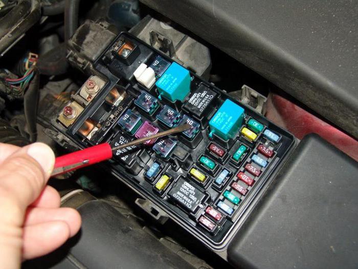
After the cover has been dismantled, the “bonnet” fuse box of the Opel Astra N 2008 and other years of manufacture, on which an integral part is installed, opens up. An open fuse box is an ordered arrangement of fuses and relays. Each element is able to withstand a certain amount of electricity, and is also responsible for the devices of the car.
For ease of identification, each fuse has its own color, depending on how much current it can handle. Based on this, the pinout of the Opel Astra N fuse box is formed.
Layout of relays and fuses in different models car with various configurations will be different. Therefore, before intervening, you need to make sure that the existing scheme fits your Opel Astra N car.

"Distribution" of relays and fuses: the first type of configuration
Fuse box, installed on the Opel Astra N, with basic configuration car protects a number of important elements from failure as a result of a sudden power surge.
Circuit breakers anti-lock braking system able to withstand from 20 to 30 amperes; climate control, as well as the system responsible for heating and ventilation of the passenger compartment of the car, can withstand about 30 amperes. The fan operating in the complex of parts of the cooling system is protected by a fuse that can withstand from 30 to 40 amperes. The central lock withstands 20 amperes.
It is worth noting that the above list does not fully reflect all vehicle systems that are protected by fuses. In order to find out full list, you must carefully study the technical documentation of the car.
Rear fuse box "Opel Astra N"
As mentioned earlier, the Opel Astra N has two safety blocks: in front, in engine compartment car and in the trunk. There are some designations on the fuses and trunk relay that require decoding:
- Heating rear window- KZ X131.
- Terminal 15a - K2 X131.
- Terminal 15 - K1 X131.
A complete decoding of the Opel Astra N fuse box is located in technical documentation vehicle.

Fuse box in trunk
The fuse box in the trunk of the Opel Astra N is located on its left side. In a car with a hatchback body type, you can get to the block by doing the following: the round-shaped locking elements are unscrewed, then the casing cover is lowered. In the sedan is small cap equipped with two handles. You need to pull on them, disconnect the clamps, and lift the cover up.
As with the hood fuse box, the fully equipped vehicle has the largest and most complex fuse box.
How to diagnose fuse performance?
Often in a car, problems begin with electrical equipment, as well as with ignition. One of the causes of the malfunctions is the failure of the fuses. However, before climbing into the safety block and checking the fuses for the fact of operability, it is necessary to check other possible faults: The problem may be a dead battery or a burned out light bulb.
Currently, fuses with a transparent body are used. Thanks to him, you can immediately determine whether the work item or not. If the fusible part of the fuse is melted, then such a device must be replaced immediately. However, on some fuses, this is quite difficult to see, so you should also use a device that will allow you to accurately determine whether the fuse has failed or not.
When checking the performance of fuses, it is necessary to follow a certain algorithm that will significantly save time and effort:
- Visual inspection of the fuse.
- Using a tester and indicator to determine if a fuse is working.
- If the indicator lamp is activated and a short circuit is indicated, the fuse should be replaced: it is in good condition.
- If nothing happened during the check, then the fuse must be replaced.
Checking by the indicator and tester is also carried out in a certain sequence:
- Pull the fuse out of its socket and clean its contacts.
- Study the instructions of the indicator and tester before checking, in accordance with the instructions, connect the fuse contacts. When an indicator appears that reports a short circuit, we can conclude that the fuse is working. When checking the working fuse with an indicator on the device, the light should light up.
- Install a new fuse in place of the blown one. The main condition for replacement is the fact that the characteristics of the new fuse must comply with the recommendations of the automaker.
If there is no special device at hand, then you can always drive the car for an unscheduled inspection. Experts will be able to say with confidence whether replacement of old fuses is really necessary.
What if the problem is not the fuses?
If the checks show that the fuses are operable, and the operability automotive systems has not recovered, then it should be carried out complete diagnostics vehicle in a specialized service center.

Self-intervention in other vehicle systems can lead to quite serious damage: that's when you need a serious overhaul. Many motorists, wanting to save on service inspection and maintenance, trying to figure out a car breakdown on their own, only lose a huge amount of time, and also face huge cash costs.
Precautions when replacing fuses
When there is everything you need to independently find out the cause of a car malfunction, you need to be extremely careful when intervening in the fuse box. After all, their replacement implies the observance of a number of precautions:
- Before opening the lid safety block turn off the engine and switch off the ignition.
- All operations should be carried out carefully.
- Fuses are removed carefully.
- Don't just rely on visual inspection fuse, it must also be checked with instruments.
- Before doing self-diagnosis and replacing fuses, you should carefully study the information about which fuse is responsible for what.
- The new fuse must comply with the requirements and recommendations car manufacturer, which are submitted to technical parameters devices.
The above precautions will allow not only to “bloodlessly” repair the car and replace failed fuses, but also protect the repairer from electric shock, and the car from fire. Ignoring the above recommendations can cause a fire in the vehicle's wiring, as well as enough serious damage from electricity.
At the same time, do not disregard and postpone the replacement of blown fuses. If you drive with defective fuses, then at the next power surge, there is a high risk that the car's systems that were left without protection will fail. And replacing them is much more expensive than replacing fuses.
Conclusion
Summing up the above, it is worth noting that replacing fuses is enough important operation. After all, the performance of all vehicle systems that are “powered” by electricity depends on their performance.
The main reason for the failure of the fuses is a sharp increase in voltage electric current. The fuse blows. Fuses are "consumables", they cannot be repaired, they are replaced.
You can visually diagnose a fuse failure by the fusible element: if it is melted, then a replacement should be made. But visual inspection is best confirmed by using a tester and an indicator. Some fuse models simply cannot be diagnosed by visual inspection alone.
The replacement of fuses is carried out only when it is known which system each fuse is responsible for. This information is in the technical documentation for the vehicle.
Fuses are replaced with care. Failure to do so may result in a fire in the vehicle or severe electric shock.
Do not delay replacing a blown fuse. The next sudden increase in voltage can cause a short circuit and fire the vehicle. The cost of fuses is not particularly high, so you should not save on this small, but sufficient important detail in the electrical system of the vehicle.
Circuit breakers
The marking of the new fuse must match the marking of the defective fuse.
There are three fuse boxes in the car:
■ in the left front of the engine compartment.
■ Behind the storage compartment in the interior of left-hand drive vehicles or, in right-hand drive vehicles, behind the glove box.
■ under the cover on the left wall of the luggage compartment.
Before replacing a fuse, turn off the appropriate switch or switch off the ignition.
A defective fuse can be identified by a burnt fusible filament. Replace the fuse only after the cause of its failure has been eliminated.
Some circuits may be protected by multiple fuses.
In addition, fuses that do not have a specific purpose can be inserted.
Fuse remover
The fuse remover is stored in the fuse box in the engine compartment.


Slide the tool over the fuse from the top or side, depending on the type of fuse, and remove the fuse.
Fuse box in the engine compartment

The fuse box is located in the left front of the engine compartment.
Release the cover latch and lift the cover up until it stops. Remove the cover by pulling it straight up.


After replacing blown fuses, close the cover of the fuse box and fix it by pressing from above. If the fuse box cover is not closed correctly, malfunctions may occur.
Fuse box in dashboard

On left-hand drive vehicles, the fuse box is located behind the glove box on the dashboard. Open the compartment and push left to unlock. Lower the compartment down and remove it.

On right-hand drive vehicles, the fuse box is located behind a cover in glove box. open front glove box, then open the cover and lower it down.


This model has been in production since 2004. For a long time of operation, the owners of this car have accumulated considerable experience in maintenance and repair. When faced with electrical problems, many drivers become lost in electronic systems, wires and connectors. And in this model, finding the cause of an electrical malfunction is not so easy even for trained people, because fuses and relays Opel Astra H vary depending on equipment.
Common problems, ways to fix them and error diagnosis - all this may be needed to fix Astra.
In the base and complete sets fuses and relay Opel Astra H differ in numbering. For example, in the trunk basic version there is a small fuse and relay box, and in full version- complete. Under the hood, the fuse numbering of the basic version does not match the full version. This is due to the difference in electronic components and different electrical circuits.
This article discusses the mounting blocks of a complete set.
Fuses in trunk:
1 (25 A) - power windows in the front doors. If the glass lift of one of the front doors suddenly stops working, first check this fuse, then the wiring at the door opening, between the body and the door.
The wire could break off or oxidize pin connector. Remove the trim from the door and check the wires inside the door. Check ground (brown wire between body and door). At removed skin also inspect the lift drive mechanism and check its motor.
If the power windows do not work correctly, you can program them. To do this, disconnect the battery for a while, reconnect it, turn on the ignition, with the window closed, press and hold the power window up button for 3-5 seconds. Press and hold the button for each door separately.
2 - not used.
3 (7.5 A) - dashboard. If the devices or the backlight of the panel do not work, also check fuse 18. It may be the board of the panel itself or the wiring connector on the back of it.
4 (5 A) - air conditioning system. If the air conditioner does not work, also check fuse 14 in this block and fuses 4, 20, 32 in the engine compartment, as well as relay K8_X125 under the hood. Incorrect settings in the vehicle menu may be set. Try removing the ECO mode, changing the climate control and air conditioning settings.
At negative temperatures, the air conditioner will not turn on due to the low gas pressure in the system, so in winter it is better to turn it on. warm boxes(for lubricating seals). Check the pressure, top up if necessary and check the system for leaks. Check the operation of the clutch and compressor, the serviceability of the A / C button. Exact reason will help determine the diagnosis in the service using a device connected to the diagnostic connector.
5 (7.5 A) - airbags.
6,7,8,9,10 - not used.
11 (25 A) - heated rear window. If the rear window stops fogging or the heating only turns on for a few seconds, also check fuse 18 in this block and relay K3_X131 in the block under the hood.
12 (15 A) - rear window cleaner. If the rear "wiper" does not work, check in addition, prev. 15 in the engine bay. A common problem is moisture getting into the motor mechanism and rear wiper. Due to the formation of rust, some parts may jam.
To remove the mechanism with the motor, you need to remove the tailgate trim, and then the mechanism itself. After removal, check the condition of the shaft by knocking out the sleeve that is put on it. If the shaft is clogged, rusted, or not spinning, knock it out, clean it, and reinstall it.
13 (5 A) - parking assistance system.
14 (7.5 A) - air conditioning system. See prev. four.
15 - not used.
16 (5 A) - passenger detection system on front seat, Open&Start system.
17 (5 A) - tire pressure sensor, rain sensor, air quality sensor, auto-dimming rear-view mirror.
18 (5 A) - devices and switches on the panel. See prev. 3.
19 - not used.
20 (10 A) - shock absorber control (CDC system).
21 (7.5 A) - heated side mirrors. It usually turns on when you press the rear window heating button. If the heating stops working side mirror, check the wiring between the body and the door, as well as in the mirror itself. To do this, remove the trim or the entire mirror and check the contacts in the connector inside it.
Often the lower contacts burn or oxidize. If the heated mirrors do not work together with the rear window heating, also check fuse 11. Photo of the wiring and mechanism inside the mirror with the trim removed:
22 (20 A) - glass sliding roof (motor sunroof). See also prev. 34.
23 (25 A) - power windows of the rear doors. If one of the glasses in rear doors stopped lowering / rising, check the wiring harness that comes out of the body and enters the door. Usually there is a broken brown wire that goes to ground.
Also check the serviceability of the button on the door itself, the motor and the lift mechanism by removing the door trim. It does not hurt to check fuse 1, which is responsible for the operation of the front power windows.
24 (7.5 A) - diagnostic connector. The OBD2 connector is located under the handbrake, hidden behind the shelf cover. To diagnose errors, Tech2, MDI or OP-COM scanners are usually connected.
25 - not used.
26 (7.5 A) - electric folding side mirrors.
27 (5 A) - alarm, ultrasound sensor. In regular Opel alarms Astra H for arming, you need to press the key fob button 2 times, after that the car will arm with a delay of 15 seconds. To simply close all the doors, you need to press the same button 1 time, then the security mode will not turn on. To open or close all windows, you need to press and hold the open / close button, respectively.
28 - not used.
29 (15 A) - cigarette lighter, 12 V socket on the center console. Usually this fuse blows when there is a short circuit in the cigarette lighter socket. If you insert non-standard connectors from appliances into it, make sure that there are no extraneous washers on them that can fly off and short out the contacts. Devices are best connected to an additional 12 V socket (if available) or to a splitter.
30 (15 A) - 12 V rear socket.
31, 32 - not used.
33 (15 A) - Open & Start system.
34 (25 A) - glass sliding roof (electric sunroof). See also prev. 22.
35 (15 A) - 12 V rear socket.
36 (20 A) - socket for connecting a trailer, towing device.
37 - not used.
38 (25 A) - central locking, output "30". For problems with the alarm, see 27. If the central locking stops closing the doors, check if the interior light is on. If it is on, most likely the limit switch in one of the doors has failed and the unit “thinks” that one of the doors is open. This usually triggers an alarm.
In case of problems with central lock you can try to throw off the battery terminal for a while and connect it back. To determine the exact cause, you can diagnose using the methods described at the end of the article or in a car service when connecting the device to the diagnostic connector.
39 (15 A) - heated driver's seat.
40 (15 A) - seat heating front passenger
. If the seats stop heating when this feature is enabled, check the connectors and wires underneath.
41, 42, 43, 44 - not used.
Relay in trunk:
K1_X131 - ignition lock relay, output "15".
K2_X131 - ignition lock relay, output "15A".
K3_X131 - rear window heating relay. See prev. eleven.
Fuses in the box under the hood:
The engine compartment mounting block is located on the left driver's side, under the hood between the pillar support and the left headlight. To get to it, you need to open the lid by prying it around the edges.
1 (20 A) - anti-blocking ABS brakes
.
2 (30 A) - ABS anti-lock brakes. If the ABS light on the panel comes on and this system stops working, check and clean ABS sensors and speed sensors at the front and rear wheels, their wiring and connectors. It could also be the ABS control unit. A more accurate reason can be said by the result of diagnostics by the device.
Usually, problems with ABS occur after replacing the wheel hubs or their bearings; when assembling the units, the sensors or their connectors are not installed correctly, which leads to chafing of the wires or lack of contact.
3 (30 A) - stove fan (climate control).
4 (30 A) - stove fan (air conditioner). If the stove stops working, the fan itself may be clogged, its motor or thermal fuse has blown. Clogging is especially likely if the stove has not been serviced for a long time (several years). Disassemble the stove, clean all components and lubricate the fan axle and bearings.
To get to the stove, you need to remove the glove box. If the stove only works in the last maximum position, you need to change the resistor. It could also be the climate control unit or the air conditioner. If the stove blows cold air, check the level of antifreeze and the presence of air in the cooling system.
5 (30 or 40 A) - radiator fan.
6 (20, 30 or 40 A) - radiator fan motor. If the cooling fan has stopped turning on, check the health of its engine by applying voltage from the battery directly. If the motor does not work, remove it, disassemble and clean, checking the brushes or replace with a new one. The case may be in the electronic control unit, temperature sensor, thermostat or wiring. Proper diagnosis will reveal the exact cause.
7 (10 A) - front and rear windshield washers. If the washer stops working when it gets cold, check the fluid level in the washer reservoir to see if it has frozen in the pipes and nozzles. Reheat if necessary and change. Also check the serviceability of the pump-pump in the tank by applying 12 V voltage and wiring to it.
8 (15 A) - sound signal . If the signal stopped working, most likely the matter is in the CIM module, steering column cable and its connector. In this case, the buttons located on the steering wheel (for example, the volume) usually stop working. A common problem. If the matter is in the SIM module, soldering the contacts on its board, repairing broken wires, or replacing it with a new module usually helps.
9 (25 A) - front and rear windshield washers. See above prev. 7.
10, 11, 12 - not used.
13 (15 A) - fog lights. If not working, check bulbs, connectors and wiring.
14 (30 A) - cleaners windshield
. If the “wipers” do not work, the mechanism in the gear motor or the wire contacts is most likely clogged or frozen. Take it apart and clean it. Also check the motor brushes.
Setting the interval for the operation of the wipers in intermittent mode: press the “wipers” lever down to operate them, wait for the required time and turn on the intermittent operation of their operation (switch the lever up). The cleaners will now run at the set interval. Valid values are 2-15 seconds.
15 (30 A) - rear window cleaner. See prev. 12 in the trunk block.
16 (5 A) - Open & Start system, opening roof, ABS, brake light switch.
17 (25 A) - heating fuel filter(only for diesel engines).
18 (25 A) - starter. If it doesn’t turn, check the K1_X125 relay, the battery charge, the contacts of its terminals, the negative contact on the car body, the serviceability of the starter itself, the retractor relay and the wiring / connectors. If automatic transmission, check its selector, serviceability of the brake pedal switch. Diagnostics will indicate the exact cause.
19 (30 A) - electronic systems gear boxes.
20 (10 A) - air conditioning compressor. See prev. 4 in the luggage block.
21 (20 A) - engine electronic systems.
22 (7.5 A) - engine electronic systems.
23 (10 A) - headlights, adaptive light (AFL system), electric tilt angle corrector. If the near or high beam check and replace the lamps. To replace a bulb in one of the headlights, turn the wheels in opposite side, open a special hatch located in the wheel arch, remove the rubber boot from the headlight through it, remove the old lamp by turning it counterclockwise and install a new lamp by turning clockwise to lock into the slot.
To turn on the "road home" mode of the headlights, you need to turn off the ignition and remove the key from the lock, open the driver's door and blink high beam(short press of the lever). After that, when closing driver's door dipped beam + flashlight will be turned on reversing, which will automatically turn off after 30 seconds.
24 (15 A) - fuel pump . If the pump does not pump gasoline and the engine does not start, check the wires under the hood in the corrugation between the engine control unit and the fuse box. Usually they are frayed there or the contact disappears in the connectors for connecting to these blocks. The exact cause can be determined by diagnostics and reading errors.
25 (15 A) - electronic systems of the gearbox.
26 (10 A) - engine electronic systems.
27 (5 A) - electric power steering. If the steering wheel began to turn hard, check the power fuse FB3, the oil level in the power steering reservoir. The reservoir is under the hood passenger side, in a recess near the windshield.
If the steering wheel turns tightly only in the cold, it works normally when it warms up, most likely the oil in the power steering system freezes, replace the oil with a more temperature-resistant one. In case of problems with oil, it may fail or jam steering rack. The pump could also fail, in this case, either repair or replace with a new one.
28 (5 A) - electronic transmission systems.
29 (7.5 A) - electronic transmission systems.
30 (10 A) - engine electronic systems.
31 (10 A) - headlights, adaptive light (AFL system), electric tilt angle corrector. See prev. 23.
32 (5 A) - air conditioning, clutch pedal switch, malfunction lamp in the brake system.
33 (5 A) - outdoor lighting (control unit), headlights, adaptive light (AFL system), electric tilt angle corrector.
34 (7.5 A) - steering module (control unit).
35 (20 A) - information and entertainment system.
36 (7.5) - Twin Audio system, display, radio, mob. telephone.
Relay in the block under the hood:
K1_X125 - starter relay. See prev. 18 in the block under the hood.
K2_X125 - relay electronic block engine control (ECU).
KZ_X125 - output "5".
K5_X125 - relay operating modes of the windshield wiper.
K6_X125 - relay front wiper . See prev. 14 in the block under the hood.
K7_X125 - headlight washer relay (pump). If it does not work, check the fluid level in the washer, as well as the absence of blockages and freezing in the pipes and nozzles.
K8_X125 - air conditioner compressor relay.
K10_X125 - fuel pump relay. See prev. 24 in the block under the hood.
K11_X125 - radiator fan relay.
K12_X125 - radiator fan relay.
K1Z_X125 - radiator fan relay. See prev. 5 in the block under the hood.
K14_X125 - fuel filter heating relay (only for diesel engines).
K15_X125 - stove fan relay. See prev. 3 in the block under the hood.
K16_X125 - relay fog lights . See prev. 13 in the block under the hood.
Power fuses in the engine compartment of the Opel Astra H:
The power fuse box is located under the hood, next to the main fuse box, between it and the left pillar support. To get to it, you need to open the lid.
FB1 (50 A) - electro-hydraulic hard top HT.
FB2 (80 A) - glow time controller (diesel engine only).
FB3 (80 A) - electro-hydraulic power steering. See prev. 27 in the block under the hood.
FB4 (30 A) - autonomous heater IH.
FB4 (100 A) - optional electric heater in the salon EH.
FB5 (80 A) - fuse and relay box in the trunk.
FB6 (80 A) - fuse and relay box in the trunk.
Error diagnostics:
To determine the cause of the malfunction, you can diagnose the system without a special device using the methods described below.
For manual transmissions or Easytronic:
- while continuing to hold the pedals, wait a few seconds until the display shows on-board computer error messages
For automatic transmissions:
- insert the key into the ignition
- turn the key, turning on the ignition, but not starting the engine
- depress the brake pedal and keep it pressed
- shift gear lever to position D
- turn off the ignition, release the brake pedal
- depress the accelerator and brake pedal at the same time and hold them down
- turn the key, turning on the ignition, but not starting the engine
- while holding the pedals, wait a few seconds until messages appear on the on-board computer display
In diagnostic mode, the ECN message with error codes will appear on the display. 4 digits - error code, 2 digits - value.
The fuse box in the car is important element ensuring the good condition of all electrical mechanisms. Each fuse on the Opel Astra G is responsible for a specific section of the electrical circuit. The burnout of this part is a signal of a malfunction or improper operation of the machine components.
[ Hide ]
Location and wiring diagram
Circuit breakers car Opel Astra G are located in separate mounting blocks of the electrical system, which are installed in the instrument panel and engine compartment. AT last block fusible links and relay mechanisms for the most loaded in terms of current strength are placed electrical circuits. This position safety elements makes it possible to provide reliable performance car electricians. Both blocks in cars before 2001 and later have differences in the location of the components. The designation of fuses and relays is printed on the wiring diagram located on the back cover cabin block.
Scheme of installation of elements in the cabin block
On Astra cars manufactured in 1998, 1999 and 2000, on the left side of the block located under the hood, there are sockets F1-F5 for more powerful fuses. To the right - two rows of vertically installed fuse-links marked F6-F23 and F24-F41. Above the fuse slots there are regular places for spare parts and plastic pliers that are used when replacing parts. In the same block, there are eight more fuse-links, which are the same for all Opel cars Astra G and arranged vertically in a row.
Fuses and relays are installed in the mounting block located in the cabin. The fuses are rated from 7.5 to 40 amps and are located in two rows at the bottom of the block.
Layout of the relay in the early block The wiring diagram of the early version of the cabin unit, the fuse locations are circled in red, the places for spare inserts and plastic tongs are circled in green Block of machines from 2001 with fuse designation wiring diagram relay in late block
Fuse decoding
A complete description of the Opel Astra G fuses is given in the tables in the photo.
Fuses in the old block, part 1 Fuses in the old block, part 2 Fuses in the old block, part 3 Fuses in the new block, part 1 Fuses in the new block, part 2 Fuses in the new block, part 3
The purpose of the eight fuses in the block under the hood of the car is as follows (from top to bottom, using the example of a 2003 car):
- 1 (60 A) - ignition switch circuits;
- 2 (60 A) - general protection of the fuse box in the cabin, engine control mechanism;
- 3 (60 A) - relay in the dashboard of the car;
- 4 (40 A) - protection of electric motors of the cooling and air conditioning system from short circuit;
- 5 (60 A) - ABS block;
- 6 (30 A) - circuits of engine control units (gasoline pump, injection system, ignition, etc.);
- 7 (80 A) - power steering;
- 8 (40 A) - protection of electric motors of the cooling and air conditioning system from short circuit (only on machines with air conditioning).
Relay type and purpose
Relay decoding mounting block early sample is as follows:
- 1 - encoding connector;
- 2 - horn relay;
- 3 - switching on the high beam;
- 4 - rear wiper activation relay;
- 5 - heated mirrors;
- 6 - turn on the front fog lights;
- 7 - activation of the rear fog lamp;
- 8 - right direction indicators;
- 9 - left direction indicators;
- 10 - built-in telephone relay;
- 11 - reserve;
- 12 - front wiper activation relay;
- 13 - reserve;
- 14 - power supply for rear window heating.
The turn signal relay can be made in a common housing or in separate parts.
The video from kivalssl1 shows the installation of the "comfort" block relay in the Astra G mounting block.
On models 2001, 2002, 2003, 2004 and the following years of release, the purpose of the relay has slightly changed. Relay 11 was added, which is responsible for transmitting signals from wheel rotation sensors and relay 13 for interior lighting. On the side, a “comfort” device is inserted into the mounting block, indicated in the diagram by the number 15.
Below is the designation of several more relays in the engine compartment block.
How to replace yourself?
To replace elements in the interior mounting block, it is not required special tools. All you need is a slotted screwdriver and a set of new fuses.
Replacing fuses
A guide to replacing failed fuses, for example, those responsible for the operation of the stove or cigarette lighter, is as follows:
- Turn off the vehicle's ignition system.
- Open a small folding box on the instrument panel, located in the area of \u200b\u200bthe knee of the driver's left leg.
- Press the plastic clips located on the sides and remove the box body from the frame.
- Unscrew the four slotted screws securing the frame.
- Remove the mounting block from its place by pulling on the bottom.
- Replace defective fuse. To do this, the damaged fusible element must be removed from the socket. There are small plastic tongs included with the mounting block. They need to clamp the fuse case, pull it out with seat and insert a new part.
- Visually check the condition of the remaining fuse links.
- Perform reassembly.
It is important to note that the new fuse must have the same rating as the failed fuse. In the absence of such a detail, an element of a slightly larger value can be used. Just need to check first working condition circuit, for this you should install a fuse from any other socket with the required rating. If the fuse remains intact, then a part with a higher rating should be put in its place. But at the first opportunity, it should be replaced with a part with a regular rating. Because long-term operation an incorrect fuse can damage the vehicle's electrical systems and cause a fire. If, after replacing the fuse, it immediately fails, then it is necessary to find out the cause of the overload in the electrical circuit.
The process of changing fuses on more modern Opel Astra H 2008 or Opel GTC 2012 is identical to the above.
Replacement parts in engine compartment even simpler. To do this, unfasten the plastic covers of the blocks and change the damaged fuses or relays.
Removing the relay box cover Removing the fuse box cover
Block replacement
During the operation of the car, situations may arise in which the mounting blocks are severely damaged. In this case, the owners are forced to change the entire blocks, buying new parts or using those removed from other machines.
This replacement requires experience with electrical systems, as well as various tools and devices, so this procedure is best done in a specialized workshop.
But in the case when it is decided to replace the block inside the cabin with your own hands, the sequence of actions will be as follows:
- De-energize the car by turning off battery. Before this, you need to make sure that the code for the standard audio system is saved.
- Get access to the mounting block by analogy with the procedure for replacing fuses.
- Disconnect the pads and wires from the old block.
- Visually compare the appearance of the old and new unit, check the identity of the fuse and relay ratings.
- Install the new mechanism in place, making sure that the colors of the cables match.
- Connect the power to the car and check the functionality of the systems.
- In the event of inoperability of components or blown fuses, it is necessary to find out the causes of the problems.
Opel Astra N. Location of fuses, fuses and relays and their replacement
Most vehicle electrical power circuits are protected fuses. headlights, fan motors, fuel pump and other powerful current consumers are connected via a relay. Fuses and relays are installed in mounting blocks, which are located in the trunk of the car under the sidewall lining on the left side and in the engine compartment next to the battery.
The designations of the fuses and relays of the mounting block installed in the trunk under the lining of the left sidewall are shown in fig. 10.1.
In table. 10.1 indicates the purpose of these fuses, fuses and relays, but on a particular car model, some of the circuits indicated in the table may not be available.
The designations of the fuses and relays of the mounting block installed in the engine compartment on the right in the direction of travel are shown in fig. 10.2.
In table. 10.2 indicates the purpose of these fuses, fuses and relays, but on a particular car model, some of the circuits indicated in the table may not be available.


1. To gain access to the editing fuse box located in the trunk, rotate the two locks of the hatch cover in the upholstery of the left side panel by 90 ° ...

2….and flip down the cover.

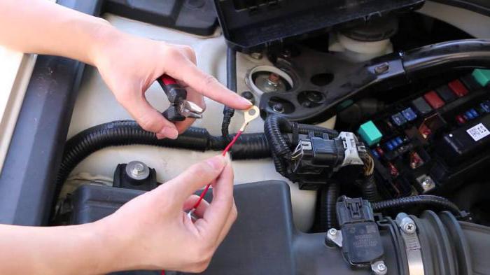
3. To gain access to the mounting block located in the engine compartment, press the two latches with a screwdriver ...

4….and remove its cover.
Note.

Spare fuses B and tweezers A are fixed in special sockets of the body of the mounting block located in the trunk to remove the fuses from the mounting blocks.
5. Before replacing a blown fuse or fuse, find out the cause of the blown and fix it. When looking for a malfunction, look at the ones listed in Table. 10.1 and 10.2 circuits that this fuse or fuse protects.
Warning.
Do not replace fuses with fuses of a different amperage or homemade jumpers, as damage may result. electrical appliances and even fire.

6. Remove the tweezers from the base of the mounting block located in the trunk.

7. Grab the fuse with tweezers ...

8….and remove it from the connector.
Note.

This is how a blown fuse looks like (the jumper shown by the arrow inside the holder has blown and opened). To replace a fuse, use a spare fuse of the same rating (and color).

9. Install a fuse of the same rating as the removed one into the connector.

10. If replacement is necessary, remove the relay from the mounting block by rocking it from side to side ...

11….and install a new relay.