Details and service of the control drive of the YaMZ gearbox of cars Maz-5516, 5440
The gearbox drive of Maz-5516, Maz-5440, 64229, Maz-54323, 54329 and YaMZ-239 vehicles is shown in Figure 4.
During operation, if necessary, the following adjustments of the gearbox drive are made:
The procedure for adjusting the control of the YaMZ-239 gearbox for Maz-5516, Maz-5440, 64229, Maz-54323, 54329 cars is as follows:
Set lever 2 to neutral position;
By longitudinal movement of the plate 16 with the bolts 17 released, set the angle a of the lever 1;
By changing the length of the rod 3, set the angle.
In case of insufficient travel of the plate 16 or the range of adjustment of the thrust 3, loosen the bolts 5, move or rotate the thrust 6 relative to the shank 4, tighten the bolts 5 and repeat the adjustment of the angles a, b as described above.
Angle a should be 80 °, angle b 90 °.
Adjustment of the blocking device of the telescopic elements of the box transmissions YaMZ-239 cars Maz-5516, Maz-5440, 64229, Maz-54323, 54329 to produce with the raised cabin as follows:
Undo the pin 8 and disconnect the rod 6 from the fork 9 of the gearbox drive lever;
Push the inner rod 6 up to the stop of the projections of the earring 12 into the grooves of the tip 15;
Keeping the mechanism compressed, screw in the shank until the mechanism is locked by the sleeve K) under the influence of the spring 11:
Tighten the lock nut 13, check the accuracy of the locking mechanism. When the mechanism is locked, the axial and angular backlash should be minimal.
In the unlocked position, the sleeve 10 is shifted to the left. The movement of the extension should be smooth, without jamming, and the locking mechanism should ensure that the extension rod is firmly locked in its original position.
When connecting rod 6 to fork 9, the hole in the shackle for pin 8 must be located above the longitudinal axis of rod 6. Adjust the drive with the engine off.
When the cab is lifted, oil under pressure from the cab lifting pump is supplied through the hose 7 to the cylinder of the locking device and the mechanism 6 is unlocked.
After lowering the cab, to securely fix the telescopic mechanism 6 in the locked position, it is necessary to move the gear shift lever 1 forward in the direction of the vehicle in a movement similar to engaging a gear.
In this case, the mechanism is blocked and is subsequently ready for operation.
Scheme of gear shifting of the check point of cars Maz-5516, Maz-5440, 64229, Maz-54323, 54329 and YaMZ-239, see Figure 5.
Fig. 4. Gearbox control drive YaMZ cars Maz-5516, 64229, Maz-54323, 54329
1 - lever; 2 - lever; 3.4 - thrust; 5.17 - bolt; 6 - thrust (telescopic mechanism); 7 - hose; 8 - finger; 9 - plug; 10 - bushing; 11 - spring; 12 - earring; 13 - lock nut; 14 - shank; 15 - tip; 16 - plate; 18 - switch
Gearbox control drive for cars Maz-5516, Maz-5440, 64229, Maz-54323, 54329 with MAN engine
When controlling the gearbox of cars Maz-5516, Maz-5440, 64229, Maz-54323, 54329, be guided by the following:
The control of the main gearbox and the demultiplier is carried out using the gearbox lever according to the diagram shown in Figure 19 (gearbox ZF).
The transition from the slow range to the fast range is carried out by moving the lever in the neutral position away from you, overcoming the force of the retainer, from the fast range to the slow range - in the reverse order.
The divider is controlled by a flag on the gear lever handle. The transition from the slow range (L) to the fast (S) and vice versa is carried out by pressing the clutch pedal all the way after the flag is moved to the appropriate position. Switching is possible without disabling the transmission in the main gearbox.
Adjustment of the gearbox control drive of the gearbox of cars Maz-5516, Maz-5440, 64229, Maz-54323, 54329
During operation, if necessary, the following adjustments of the gearbox drive of Maz-5516, Maz-5440, 64229, Maz-54323, 54329 cars are made for MAN engines:
Adjusting the position of the lever in the longitudinal direction;
Adjusting the position of the lever in the transverse direction;
Adjustment of the locking device of the telescopic drive elements.
Adjustment of the position of the lever 1 (Figure 7) in the longitudinal and transverse directions is carried out by moving and rotating the rod 5 in the shank 6 with the bolts 7 released.
In this case, the angle a should be 85 °, the angle e = 90 °. The angle a can also be adjusted by moving the plate 3 with the bolts 2 released.
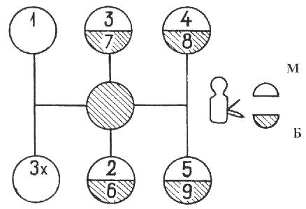
Fig. 5. Scheme of gear shifting of the check point of cars Maz-5516, Maz-5440, 64229, Maz-54323, 54329, YaMZ-239
M - slow range; B - fast range.
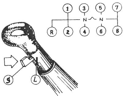
Fig. 6. Scheme of gear shifting of the gearbox ZF of cars Maz-5516, Maz-5440, 64229, Maz-54323, 54329
L - slow range; S - fast range.
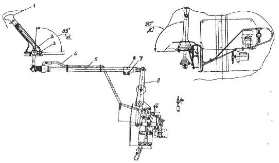
Fig. 7. Gearbox control drive for cars Maz-5516, Maz-64229, Maz-54323, 54329
1 - lever; 2, 7 - bolt; 3 - plate; 4 - hose; 5 - intermediate mechanism; 6 - shank; 8 - growl
The gearbox drive of Maz-5440 vehicles is shown in Figure 8.
Switching of the main box is made by lever 1 of the mechanism remote control... The additional box is controlled by the range switch 18 located on the gear shift lever 1.
When the range switch is in the lower position, the fast range is turned on in additional box, at the top - the slow range.
During operation, if necessary, the following adjustments are made to the gearbox of Maz-5440 vehicles:
Adjustment of the angle of inclination of the lever 1 in the longitudinal direction;
Adjustment of the angle of inclination of the lever 1 in the transverse direction;
Adjusting the telescopic locking device. To adjust the angle of inclination of the lever in the longitudinal direction:
Set lever 2 to neutral position by tightening the lock neutral position on the switching mechanism 20 (for KP YaMZ - 238M).
Check the neutral position of the gearbox of the gearbox of Maz-5440 cars by moving the roller of the lever 2 in the axial direction by pressing it by hand. In this case, the roller should move by an amount of 30 - 35 mm;
Loosen the tightening of the bolts 17 and by longitudinal movement of the plate 16 set the angle "a" to 90 degrees;
If the travel of the plate 16 is insufficient, loosen the bolts 5, move the rod 6 relative to the shank 4, tighten the bolts 5 and repeat the adjustment of the angle "a" by moving the plate 16.
Adjustment of the lever 1 in the transverse direction is carried out by changing the length lateral thrust 3 by detaching one of the lugs with unscrewing the nut of its fastening, followed by adjusting the length so that the lever 1 takes a vertical position.
After adjustment, return the neutral position lock to its original position (for the YaMZ-238M gearbox).
Adjustment of the locking device of the telescopic gearbox of the Maz-5440 vehicles should be done as follows:
Unpin the pin, unscrew the nut, remove the pin and disconnect the rod 6 from the fork 9 of the gear lever;
Loosen the lock nut 13 and unscrew the shank 14 up to the thread stop;
Push the inner rod 6 up to the stop of the earring projections into the grooves of the tip 15;
Keeping the mechanism compressed, screw in the shank 14 until the mechanism is locked by the sleeve 10 under the influence of the spring 11;
Tighten the lock nut 13, check the accuracy of the locking mechanism. When the mechanism is locked, the axial and angular backlash should be minimal. In the unlocked position (bushing 10 is shifted to the right), the internal link should be pushed out by the return spring by 35 - 50 mm.
Further movement of the extension should be smooth, without jamming and the locking mechanism should ensure that the extension rod is clearly fixed in its original position.
Avoid bending and bending of the drive rod and its telescopic components. Adjust the gearbox drive with the engine off.
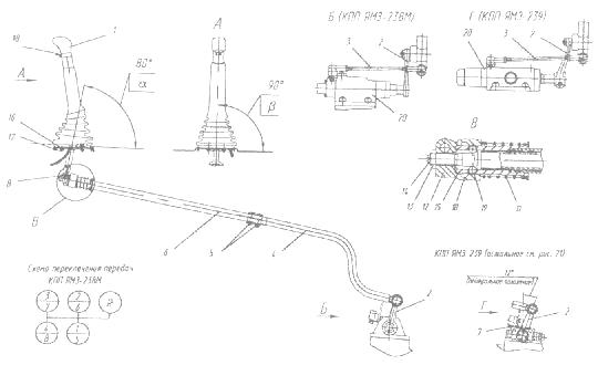
Fig. 8. Gearbox control drive for cars Maz-5440
1,2 - lever; 3, 4, 6 - thrust; 5, 7, 17 - bolt; 8 - finger; 10 - bushing; 11 - spring; 12 - earring; 13 - nut; 14 - shank; 15 - tip; 16 - plate; 18 - switch 19 - ball; 20 - switching mechanisms.
_________________________________________________________________________________________
- Service of the fuel system of the diesel engine D-245
_________________________________________________________________________________________
- Operations for the assembly of the basic components of the ZIL-130 engine
_________________________________________________________________________________________
Gearbox of MAZ and URAL vehicles
TO Category:
Car chassis
Gearbox of MAZ and URAL vehicles
On a MAZ-500 car equipped with a YaMZ-236 diesel engine, installed five stepped box gears with overdrive and remote mechanical control... The inclusion of the second - third and fourth - fifth gears is carried out using two synchronizers.
Primary shaft with a gear is installed in a crankcase on a ball bearing. Intermediate shaft also installed in the crankcase: at the front on a cylindrical roller bearing, and at the rear on a ball bearing. Nest rear bearing closed with a cast iron lid.
The gear wheel of the first gear and reverse gear is cut directly on the shaft, and the gear wheels of the second gear, third, fifth, the power take-off gear and the drive gear are fixed on the shaft on keys. Drive gear intermediate shaft equipped with a damper (damper), which reduces vibrations transmitted from the engine to the gearbox, and the noise of gears when the diesel engine is running on Idling... The need to install a damper is caused by the insufficient uniformity of the YaMZ-236 diesel engine.
The gear rim of the gear is made separately from its hub and is connected to the hub through six coil springs. The vibrations transmitted to the ring are damped in the gear due to the deformation of the springs and friction in the damper elements.
An axle is fixed on the side between the intermediate and output shafts, on which a double intermediate reverse gear is mounted on two roller bearings. The front gear is meshed with the first gear of the intermediate shaft, and the gear engages with the rear gear when reverse is engaged.
The front end of the output shaft is mounted on a roller bearing in a groove input shaft, and its rear end is in the crankcase on a ball bearing. On the outwardly protruding end of the shaft, a speedometer drive gear and a flange are fixed cardan joint... The rear bearing is closed by a cover in which the driven gear wheel of the speedometer drive and the oil seal are installed. On the rear part of the shaft, which has splines, there is a movable gear wheel for engaging the first gear and reverse. The gear has straight teeth.
On the secondary way, gears are freely mounted on steel plain bearings of a special design: - second gear, - third gear and accelerating fifth gear. The gears are protected from longitudinal displacement by thrust rings. These three gears have helical teeth and are permanently meshed with the countershaft gears. On gears, as well as on gears input shaft, s the ends have a tapered surface and internal teeth.
Synchronizers are located between the gears of the second and third gears and the gears of the fifth gear and the input shaft, which provide silent switching of the second, third, fourth and fifth gears.
The synchronizer consists of a coupling mounted on the splines of the shaft (front synchronizer) or on the splines of the sleeve fixed on the shaft (rear synchronizer), and a housing with bronze tapered rings. The body is connected to the coupling by means of ball clamps. The clutch has toothed rims. The clutch pins pass through the shaped slots of the body, and a ring is attached to them from the outside with the help of pins, into the groove of which the switching fork enters.
Rice. 1. Gearbox of the MAZ-500 car
In this case, the tapered body ring is pressed against the pinion cone. Due to friction between the tapered surfaces, the body turns and falls by the groove of the slot on the coupling pin, blocking it with the body. As a result, the housing cone is strongly pressed against the gear cone by the force applied to the gear lever. Due to the resulting strong friction between the speed cones, the gears and couplings are aligned with the shaft, and the locking device releases the coupling from the synchronizer housing. The clutch, squeezing out the balls of the retainers, moves further. In this case, its gear rim engages with the internal teeth of the gear, including the transmission.
Three switching rods are installed in the crankcase cover tide drips. The forks of the rods are connected to the carriage for engaging the first gear and reverse gear and with two synchronizer couplings. The switch rods are equipped with ball locks and locks.
The heavily loaded gearbox bearings are pressure lubricated. Oil from the box crankcase through a detachable filter equipped with a magnet is sucked through the channel by a gear pump driven from the front end of the intermediate shaft and is pumped through the channel in the crankcase and cover and through the channel in the primary and secondary shafts to the bearings of the gears of the secondary shaft, to its front bearing and on the drive gears. All other parts are lubricated with splash oil.

Rice. 2. Details of the gearbox synchronizer of the MAZ-500 car, the diagram of its operation
The oil pump has a pressure reducing ball valve that limits the oil pressure in the transmission lubrication system.
The gearbox housing has a baffle inside, so two holes are made to drain the oil, closed with plugs.
Gear shifting is carried out by a lever located in the cab using a mechanical remote drive, the need to use which is caused by the forward displacement of the cabin located above the engine. In the bracket, fixed on the tide of the gearbox housing cover, a gear shift roller is installed on two supports. At the inner end of the roller, a shift lever is fixed, the end of which enters the grooves of the grooves attached to the shift rods. In the middle position, the lever is installed with an upper retainer with a pin and a spring and a lower retainer for a reverse safety lock with two pins and a spring. The outer pin is installed in the swinging leash for switching the first gear and reverse. The leash is pivotally mounted on a pin fixed in the tide of the gearbox cover.

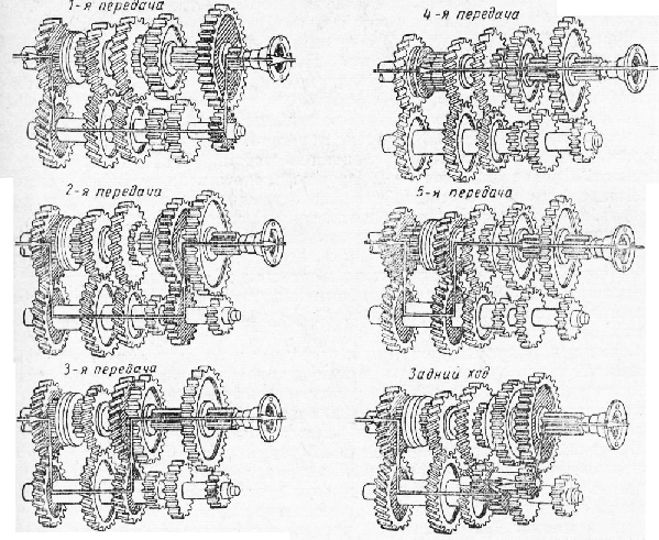
Rice. 3. Diagrams of the positions of the gear lever and the operation of gearboxes of MAZ n KrAZ vehicles
At the outer end of the roller, a second lever is fixed, which enters with its end into the head of the movable rod installed in the bracket tide. The outer end of the movable rod with a long rod with cardan joints is connected to intermediate mechanism control, the bracket of which is fixed to the vehicle frame. The lower end of the gear lever is connected to the outer end of the transverse roller of this mechanism by means of a cardan joint. The lever passes through the support in the cab floor. This design of the lever allows the cab to be tilted without disturbing all the connections of the transmission control drive. Scheme of gear engagement in the box and the position of the lever when turned on different gears are shown in Fig. 3, a.
A gearbox is installed on the MA3-2G0 car, which has a device and principle of operation similar to the device and principle of operation of the gearbox of the MAZ-500 car. The drive gear of the intermediate shaft does not have a damper. The gears of the second, third and fifth gears are mounted on the output shaft on needle bearings. The gear lever is located on a ball joint in a bracket fixed directly to the gearbox cover. There is a reverse gear safety lock on the lever. On some car models, it is made in the form of a pin with a spring and is installed in the socket of the arm ball joint. A diagram of the positions of the gear shift lever is shown in Fig. 3, b.

Rice. 4. Gearbox of the MAZ -200 car
On cars Ural-375 and Ural-377, a gearbox is installed, which has the same device as the gearbox of the MAZ-200 car (on the first releases) or the YMZ-236S type gearbox (on the latest releases).
TO Category: - Car chassis
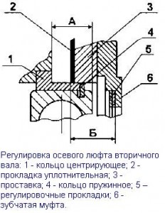
When installing the bearing cover of the input shaft (Fig. 1), the demultiplier with a spacer on the main box crankcase (Fig. 2), the rear bearing cover of the output shaft of the range (Fig. 3), ensure the minimum axial backlash of the shafts using shims selected as follows:
Measure the dimension "A" of the depth of the bearing bore in the bearing cap, taking into account the thickness of the gasket, with an accuracy of 0.1 mm (Fig. 1).
Measure dimension "B" from the end of the outer ring of the bearing to the surface of the crankcase wall with the bearing pressed against the stop with an accuracy of 0.1 mm.
Select the total nominal thickness of the shims S from the condition: S = [A - B - (0.2 ... 0.3)] mm
|
|
 Rice. 2
Measure dimension "A" (Fig. 2) from the end of the outer ring of the bearing to the surface of the crankcase with an accuracy of 0.1 mm, making sure that the centering ring is pressed against the stop, and the snap ring and bearing are firmly pressed against the center ring.
Measure the dimension "B" of the depth of the bearing groove in the gear coupling, taking into account the spacer and the groove with an accuracy of 0.1 mm.
Select the total thickness of the shims S from the condition S = [B - A - (0.2 ... 0.3)] mm
|
|
 Rice. 3
Measure dimension "B" (Fig. 3) from the end of the outer ring of the bearing to the surface of the crankcase with an accuracy of 0.05 mm, making sure that the snap ring and the bearing are firmly pressed against the surface of the crankcase.
Measure the dimension "D" from the gasket to the thrust ring in the cover recess with an accuracy of 0.05 mm.
Select the total nominal thickness of the shims S from the condition: S = [G - B - (0.15 ... 0.2)] mm
Tighten the range-multiplier crankcase mounting bolts in two steps (see the "Tightening torques" table).
|
|
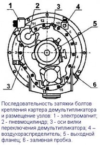
Tightening sequence according to fig. 4.
When repairing the range multiplier with replacing the synchronizer parts, adjust the required stroke length when the upper range is turned on, ensuring the unloading of the fork crackers when operating at the higher range, for which:
1. Turn on the high range in the range multiplier by supplying air under pressure from 784 to 833 kPa (8 ... 8.5 kgf / cm 2) into the rear cavity of the pneumatic cylinder, make sure that the high range engagement clutches are fully engaged. When fully engaged, the indicator lamp should go out the mounting flange cardan shaft should not be rotated by hand force.
2. Wrap up adjusting bolt until it stops in the piston rod (when the bolt rotates, an increase in the resistance to rotation should be felt). Repeat the operation several times, making sure that the stop is felt at the same position of the bolt head.
3. Turn the adjusting bolt from the position of its stop to the end one turn (5 edges of the head) and while holding it in this position, lock it with a lock nut, tightening it with a torque of 137-157 N · m (14-16 kgf · cm). After adjustment, the propeller shaft mounting flange should turn easily without jamming, by hand. Turn the flange through an angle of at least 360˚.
Attention! Incorrect adjustment causes overload of the range fork crackers, which leads to their rapid destruction.
4 Install the range multiplier on the gearbox with the vertical position of the axes of the main gearbox shafts. The output shaft of the range multiplier must be cranked by hand with any range on and off in the main gearbox.
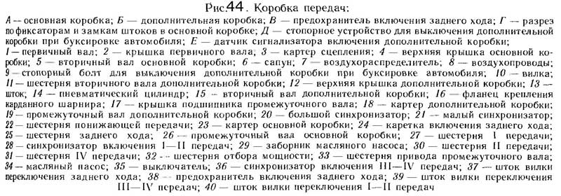
MAZ vehicles are equipped with an eight-speed dual-band gearbox YaMZ-238A with synchronizers in all gears, except for reverse. The gearbox consists of a main two-stage gearbox and a two-stage auxiliary gearbox (reduction gear).
The gearbox arrangement is shown in fig. 44. Installation of all parts of the gearbox is carried out in the housings of the main and additional boxes, which are interconnected, and then assembled to the clutch housing; a single power unit as part of the engine, clutch and gearbox.
The input shaft 1 of the main box is mounted on two ball bearings; driven clutch discs are installed at the front spline end, and the rear end is made in the form of a gear rim of a gear wheel of constant engagement of the main box.
The secondary shaft 5 of the main box at the front rests on a cylindrical roller bearing installed in the bore of the drive shaft gear rim, and at the back - on a ball bearing installed in the front wall of the additional box crankcase. The rear end of the secondary shaft is made in the form of a toothed rim, which is a constant mesh gear of an additional box.
The gears of the second and fourth gears of the secondary shaft of the main box are mounted on plain bearings made in the form of steel bushings having special coating and impregnation, and the first gear and reverse gears are on roller bearings.
The intermediate shaft 26 of the main box at the front is supported by a roller bearing mounted in the front wall of the main box crankcase, and at the rear - on a double-row spherical bearing located in a glass installed in the rear wall of the main box crankcase. In the tides of the crankcase of the main box, an additional axle is installed for the intermediate reverse gear. The reverse is activated by moving the reverse carriage 24 forward until it is connected to the ring gear of the reverse gear 25, which is in constant engagement with the intermediate reverse gear.
The secondary shaft 15 of the additional box at the front rests on a cylindrical roller bearing located in the bore of the gear rim of the secondary shaft of the main box, at the rear - on two bearings: a cylindrical roller bearing and ball bearing, installed respectively in the rear wall of the crankcase of the additional box and the bearing cover of the output shaft.
On the splines of the middle part of the secondary shaft of the additional box, gearshift synchronizers are installed, and at the rear splined end there is a propeller shaft mounting flange. On the middle cylindrical part of the shaft on roller cylindrical bearings, gear 11 of an additional box is installed.
The intermediate shaft 19 of the additional box at the front rests on a cylindrical roller bearing installed in the front wall of the crankcase of the additional box, and at the rear - on a double-row spherical bearing placed in a glass mounted in the rear wall of the crankcase of the additional box. At the front spline end of the intermediate shaft of the additional box, a gear 22 of a reduction gear is installed. In the rear part of the intermediate shaft, a gear rim is made, mated with the gear of the reduction gear of the secondary shaft of the additional box.
To engage gears, inertial synchronizers with tapered friction rings are used in the main gearbox, and in the additional gearbox, with friction discs.
Gear shifting in the main box is performed using a mechanical remote drive, and the additional box is pneumatically controlled
Remote drive of the main box (fig. 45).
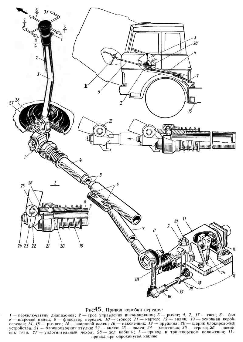
Telescopic type, consists of a mechanism located directly on the gearbox 13, and a system of rods and levers associated with the lever 3, mounted in the cab.
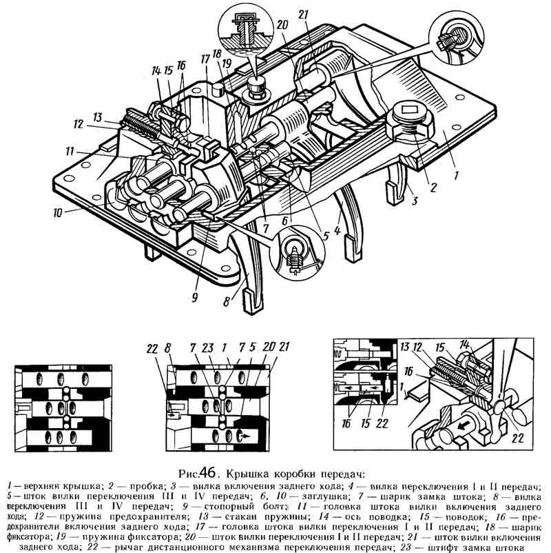
In the tides of the upper cover 1 (Fig. 46) of the main box, three rods are mounted: on the extreme right (in the direction of the car) the fork 3 of the reverse gear is fixed, on the middle - the fork 4 for switching the first and second gears of the main box, and on the third - the fork 8 shifting the third in the fourth gear of the main box.
The rods 5, 20 and 21 move in the guide supports of the upper cover using the lever 22. There are heads (11 and 17, respectively) on the reverse rod and the shift rod of the first and second gears of the main box. The lever 22 enters the head 17 directly, and into the head 11 through the leash 15 for switching the reverse gear.
To engage the third and fourth gears of the main gearbox, the lever 22 can enter directly into the groove of the shift fork 8 of these gears. The position of the reverse rod is fixed in the cover by means of a fuse 16, which is included in the leash 15 under the action of a spring 12 placed in a special glass 13. Only by overcoming the spring force of this fuse, it is possible to turn on reverse... The rods are held in gear and in neutral by ball clamps. To prevent the possibility of simultaneous engagement of two gears, a special ball-type lock is installed in the rods.
On the top cover of the main box, the crankcase 11 (see Figure 45) of the remote control mechanism of the main box is mounted, in which the gear shift shaft 12 is located with the lever 14 fixed on it and the intermediate lever 18 connected to the longitudinal rod 7 of the remote drive.
In the housing of the remote mechanism is a ball lock 9 of the gear selection. The longitudinal rod 7 can perform both longitudinal and angular movements. The angular movement of the rod causes an axial movement of the shaft 12, which leads to the connection of the lever 14 sitting on it with a certain slider in the upper cover of the main box 13. The movement of the longitudinal thrust causes the rotation of the shift shaft 12 and the lever 14 sitting on it. moves together with the fork until the corresponding gear is engaged.
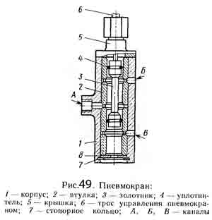
The additional box is controlled by a pneumatic crane with the range switch 1 (see figure 45), located on the handle of the gear shift lever 3.
Additional box switching mechanism (fig. 47).


Consists of a pressure reducing valve 12, an air distributor 6, a pneumatic valve 5, intake valve 8, working cylinder 1 and air ducts.
Reducing valve 3 (Fig. 48) serves to reduce the pressure of compressed air supplied from the pneumatic system of the vehicle to 4.75 kgf / cm² - the operating pressure of the pneumatic system of the gearbox. Air diffuser 23 directs compressed air from the inlet valve 17 into one or the other cavity of the working cylinder 25 and bleeds air from its cavities.
Pneumatic valve 5 controls the air distributor. When the 6-range switch is lowered, the air distributor spool is set to the position corresponding to the direct drive in the additional box. With the switch up, go to the downshift position.
The inlet valve 17 provides the supply of compressed air through the air distributor 23 to the working cylinder 25 only when the transmission is turned off in the main box. When the gear is engaged in the main box, the inlet of the valve is closed by the pusher 16 and air does not enter the air distributor and the working cylinder, the unloading opening in the valve body is open, both cavities of the working cylinder are connected to the atmosphere.
With the range switch 1 raised (see Figure 45), cable 6 moves the spool 3 (Figure 49) to the position at which the compressed air supplied from the pressure reducing valve to channel A through the pneumatic valve channel enters channel B and then to the air distributor on the inclusion of a downshift. Channel B at this time through the filter 8 is connected to the atmosphere.
When the range switch is lowered, the cable moves the spool 3 to the position at which the compressed air through channel A enters channel B and from there to the air distributor for direct transmission. At this time, channel B is connected to the atmosphere through cover 5.
The gear shift mechanism of the additional box is located in the upper cover of its crankcase. Here is the rod 13 (see figure 44), connected to the piston of the pneumatic cylinder 14. The direction of movement of the rod with the fork 10 of the gear shift of the additional box attached to it depends on the pressure supplied to the pneumatic cylinder to the left or right of the piston, which causes the large 20 or small 21 synchronizers, that is, a reduction or direct transmission of an additional box.
On the top cover of the additional box there is a sensor for the synchronizer, the inclusion of a downshift. When the rod 13 and the shift fork 10 of the additional box are moved from one position to another, a control lamp connected to the switch terminal 35 lights up in the driver's cab. The lamp goes out as soon as the selected (direct or downshift) gear is fully engaged.
In addition, there is a locking device on the top cover of the auxiliary box for disabling the auxiliary box when towing the vehicle. To do this, having set the fork 10 to a neutral position, the locking bolt 9 is screwed all the way into the hole made on the rod, and counter it in this position with a nut.
Gearbox lubrication system.
It is combined: the bearings of the gears of the secondary shafts of the main and additional boxes are lubricated under pressure, the teeth of the gears and the bearings of the shafts are lubricated by spraying. Oil is sucked from the oil bath of the crankcase through the intake 29 and the gear channel system oil pump... The pump is driven from the end of the intermediate shaft of the main box. The pump has pressure reducing valve, which is adjusted to a pressure of 0.78kgf / cm² and when the oil pressure is too high, it connects the discharge channel of the pump to the suction channel. The oil baths of both crankcases are connected to each other by a channel to ensure the same oil level in them. The inner cavity of the gearbox housings is vented to the atmosphere by means of a breather.
The gearbox has an oil filler hole on the main box cover, an oil level check hole on the side wall of the main box and two drain holes from the bottom of the crankcases of the main and additional boxes.
The gearbox drive of Maz-5516, Maz-5440, 64229, Maz-54323, 54329 and YaMZ-239 vehicles is shown in Figure 4.
During operation, if necessary, the following adjustments of the gearbox drive are made:
The procedure for adjusting the control of the YaMZ-239 gearbox for Maz-5516, Maz-5440, 64229, Maz-54323, 54329 cars is as follows:
Set lever 2 to neutral position;
By longitudinal movement of the plate 16 with the bolts 17 released, set the angle a of the lever 1;
By changing the length of the rod 3, set the angle.
In case of insufficient travel of the plate 16 or the range of adjustment of the thrust 3, loosen the bolts 5, move or rotate the thrust 6 relative to the shank 4, tighten the bolts 5 and repeat the adjustment of the angles a, b as described above.
Angle a should be 80 °, angle b 90 °.
Adjustment of the locking device of the telescopic elements of the YaMZ-239 gearbox of Maz-5516, Maz-5440, 64229, Maz-54323, 54329 vehicles with a raised cabin as follows:
Undo the pin 8 and disconnect the rod 6 from the fork 9 of the gearbox drive lever;
Push the inner rod 6 up to the stop of the projections of the earring 12 into the grooves of the tip 15;
Keeping the mechanism compressed, screw in the shank until the mechanism is locked by the sleeve K) under the influence of the spring 11:
Tighten the lock nut 13, check the accuracy of the locking mechanism. When the mechanism is locked, the axial and angular backlash should be minimal.
In the unlocked position, the sleeve 10 is shifted to the left. The movement of the extension should be smooth, without jamming, and the locking mechanism should ensure that the extension rod is firmly locked in its original position.
When connecting rod 6 to fork 9, the hole in the shackle for pin 8 must be located above the longitudinal axis of rod 6. Adjust the drive with the engine off.
When the cab is lifted, oil under pressure from the cab lifting pump is supplied through the hose 7 to the cylinder of the locking device and the mechanism 6 is unlocked.
After lowering the cab, to securely fix the telescopic mechanism 6 in the locked position, it is necessary to move the gear shift lever 1 forward in the direction of the vehicle in a movement similar to engaging a gear. In this case, the mechanism is blocked and is subsequently ready for operation.
Scheme of gear shifting of the check point of cars Maz-5516, Maz-5440, 64229, Maz-54323, 54329 and YaMZ-239, see Figure 5.
Fig. 4. YMZ gearbox control drive for cars Maz-5516, 64229, Maz-54323, 54329
1 - lever; 2 - lever; 3.4 - thrust; 5.17 - bolt; 6 - thrust (telescopic mechanism); 7 - hose; 8 - finger; 9 - plug; 10 - bushing; 11 - spring; 12 - earring; 13 - lock nut; 14 - shank; 15 - tip; 16 - plate; 18 - switch
Gearbox control drive for cars Maz-5516, Maz-5440, 64229, Maz-54323, 54329 with MAN engine.
When controlling the gearbox of cars Maz-5516, Maz-5440, 64229, Maz-54323, 54329, be guided by the following:
The control of the main gearbox and the demultiplier is carried out using the gearbox lever according to the diagram shown in Figure 19 (gearbox ZF).
The transition from the slow range to the fast range is carried out by moving the lever in the neutral position away from you, overcoming the force of the retainer, from the fast range to the slow range - in the reverse order.
The divider is controlled by a flag on the gear lever handle. The transition from the slow range (L) to the fast (S) and vice versa is carried out by pressing the clutch pedal all the way after the flag is moved to the appropriate position. Switching is possible without disabling the transmission in the main gearbox.
Adjustment of the gearbox control drive of the gearbox of cars Maz-5516, Maz-5440, 64229, Maz-54323, 54329
During operation, if necessary, the following adjustments of the gearbox drive of Maz-5516, Maz-5440, 64229, Maz-54323, 54329 cars are made for MAN engines:
Adjusting the position of the lever in the longitudinal direction;
Adjusting the position of the lever in the transverse direction;
Adjustment of the locking device of the telescopic drive elements.
Adjustment of the position of the lever 1 (Figure 7) in the longitudinal and transverse directions is carried out by moving and rotating the rod 5 in the shank 6 with the bolts 7 released.
In this case, the angle a should be 85 °, the angle e = 90 °. The angle a can also be adjusted by moving the plate 3 with the bolts 2 released.
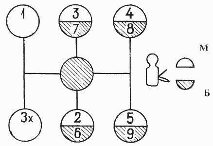
Fig. 5. Scheme of gear shifting of the check point of cars Maz-5516, Maz-5440, 64229, Maz-54323, 54329, YaMZ-239
M - slow range; B - fast range.

Fig. 6. Scheme of gear shifting of the gearbox ZF of cars Maz-5516, Maz-5440, 64229, Maz-54323, 54329
L - slow range; S - fast range.

Fig. 7. Gearbox control drive for cars Maz-5516, Maz-64229, Maz-54323, 54329
1 - lever; 2, 7 - bolt; 3 - plate; 4 - hose; 5 - intermediate mechanism; 6 - shank; 8 - growl
The gearbox drive of Maz-5440 vehicles is shown in Figure 8.
Switching of the main box is made by lever 1 of the remote control mechanism. The additional box is controlled by the range switch 18 located on the gear shift lever 1.
The lower position of the range switch turns on the fast range in the additional box, with the upper position the slow range.
During operation, if necessary, the following adjustments are made to the gearbox of Maz-5440 vehicles:
Adjustment of the angle of inclination of the lever 1 in the longitudinal direction;
Adjustment of the angle of inclination of the lever 1 in the transverse direction;
Adjusting the telescopic locking device. To adjust the angle of inclination of the lever in the longitudinal direction:
Set the lever 2 to the neutral position by tightening the neutral position lock on the shift mechanism 20 (for the YaMZ gearbox - 238M).
Check the neutral position of the gearbox of the gearbox of Maz-5440 cars by moving the roller of the lever 2 in the axial direction by pressing it by hand. In this case, the roller should move by an amount of 30 - 35 mm;
Loosen the tightening of the bolts 17 and by longitudinal movement of the plate 16 set the angle "a" to 90 degrees;
If the travel of the plate 16 is insufficient, loosen the bolts 5, move the rod 6 relative to the shank 4, tighten the bolts 5 and repeat the adjustment of the angle "a" by moving the plate 16.
Adjustment of the lever 1 in the transverse direction is carried out by changing the length of the lateral rod 3 by disconnecting one of the tips with unscrewing the nut of its fastening, followed by adjusting the length so that the lever 1 takes a vertical position.
After adjustment, return the neutral position lock to its original position (for the YaMZ-238M gearbox).
Adjustment of the locking device of the telescopic gearbox of the Maz-5440 vehicles should be done as follows:
Unpin the pin, unscrew the nut, remove the pin and disconnect the rod 6 from the fork 9 of the gear lever;
Loosen the lock nut 13 and unscrew the shank 14 up to the thread stop;
Push the inner rod 6 up to the stop of the earring projections into the grooves of the tip 15;
Keeping the mechanism compressed, screw in the shank 14 until the mechanism is locked by the sleeve 10 under the influence of the spring 11;
Tighten the lock nut 13, check the accuracy of the locking mechanism. When the mechanism is locked, the axial and angular backlash should be minimal. In the unlocked position (bushing 10 is shifted to the right), the internal link should be pushed out by the return spring by 35 - 50 mm.
Further movement of the extension should be smooth, without jamming and the locking mechanism should ensure that the extension rod is clearly fixed in its original position.
Avoid bending and bending of the drive rod and its telescopic components. Adjust the gearbox drive with the engine off.

Fig. 8. Gearbox control drive for cars Maz-5440
1,2 - lever; 3, 4, 6 - thrust; 5, 7, 17 - bolt; 8 - finger; 10 - bushing; 11 - spring; 12 - earring; 13 - nut; 14 - shank; 15 - tip; 16 - plate; 18 - switch 19 - ball; 20 - switching mechanisms.
_______________________________________________________________________________________
_______________________________________________________________________________________
_______________________________________________________________________________________