The use of sand in construction is quite wide, since this type of material is most suitable for creating building structures, finishing materials, such as plaster. The material is widely used in the process of making masonry mortars. The average density of sand can decrease due to the content of clay impurities, deteriorating the quality indicators of this bulk material.
The average density of sand can decrease due to the content of clay impurities, thereby deteriorating its quality indicators.
It is necessary to use construction sand as a production raw material, knowing not only the size of its particles, but also the properties of the various impurities it contains. These can be clay minerals, salt, humus, mica, the presence of which limits the area of using construction sand.
Characteristics of construction sand
Sand grains (its fragments) in size can vary in the range of 0.1-1.0 mm. The grain size allows you to divide the building material into the following types:
- Dusty.
- Coarse-grained.
- Clayey.
Among the main characteristics building material the following are distinguished:
- radioactivity class;
- size indicator;
- bulk density indicator;
- impurity content indicator;
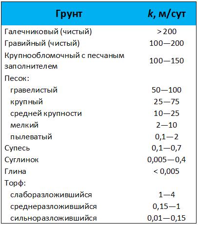
- filtration coefficient.
There are a large number of types of material, since each of them has different content impurities in its composition, which are clay and dust particles. Its use in construction is associated with compulsory screening or washing. Important role application of one type or another plays a role in the size.
It should be remembered that river sand is the cleanest, unlike sea sand, which is polluted with salts. Fresh water is used to wash the sea sand. The strength of the prepared masonry mortar from sand decreases in the presence of clay impurities in it.
Construction sand, which is made in accordance with the requirements stipulated by the standard GOST 8736 - 93, is used for:
- Masonry, screed and plaster.
- Manufacturing of cement.
- Concrete making.
- Road pavement arrangement.
- Glass making.
This building material is widely used in conditions Agriculture, and independent construction, while it is measured in buckets, and not in cubic meters or tons. The volume of a bucket of 10 liters is equal to 0.01 m³, it sometimes includes up to 14 kilograms of dry material.
Depending on the specific mining method, the building material is used in various industrial fields. For example, in the chemical industry, the main emphasis is placed on the use of quartz building sand. Quarry is used to cover cleared roads using snow harvesters. It is impossible to do without the use of sand in any construction project.
Density of building sand and its definition
Material according to its origin is divided into artificial and natural, the latter include grains, the size of which is 0.16-5 mm, and the bulk density is in the range of 1300-1500 kg / m³. Depending on the mining method, the sand can be river, sea and quarry. The use of artificial ones is rare, but they are divided into heavy and light ones.
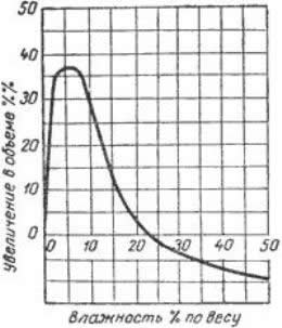
Any kind of sand has distinctive feature associated with free absorption of moisture, which helps to remove it from the finished product, increasing its free-flowing properties. With a change in its volume, the bulk density also changes, which depends on the change in moisture, the level of the latter can be in the range of 0-20%.

If the moisture content is in the range of 3-10%, then such material differs sharply in its density from dry. A grain of sand covered with a layer of water significantly increases the volume of the material. As the moisture content of the material increases, the bulk density of the sand increases due to the displacement of air during the filling of intergranular voids with water.
If it is necessary to dose the material by its volume, then the bulk density of the sand is taken into account as its change with the growth of moisture. The quality level of a material is determined by the degree of its density. It is this indicator that determines the sand content in 1 m³ of volume. The moisture and porosity of the material determines the density level, depending on these parameters.
The indicator is very important in the field of professional construction, since it affects the degree of strength of the facilities being built and their service life. If the bulk material has an unconsolidated state, then its properties are determined by the bulk density.

Natural building material has a density of 1.3-1.8 t / m³, which is the higher, the higher the content of clay in the sand. This parameter is necessary when determining the quality that the grain composition possesses. Mineral composition can be determined by the geographic location of the mines. At the same time, this material is the most pure, since it sometimes does not contain impurities.
The density index of the quarry type is 1.4 t / m³, since it contains clay impurities. For this reason, sand is not used for the preparation of concrete solutions. High Quality... They use quarry sand in order to reduce the cost of concrete mortar.
The procedure for calculating and determining the amount of sand through its density
The formula for calculating the mass has the following form: m = V * p, in it the letter V denotes the volume, and the letter p denotes the density. For example, if you want to know required amount sand, if its volume is 10 m³, substituting the values in the formula, you can get:
m = 10 * 1.3 = 13 t.
When calculating the result, an average density of 1.3 t / m³ is used. It should be borne in mind that insufficient level strength is associated with the presence of increased voidness. In this case, the solution is prepared by increasing the amount of substances that are astringent.
Calculation of the amount of sand through its density: m - mass, V - volume.
This may not be beneficial in construction, since with an increase in the volume of binders, costs increase simultaneously with the cost of concrete mortar. Since the payback is important indicator for any construction company, it will be unprofitable to build objects using such a solution. If the construction is private, then its size will not affect the cost of expenses.
High humidity can lead to a decrease in the average density, and the reason for this is the adhesion of fractions. Decrease this indicator will continue until the humidity reaches 10%. In the course of further growth, there is an increase in the volume of liquid filling the space, which is free, therefore the indicator increases. With a constant change in the parameters, the quality of the concrete solution can change. Compliance with delivery standards is of great importance.
Available methods for determining the average density of sand
The average density of bulk material, for example, building sand, is also called bulk. The total volume includes pores directly in the material and those voids that are between the grains. Most bulk materials have an average density that is less than true.
To determine the indicator, using improvised means, they take a bucket to fill it with sand from a height that is equal to 10 meters. The bucket must be ten liters. The material should be poured until a hill is formed, which must be cut strictly horizontally, which allows you to get a flat surface with a full bucket.
The resulting amount of sand should be weighed, only then the calculation of the indicator should be started. For this purpose, the mass is divided by the volume, kilograms converted to tons should be divided by 0.01 m³. To obtain more accurate calculations, the measurement should be carried out twice, only after that the results should be summed up and divided by 2.
To determine, you can use other calculation methods, since this indicator is a characteristic that allows earthwork to be carried out.
Other ways to calculate density
Determination of the indicator involves the use of the shurfik method, which allows you to determine the density of loose types of soil. Subsequent drafting earthworks must contain the value of the average density indicator. For this purpose, a small depression is made in the ground in the form of a pit, which is called a shurfik. In this case, the sand is displaced, which should be placed in a special container for further weighing. Above the pit itself or the pit itself, a tin cone must be placed.

Then they proceed to the stage of determining the indicator for the main material, which is covered with dry sand. Having previously determined the total volume of the pit, you should calculate the volume of material, which is weighted. This method definition is simple, as it only gives the relative calculation that can be assumed.
A more accurate method is the radiometric method based on the use of radioactive radiation. The scattering and radiating properties of the material should be evaluated by this parameter. Among the additional quantities characterizing career type material, the following main parameters can be distinguished:
- The degree of radioactivity is class 1.
- Bulk density indicator - 1.4 t / m³.
- The density of the grains is 2.6 g / cm³.
- The specific gravity of the clay content in% is 1.9.
The main indicators of the average additional characteristics inherent in river sand is:
- Class A radioactivity level (47 BK / kg).
- Bulk density value equal to 1.4 ± 0.1 t / m³.
- The content of a certain number of impurities in% is 0.1.
The bulk density of bulk building materials, such as sand, is its density if it is in an unconsolidated state.
For self-determination of medium density, a measuring vessel with a volume of 1 liter is taken, the sample is poured into it and weighed. If too high level humidity, the sample should be placed in a vessel with a volume of 10 liters. After that, it is required to convert all parameter values to the required value.
Sand with a high clay content cannot be used for the manufacture of plasters, high-quality concrete, various building solutions, since otherwise the strength and frost resistance of the material will decrease.
The average density is less important than the usual density of the material, since the calculation of this indicator is associated not only with the inclusion of the volume of particles, but also the space between them. If the bulk material is compacted, then its density is no longer bulk. So, the sand poured into the back of a truck has a bulk density, that is, an average one.
At the signal of the car inspector, release the automatic brakes: in trains with up to 350 axles, the driver moves the crane handle to the train position; in trains with a length of more than 350 axles, the operator's crane handle is set to the first position and the pressure in the equalizing tank is increased by 0.5 - 0.6 kgf / cm2 more charger is then transferred to the train position. Car inspectors should check the release of the brakes for each car in the train for the brake cylinder rod leaving and the departure of the shoes from the wheels. If wagons with a brake that have not been released are identified, it is not allowed to release them manually until the reasons for the non-release are clarified. Identified faulty air distributors must be replaced with serviceable ones. After that, the action of the brakes on cars with replaced air distributors is again checked.
 Minimum pressure in the tail car line freight train.
At the end of testing, the driver is handed a certificate of the form VU-45 about providing the train with brakes.
Full testing of automatic brakes before long descents with a steepness of 0.018 and more is carried out with holding in the braked state for 10 minutes. During this time, no air distributor should release spontaneously.
Order of conduct full testing automatic brakes in a freight train by one inspector. After attaching the locomotive to the train and charging brake line the car inspector together with the driver check the tightness of the brake line of the train. Then, at the command of the car inspector, the driver performs the braking stage set for complete testing of the brakes, and the inspector walks along the train from head to tail to check the operation of the automatic brakes. The driver at this time is obliged to check the tightness of the brake line when IV position of the operator's crane handle.
Having reached the tail of the train, the car inspector gives the signal to release the brakes. After releasing the brakes and recharging brake network train inspector measures the pressure in the brake line of the tail car. Observing precautions, the inspector opens the end valve of the tail car for 8 - 10 seconds in a freight or cargo-passenger train, and in a passenger train until the accelerators are triggered emergency braking air distributors.
The wagon inspector must measure and record in the certificate of the form VU-45 the exit of the brake cylinder rod, the number of the tail car and the charging pressure in the brake line of the last car (in freight trains).
When the brakes of the locomotive are triggered, which is determined by the lighting of the lamp "TM" brake line break alarm with sensor No. 418 , a drop in pressure in the brake line or a specific noise of the driver's crane supplying the brake line leak, the driver must stretch the speed meter tape, after which, after at least 2 minutes. (in freight and freight-passenger trains) perform the braking stage by reducing the pressure in the surge tank by 0.5 - 0.6 kgf / cm2 and after the end of the air release from the brake line through the driver's crane, release and charge the train's brake network.
On a train with a length of more than 100 axles, a car inspector must measure the maximum brake release time for the last two cars in the train. In the absence of radio communication, the car inspector measures the time from the moment the tail car end valve is opened to the start of the stock leaving brake cylinders and away brake pads from the rolling surface of the wheels. The locomotive driver measures the time from the moment the locomotive's automatic brakes are triggered, determined by the lighting of the lamp "TM" signaling device No. 418 , until the moment of setting the operator's crane handle to the first position. The driver informs the car inspector of this time, who subtracts it from the time measured at the tail of the train, and enters the result into the form. VU-45(this procedure for measuring the brake release time tail carriages in the absence of radio communication installed on the October road). In a train with up to 100 axles (inclusive), after releasing the brakes of the last car, the car inspector does not measure the release time of the tail cars, but immediately goes to the head of the train, identifying unreleased brakes.
After the end of the complete testing of the brakes, the inspector of the cars gives the locomotive driver a certificate of the brakes of the form VU-45.
Complete testing of the brakes on the electric train performs locomotive crew, and when leaving planned types of repair (except TO-2) together with the foreman or foreman of the automatic depot department.
Full brake testing is carried out:
After renovation or Maintenance;
After standing without a crew at a station or depot for more than 12 hours;
After attaching the carriages to the train.
After each complete brake test in the log technical condition shape TU-152 an entry is made indicating:
MVS numbers and series;
Dates and times of full brake test;
Pressure limits in main tanks maintained by a pressure regulator;
The pressure in the brake line in the train position of the operator's crane handle;
The amount of air leakage from the brake network of the train;
Surname and signature of the driver and driver's assistant, and after repair or maintenance (except TO-1), the foreman and driver.
A full brake test begins with checking that the valve handles on the supply and brake lines are in the correct position. Then check the operation of the pressure regulator. The pressure in the main tanks must be kept within 8.0 - 6.5 kgf / cm2 with a deviation of no more 0.2 kgf / cm2.
After charging the brake and supply lines, check their tightness. To do this, on an electric train with a crane driver service No. 395 shut off the isolation valves on the brake and supply lines, and with the valve service number 334E shut off the isolation valve on the supply line. The decrease in pressure observed on the pressure gauge should be:
In the brake line from normal charging pressure by no more than 0.2 kgf / cm2 within one minute;
In the power supply network with 7,0 before 6.8 kgf / cm2 in 3 minutes or s 7,0 before 6.5 kgf / cm2 in 7.5 minutes.
Before the checks, the electric train must be secured against leaving.
At the next stage, the density of the surge tank of the driver's crane is checked.
Check the work from the beginning EPT... After charging the brake line, turn off the control generator (phase splitter) and turn on the searchlight, signals and other consumers of electricity. When the brake switch handle is pressed down in the working and non-working control cabins and in the whole negative wire, it should light up control lamp "TO"... The voltage in the circuit according to the voltmeter should be within 45 - 50 V.
Then move the operator's crane handle service number 334E v IV position, no. 395E into position VА... Should light up signal lamp braking "T" and at tap No. 334E shut off the valve, and with valve no. 395 - turns off briefly "SK" on the EPK service No. 150I without hitchhiking. In this case, the release is allowed compressed air from the brake line through the valve No. 395 and the decrease in pressure in it by no more than 0.5 kgf / cm2.
When the brake cylinder is filled to the full pressure, the operator's valve handle should be moved to the overlap position without supplying the brake line leaks. The driver's assistant walks along the train and checks the actuation of the brakes on each car by the exit of the brake cylinder rod and pressing the pads against the wheels.
On a signal from the assistant, the driver turns off the brake switch on trains up to no. 1028 , and on other trains EPT turn off the power switch. The driver's assistant controls the release of the brakes by the release indicator lamp and the departure of the brake pads from the wheels of each car.
At the second stage, the operation of the automatic brake is checked. Turn off before checking EPT... From the set charging pressure, the sensitivity of the automatic brakes to braking is checked. To do this, it is necessary to perform the first stage of braking with a decrease in pressure in the surge tank by 0.5 - 0.6 kgf / cm2... After reducing the pressure in the surge tank by the required value, the valve handle No. 334E translate into III position, and tap No. 395E- v IV position. After 5 min. the driver's assistant checks the actuation of the brakes on each carriage by the exit of the brake cylinder rod and the pressing of the pads to the wheels.
At the command of the assistant driver "Release the brakes" the driver moves the crane handle No. 334E into position IIA, and tap no. 395 - in position II... After releasing the brake of the last car, the driver's assistant checks the departure of the shoes from the wheels and the departure of the brake cylinder rod for each car in the train.
From the opposite control cab, the locomotive crew should check the operation of the automatic and electro-pneumatic brakes as in the abbreviated brake test.
- How to determine the density of a building material?
- What additives and ratios of the main components affect the density and porosity of concrete?
- How to get concrete with optimal medium density?
- As a placeholder concrete mix affects the density of the material?
- Indicator of the average density of concrete and performance properties material
Concrete has a number of characteristics, the most difficult of which is density. If various components are added to the mixture of concrete solution, then this property will increase or decrease. When the material hardens, its strength increases.
The strength of concrete directly depends on its density.
Since construction is associated with the use of a large number of types of different concrete, there is special classification of this material. Distinguish between lightweight, extra lightweight and heavyweight concrete. For example, the average density of heavy concrete is 2.45 g / cm³, and light concrete is 1.40 g / cm³.
How to determine the density of a building material?

Average is important characteristic, defined as the ratio of its mass to volume. Per unit of measurement this parameter take g / cm³, kg / m³ or percent. If we take this value into account in percentage terms, then it will be less than 100%. Its influence on the quality of the product is directly proportional, that is, with a high studied indicator of the material, its strength increases.
To calculate the average density of a building material in the form of a piece with pores (but not voids), you can use the formula (1): pc = m / Ve, where:
- m is the designation of the mass of the material (g, kg);
- Ve is the volume of building material (in a piece), which is measured in cm³ or m³.
The determined indicator is necessary to study the porosity of the product and its thermal conductivity.
Back to the table of contents
What additives and ratios of the main components affect the density and porosity of concrete?
Simultaneously with the process of evaporation of unnecessary water, an increase in density occurs. To do this, you can specifically use pozzolanic Portland cement, which is an expanding alumina cement. After its solidification, no voids are formed, therefore the level of the studied indicator increases.
With a decrease in the volume of water used and an increase in the amount of cement, an increase in the indicator occurs. As a result of using the resulting concrete, the laying process becomes more complicated.
The presence of plasticizing additives that improve the solution has a great influence on the structure of the product. It is required to distinguish between the characteristics of the solution and the finished product by calculating the average density indicator. It is not difficult to calculate if you know the ratio of the components used, for example, fillers and cement.
When the setting of concrete is completed, the process of curing and evaporation of excess water follows. The finished product has less weight than the mixture. This discrepancy is due to the amount of water and cement used. Due to an increase in water and a decrease in the proportion of cement in the mixture, the finished composition comes out more liquid.
Back to the table of contents
How to get concrete with an optimal average density?
You can get the maximum value of the average density of concrete if you carefully select the grain component, which allows you to make the voids smaller. When creating any building structures that are made by a monolithic method, the formation of voids in their structure cannot be avoided.
In order to improve the quality of laying the material during construction, the water / cement ratio must be reduced. Since when the water in the concrete solution decreases, the ratio of the mass of the substance to the volume of the substance increases, then carrying out construction works will be time consuming. At the same time, it is necessary to use special equipment, which is a vibration compactor.
Due to the use of additives-plasticizers, the plasticity of the concrete mixture increases, as well as the characteristics of the finished concrete. Initially, due to additives, the mixture is compacted, and excess water is removed. This can be achieved by evacuating concrete. In this way, high-quality laying of floor coverings of industrial facilities or open areas as well as roads.
The use of the method is characteristic exclusively for solutions with silicate-cement or slag-silicate-cement additives. The rest of the cases are related to carrying out similar work based on the results obtained during the preliminary test.
It is possible to determine the density of concrete, taking into account all the indicators characteristic of the mixed components. Most effectively in practice, materials are used that are created according to state standards when the investigated characteristic is known in advance.
Back to the table of contents
How does concrete aggregate affect material density?
Typically, the average density of concrete is influenced by parameters such as:
- bulk density;
- grain filler;
- costs of binders and water.
Any building mixture contains sand and filler. Almost always, the change in the bulk density of the used sand occurs in a small range. With greater intensity, there is a change in the mass ratio of this material to the other constituent parts of the solution. Therefore, the influence of the aggregate on the average density is greatest.
For a more detailed consideration of this issue, it should be borne in mind that the dependence of the density of concrete on the aggregate is determined by the excess of its share over the volume of all other components of the mixture. Most types of products are characterized by greatest value indicator of its own volumetric mass.
The presence of lightweight aggregates in the structure of the building material under study assumes the minimum density of the material. Due to this, the bulk density of the product is reduced. The use of aggregates with the highest density occurs more often, since the structure requires a certain required strength.
This classification is based on the dependence on the mass of the aggregate, which is used in the process of making concrete. If the filler is granite, limestone, dolomite, then with a material strength of 60 MPa or 600 kgf / cm² the average density is from 2200 to 2400 kg / m³. This kind products are heavy concrete.
Measurement of the vacation time should be carried out with full or reduced testing of the brakes from the locomotive, if at the PHO or the station, complete testing of the brakes was carried out from a stationary compressor unit, during the operation of checking the integrity of the brake line of the train.
The start time of measuring the brake release time for the last two cars is determined:
In the presence of radio communication between the head and tail of the train, the Driver, at the command of the car inspector to check the integrity of the brake line, controls the integrity check by the pressure drop in the TM and the ignition of the signal lamp of the integrity control sensor
the brake line produces a braking stage of 0.5-0 6 kgf.cm and pulls the tape.
At the command of the head inspector and the driver set the operator's crane handle to the train position, the tail inspector measures the vacation time. The end of the timing is determined by the departure of the brake pads from the rolling surface of the wheelsets and the complete departure of the brake cylinder rods.
In the absence of radio communication with the driver: An inspector or a worker involved in a reduced or complete testing of the brakes measures the time from closing the tail car's end valve after the train's brake line has been purged. The end of the timing is determined by the departure of the brake cylinder rods and the departure of the brake pads from the rolling surface of the wheelsets. The operator's crane handle is in the train position.
The time for the complete release of tail cars when installing the operator's crane control body, the train position should be no more than 80 seconds.
Repair manual braking equipment"No. 732 TsV-TsL from 2011. permits release from planned types of car repairs with brake release up to 70 sec. The braking devices of cars with a delayed release of more than 70 seconds in trains with up to 400 axles and 80 seconds in trains with more than 400 axles must be replaced.
When measuring the time of release of the brakes with the setting of the control body of the driver's crane in the charging position - release with overstating the pressure in the brake 0.3-0.5 kgf / cm 2 and subsequent setting in the train position. Vacation time should be no more than:
50 sec to ZOOS.
60 sec up to 300 - 400axis
80 sec over 400 axes
This method of measuring the release time of tail car brakes
apply for a control sample of brakes.
8.3. With full testing of automatic brakes for cargo and passenger
trains perform:
8.3.1 . Installation of a measuring device for measuring the pressure in the brake line of the tail car. BHV installation in trains weighing 8300-9000t. (when installing BHV, the measuring device is not used).
8.3.2 . Charging the brake line and measuring the charging pressure in the brake line of the tail car. Measure the pressure in the brake line of the tail car of the train after fully charging the brake line of the entire train. The pressure readings in the brake line of the tail car with the train position of the driver's crane control body should not differ more than:
a) by 0.03 MPa (0.3 kgf / cm 2) from the charging pressure in the driver's cab (in the head) with a train length of up to 300 axles;
b) by 0.05 MPa (0.5 kgf / cm 2) with a train length of more than 300 to 400 axles inclusive;
c) by 0.07 MPa (0.7 kgf / cm 2) with a train length of more than 400 axles;
Dismantling of the measuring device for measuring the pressure in the brake line of the tail car;
8.3.3 . Checking the free passage of compressed air to the tail car and the integrity of the brake line of the train.
The check is carried out at the command of the car inspector after the train's brake network is fully charged by opening the last end valve of the tail car for 8-10 seconds. On trains weighing more than 8300t. with BHV additionally after connecting the BHV unit when checking the operation of the BHV from the driver's cab.
The driver registers the integrity check on the device (KPD-3 P, on the 3CJI-2M speed meter tape) and on the light of the integrity control sensor.
In the presence of radio communication between the head and tail of the train, the driver performs a braking stage 0.5-0.6 kgf / cm 2
At the command of the car inspector, the driver releases the brakes with the setting of the driver's crane control body in the train (2nd) position. Tail surveyor
wagons or an employee involved in testing the brakes measures the vacation time. The end of the timing is determined by the departure of the brake pads from the rolling surface of the wheelsets and the complete departure of the brake cylinder rods.
In the absence of radio communication with the driver: An inspector or a worker involved in testing the brakes measures the time from closing the end valve of the tail car after purging the brake line of the train. The end of the timing is determined by the departure of the brake cylinder rods and the departure of the brake pads from the rolling surface of the wheelsets. The operator's crane handle is in the train position.
The time for the complete release of the tail carriages when the driver's crane control body is installed in the train position should be no more than 80 seconds.
8.3.4 . The driver, together with the head inspector of the cars, measures the density of the brake line with the train position of the driver's crane handle.
With the train position of the driver's crane control body, the check is carried out after the compressors are turned off upon reaching the maximum pressure in the main tanks of the locomotive and the subsequent decrease in this pressure by 0.04-0.05 MPa (0.4-0.5 kgf / cm 2) with time measurement further decrease in pressure by 0.05 MPa (0.5 kgf / cm 2). table
The shortest allowable time for pressure reduction when checking the tightness of the brake line, depending on the length of the train and the volume of the main tanks of the locomotives.
|
The total volume of the main locomotive tanks, l |
Time in seconds, with the length of the train in the axles |
||||||||
Notes:
When checking the density of the brake line of a freight train at a charging pressure of 0.52-0.54 MPa (5.3-5.5 kgf / cm 2), reduce the time rate indicated in the table by 10%.
When operating in a multi-unit system, when the main tanks of the locomotives are connected to a common volume, specified time increase in proportion to the change in the volume of the main reservoirs.
If the total volume of the main tanks of the locomotive differs from that presented in the table, the volume should be taken according to the nearest smallest volume given in the table.
Each locomotive must have an extract in a conspicuous place indicating the total volume of the main tanks.
8.3.5 . When the density of the brake line reaches the established norm, the effect of the automatic brakes of the train carriages on braking is checked. The check is carried out after the pressure in the brake line of the train is reduced by 0.06-0.07 MPa (0.6-0.7 kgf / cm 2) from the charging pressure, followed by the transfer of the driver's crane control body to a position that maintains the specified pressure in the brake highways after braking, after 120 seconds (2 minutes) for freight trains, for which all air distributors are switched on to a flat mode, car inspectors are obliged to check the condition and operation of the brakes throughout the train for each car and make sure that they are working properly for braking at the exit of the rod brake cylinders and pressing the pads against the rolling surface of the wheels.
Checking the density of the brake line of the train in the position of the control body of the driver's crane, which maintains the specified pressure in the brake line after braking, is performed by measuring the density of the brake line of the train, which should not differ from the density at the train position of the control body of the driver's crane by more than 10% downward ...
On freight locomotives equipped with a brake line density control device, check the density according to the indication of this device.
8.3.6 ... Checking the operation of the automatic brakes of the train carriages on vacation.
After the end of checking the action of brakes on braking and the subsequent release of the train brakes by installing the control body of the driver's crane in the train position, the car inspectors are obliged to check the release of the brakes throughout the train for each car and make sure that they are working normally for the release of the brake cylinder rod and the departure of the pads from the rolling surface of the wheels.
In freight trains of increased length (more than 350 axles in length), the release of automatic brakes is carried out by setting the control body of the driver's crane to the release position until the pressure in the equalizing tank is obtained by 0.05-0.07 MPa (0.5-0.7 kgf / cm 2) higher charging pressure.
Inspectors of carriages are obliged to check the release of brakes throughout the train for each car and to make sure that they are working normally on leave for the departure of the brake cylinder rod and the departure of the pads from the rolling surface of the wheels.
If it is found that the air distributors did not work on vacation, it is not allowed to manually release them until the reasons for not being released are clarified. All revealed malfunctions of the braking equipment on the cars must be eliminated and the action of the brakes on these cars must be checked again. At the end of the full testing of the brakes, a "Certificate of providing the train with brakes and their serviceable operation" is issued. The driver needs to check the correct filling and make sure that brake pressure on the train to the requirements of established norms, check the number of the tail carriage recorded in it with the number indicated in the full-scale sheet.
Complete testing of passenger train brakes.
Before carrying out a complete testing of the brakes, check the integrity of the TM of the train and make sure that the compressed air passes freely through it. To do this, the tail group inspector notifies the driver about the start of the inspection and opens the tail car end valve and, after triggering the emergency braking accelerators of the car air distributors, closes it.
When the automatic brakes are triggered, the driver is obliged to stretch the speed meter tape and perform a braking stage by reducing the pressure in the equalizing tank by 0.5 - 0.6 atm. After the end of the air release from the line through the driver's crane, release the auto brakes and charge the train's brake network.
After fully charging the brake network of the train, the driver and inspector of the carriages must check the density of the brake network of the train. To check the density of the braking network in a passenger train, turn off the combination valve or valve double thrust and after 20 seconds after closing the valve, measure the pressure drop in the brake line; pressure reduction is allowed by no more than 0.2 atm for 1 min.
Check the operation of the EPT. After charging the brake network of the train, turn on the power source - the signal lamp "O" should light up. At the signal of the car inspector, perform the braking stage by setting the driver's crane handle to the VE position until the pressure in the locomotive shopping center reaches 1.0 - 1.5 atm, and then move the crane handle to position IV. At the braking position of the tap handle, the "T" lamp should light up, and when the tap handle is moved to the overlap position, the "P" lamp should go out and light up. Inspectors are required to check the operation of the EPT on all trains and make sure they are working properly.
At the signal of the inspector "Release the brakes", the driver must turn off the toggle switch of the EPT power circuit, leaving the driver's crane handle in the overlapped position. After 15 seconds, when the brakes are released on the train, turn on the EPT power switch, after which the inspectors must check the brake release for all cars and inform the driver. Then the driver is obliged to move the driver's crane handle to the train position, charge the train's brake network and turn off the EPT. After fully testing the EPT, check the operation of the automatic brakes. To test the autobrakes for sensitivity to braking, it is necessary to reduce the pressure in the surge tank at one time by 0.5 - 0.6 atm. After reducing the pressure in the surge tank, move the operator's valve handle to the power supply shut-off position. With such a decrease in pressure, all automatic brakes on the train should come into action and not release spontaneously until they are released by the driver's crane. Inspectors, no earlier than 2 minutes after the braking performed, are obliged to check the condition and operation of the brakes throughout the train for each car and make sure that they are working properly for braking by the outlet of the shopping center rods and pressing the pads.
At the end of the check, release the brakes, the inspectors must check the release of the brake at each car for the departure of the TC rod and the departure of the blocks from the wheels.
Complete testing of automatic brakes for freight trains.
Before starting a full testing of the automatic brakes, check the integrity of the train brake line and make sure that the compressed air passes through it freely. To do this, the inspector of the tail group cars is obliged to notify the driver of the start of the check, and then open the last end valve of the tail car and, after 8 - 10 s, close it.
When the locomotive's automatic brakes are triggered, determined by the lighting of the TM lamp, the driver is obliged to stretch the speed meter tape and perform a braking stage by reducing the pressure in the equalizing tank by 0.5 - 0.6 atm, followed by moving the driver's crane handle to position IV. At the end of the air release from the line through the driver's crane, with a train length of up to 100 axles, release the auto brakes with the I position of the valve handle until the pressure in the UR is 0.5 atm higher than the pre-brake charger with subsequent transfer to the train position. With a train length of more than 100 axles, the tail group inspector is obliged to measure the release time of the automatic brakes on the two tail cars from the moment the crane handle is moved to position I.
After fully charging the brake network of the train, the driver and inspector are obliged to check the tightness of the brake network. To do this, after turning off the compressors upon reaching the maximum pressure in the locomotive GR and the subsequent decrease in this pressure by 0.4 - 0.5 atm, measure the time for its further decrease by 0.5 atm with the train position of the operator's crane handle. For trains with a locomotive in the head, the shortest permissible pressure drop time when checking the density of the brake network, depending on the series of locomotives, the length of the train and the volume of the GR is specified in instruction No. 277.
On all freight trains, the car inspector is obliged to measure the charging pressure in the tail car line using a pressure gauge installed on the head of the connecting sleeve of the last car.
At the end of these operations at fully charged brake network check the automatic brakes. To do this, move the operator's crane handle to the V position and reduce the pressure in the equalizing tank by 0.6 - 0.7 atm, followed by its transfer to the IV position. After 2 minutes after the braking was performed, the inspectors are obliged to check the condition and operation of the brakes throughout the train for each car and make sure that they are working properly for braking at the outlet of the TC rod and pressing the pads, and the locomotive driver - the density of the brake network, which should not differ from density in the train position of the crane handle by more than 10% in the direction of decrease.
On trains with a length of up to 350 axles, upon completion of the check, at the signal of the inspector, release the automatic brakes by moving the crane handle to the train position. On trains with a length of more than 350 axles, release the brakes by setting the valve handle to the I position with holding in this position until the pressure in the equalizing tank is 0.5 - 0.6 higher than the charging one, followed by transfer to the train position.
Car inspectors must check the release of the brakes at each car for the departure of the TC rod and the departure of the brake pads.
Full testing of automatic brakes before long descents with a steepness of 0.018 and more is carried out with the charging pressure of the brake network with holding in the braked state for 10 minutes and checking before testing the integrity of the TM, as well as measuring the pressure in the tail car line. During a 10-minute holding in the braked state, no automatic brake should spontaneously release.
After the end of the full testing of the automatic brakes, the inspector must give the driver a certificate of the VU-45 form about the availability of the train with brakes and their serviceable operation, and after testing with a hold time of 10 minutes before long descents, make a mark in the certificate.
The help indicates data on the required and actual calculated pressure of the pads, the number hand brakes in the axles, the number of the tail car, the value of the outlet of the TC rod on the tail car, the number of composite blocks in%, the time of delivery of the certificate and the number of the car, which inspectors meet when testing the brakes, data on the density of the train's brake network, the value of the charging pressure in the TM of the tail car , and in the certificate for freight trains with a length of more than 100 axles - the release time of the automatic brakes of the two tail carriages.
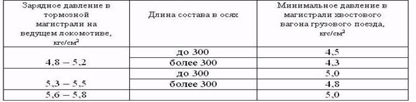
When the charging pressure in the TM of the leading locomotive of the freight train is 4.8-5.2 atm or 5.3-5.5 atm, the pressure in the TM of the tail car with a length of up to 300 axles must be at least 4.5 atm or 5.0 atm , and with a train length of more than 300 axles - not less than 4.3 atm or 4.8 atm, with a charging pressure on the locomotive of 5.6-5.8 atm - not less than 5.0 atm.
The driver, having received the certificate, is obliged to make sure that the data on the train brakes indicated in it comply with the standards.